
Abstract
Cold rotary forging is an advanced but very complicated metal forming technology with multifactor coupling interactive effects. The purpose of this paper is to utilise the finite element (FE) method to reveal the effect of the process parameters on the wear that occurs over the surfaces of the dies and workpiece in cold rotary forging. For this purpose, a three-dimensional (3D) elastic–plastic dynamic explicit FE model of cold rotary forging of 20CrMnTi alloy was developed using the FE software ABAQUS/Explicit, and its validity was verified experimentally. According to the valid 3D FE model, a parametric study was conducted, examining the effect of the major process parameters on the wear response and optimising the process parameters. The results of this research thoroughly reveal the complicated wear mechanisms over the dies and workpieces and provide an important guide for optimising the process parameters in cold rotary forging.
Introduction
Investigating wear problems has a great significance in the improvement of contact performance between the contact interactions.1 – 16 However, wear is still a mystery in the metal forming process because the die/workpiece interface is under a complex dynamic state. Especially in a complex continuous local plastic forming process, the wear behaviour is much more complicated than that in overall metal forming. Therefore, it is necessary to understand the wear behaviour in the continuous local plastic forming process.
Cold rotary forging is just a complicated continuous local plastic forming process. Up to now, many studies have been conducted on cold rotary forging.17 – 28 However, these studies were mainly concentrated on the deformation mechanisms of the workpiece, and the investigation on the wear problems between the dies and workpiece is still limited.29 Cold rotary forging is a complicated metal forming technology with multifactor coupling interactive effects, and the effect of the process parameters on the wear mechanisms in cold rotary forging requires more understanding.
Consequently, this paper aims to utilise the finite element (FE) method to reveal the effect of the process parameters on the wear behaviour in a complex continuous local forming technology of cold rotary forging. For this purpose, a reasonable three-dimensional (3D) elastic–plastic dynamic explicit FE model of cold rotary forging of 20CrMnTi alloy is developed using the FE software ABAQUS/Explicit. According to the valid 3D FE model, a parametric study is conducted, examining the effect of the major process parameters on the wear response and optimising the process parameters.
Development and validation of 3D FE model of cold rotary forging
Cold rotary forging has been attracting more and more applications in many industrial fields, such as automobile, machine tool, electrical equipment, cutting tool and hardware, due to its advantages, including a lower level of noise and vibration, uniform quality, smooth surface, close tolerance and considerable savings in energy and materials cost. A typical cold rotary forging process is illustrated in Fig. 1. During the process, the upper die with an inclination angle γ oscillates continuously around the vertical machine axis at a constant rotational speed n. Simultaneously, the lower die pushes the workpiece vertically at a constant feedrate v so as to cause the axial compression. After the workpiece is pressed repeatedly, the plastic deformation is completed.
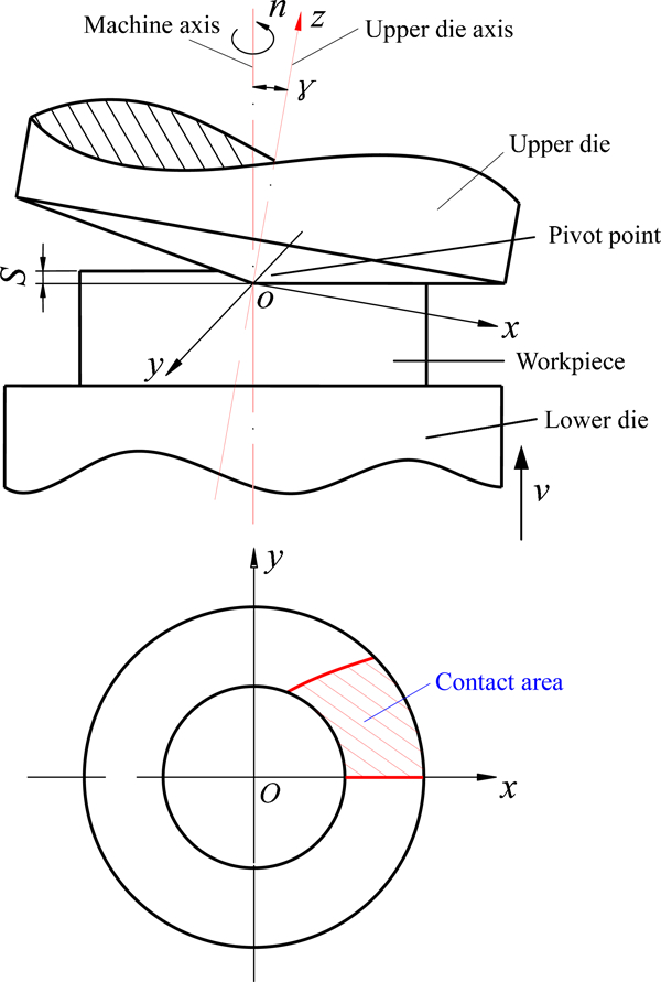
Schematic diagram of cold rotary forging
From the above description, it can be seen that the contact and wear behaviour in cold rotary forging are very complicated, and, thus the FE method is adopted to reveal the complicated wear behaviour in cold rotary forging in this study. Using the FE code ABAQUS, a 3D elastic–plastic dynamic explicit FE model of cold rotary forging is developed as shown in Fig. 2.
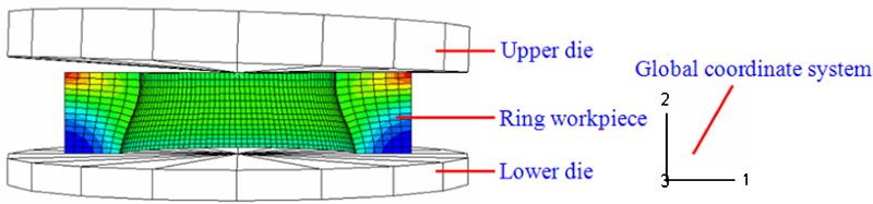
Three-dimensional FE model of cold rotary forging
Development of 3D FE model of cold rotary forging
Workpiece material
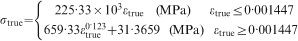
The workpiece material for the study was 20CrMnTi alloy, and the tensile test was carried out to obtain its mechanical properties. The constitutive equation of 20CrMnTi alloy is obtained by fitting the experimental data into the simplified Ramberg–Osgood model in MATLAB and is expressed as equation (1)29
Ring compression test
The classical Coulomb model was adopted to describe the friction conditions in cold rotary forging. The ring compression test was conducted to determine the friction coefficient, μ, between the dies and workpiece. In this test, standard ring samples of OD/ID/H = 6∶3∶2 (30∶15∶10 mm) are adopted and MoS2 used as a lubricant. Figure 3 provides the friction calibration curves of 20CrMnTi alloy under the lubricated condition. From Fig. 3, it can be derived that the friction coefficient between the dies and workpiece is 0·075 under the lubricated condition.
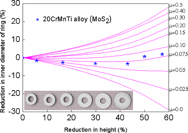
Friction calibration curves of 20CrMnTi alloy under lubricated condition
Modelling technologies in cold rotary forging
The following are the modelling technologies used in cold rotary forging:29
the elastic plastic formulation is adopted to improve the computational accuracy, and the dynamic explicit FE procedure is adopted to avoid the huge computational time of the static implicit procedure during the simulation process
in the production of the rotary forged parts, the outer surface of the ring workpiece is usually constrained so that the metal can only flow towards the inner surface, so all degrees of freedom of the outer surface of the ring workpiece are constrained except that in the axial direction in the modelling process
the C3D8R element is used to discretise the ring workpiece; meanwhile, the adaptive remeshing technology is utilised to reduce the element distortion
two contact pairs are established in cold rotary forging: upper die–workpiece and lower die–workpiece. The two interactions are defined using the ‘master–slave’ algorithm in ABAQUS/Explicit.
Evaluation of developed 3D FE model
The developed 3D FE model of cold rotary forging has been verified experimentally.29 The process parameters adopted in the simulation and experiment are summarised in Table 1. The experiment was carried out on a T 200 cold rotary forging press. In the experiment, 20CrMnTi alloy under isothermal spheroidisation was adopted as the workpiece material, and MoS2 was used as a lubricant. The comparison between the simulation and experimental results is shown in Fig. 4. From Fig. 4, it can be found that the simulation results are in good agreement with the experimental results, and the maximum relative error is 1·73%. Thus, the established 3D FE model of cold rotary forging is proven to be reliable.
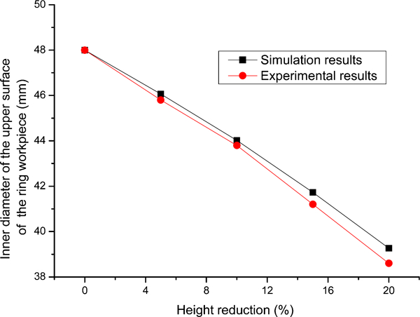
Comparison between simulation and experimental results in cold rotary forging
Process parameters adopted in simulation and experiment
Results and discussion
According to Archard’s wear law,30 the wear rate W is commonly expressed in the following form
In this study, the responses of the contact pressure and contact slip distance in cold rotary forging are first obtained. Then, the wear response that occurs over the surfaces of the dies and workpiece is achieved based on equation (2). Finally, a parametric study is conducted, examining the effect of the major process parameters on the wear response and optimising the process parameters.
Contact pressure distribution
Figure 5 shows the contact pressure distribution between the upper or lower die and workpiece through the FE simulation.29 It can be found from Fig. 5 that the contact pressure only occurs in the contact area. That is to say, when the nodes in the workpiece are located in the contact area, the contact pressure occurs. When these nodes are thoroughly out of the contact area, no contact pressure occurs, and the contact pressure equals zero.
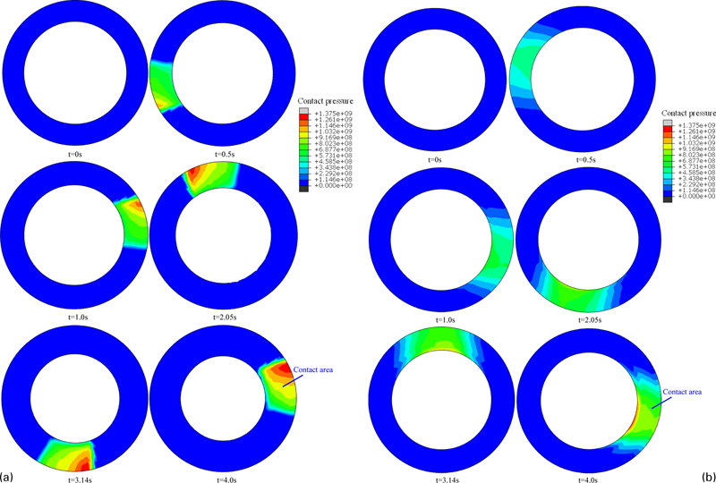
Contact pressure response between dies and workpiece
Contact slip distance distribution
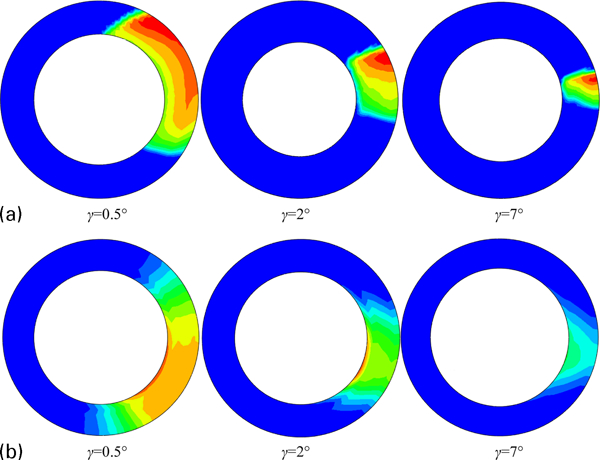
Figure 6 provides the contact slip distance distribution between the upper or lower die and the workpiece through the FE simulation.29 It can be seen from Fig. 6 that the contact slip distance distribution is uniform in the tangential direction while it is very non-uniform in the radial direction, i.e. the contact slip distance between the upper or lower die and workpiece gradually increases or decreases from the inner to outer surface of the ring workpiece.
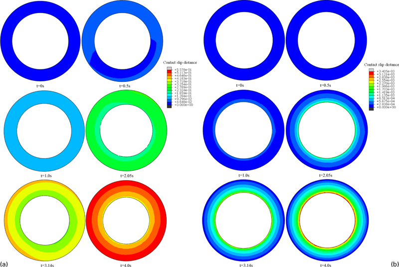
Contact slip distance response between dies and workpiece
Wear distribution
The detailed procedures for calculating the wear response in the FE simulation is illustrated in Fig. 7. According to the calculation method described above, the wear response between the dies and workpiece in cold rotary forging can be obtained through the FE simulation as shown in Fig. 8. It can be found from Fig. 8 that the wear distribution over the surfaces of the deformed ring workpiece is non-uniform in the radial direction. In the four different radial paths, the wear distribution is approximately identical, which indicates that the wear distribution in the tangential direction is very uniform.
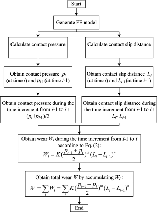
Flow chart of calculation of wear in FE simulation
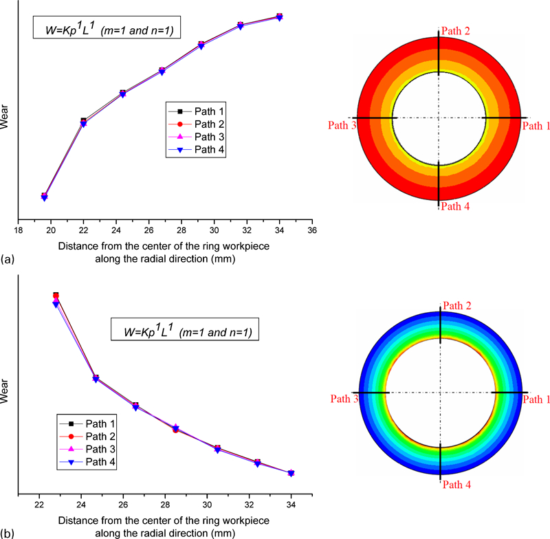
Wear distribution on a upper and b lower surface of ring workpiece along radial direction
Effect of process parameters on wear
Using the reliable 3D FE model, the effect of the process parameters on the wear response in cold rotary forging is examined. The inclination angle γ of the upper die, rotational speed n of the upper die and feedrate v of the lower die are the three critical process parameters in the cold rotary forging process.24 – 28 Moreover, the role of feedrate v of the lower die and rotational speed n of the upper die can be attributed to the role of feed amount per revolution S (S = 60ν/n). Therefore, this study focuses on examining the effect of γ and S on the wear response in cold rotary forging. According to equation (2), the contact pressure and contact slip distance govern the variation in wear together. Therefore, the effect of γ and S on the contact pressure and contact slip distance has to be investigated before examining their effect on the wear response in cold rotary forging.
Effect of inclination angle γ on wear
In order to investigate the effect of γ on the wear response, values of γ = (0·5, 1, 2, 3, 4, 5, 6, 7°) and S = 0·2 mm rev−1were used while keeping the other parameters listed in Table 1 unchanged. Figure 9 shows the effect of γ on the contact pressure between the dies and workpiece in cold rotary forging. It can be seen from Fig. 9 that with increasing γ, the contact pressure between the upper die and the workpiece gradually increases (Fig. 9a ) while the contact pressure between the lower die and the workpiece gradually decreases (Fig. 9b ). The reason for this can be explained qualitatively from the view of the contact area (Fig. 10) and axial forging force (Fig. 11). It is evident that the increase in the contact area or the decrease in the axial forging force will result in the decrease in the contact pressure and vice versa. It can be seen from Figs. 10 and 11 that both the contact area and the axial forging force decrease as γ increases. Therefore, for the effect of γ on the contact pressure between the upper die and the workpiece, the contact area has a more notable role than the axial forging force under this condition. For the effect of γ on the contact pressure between the lower die and the workpiece, the role of the axial forging force outweighs that of the contact area under this condition.
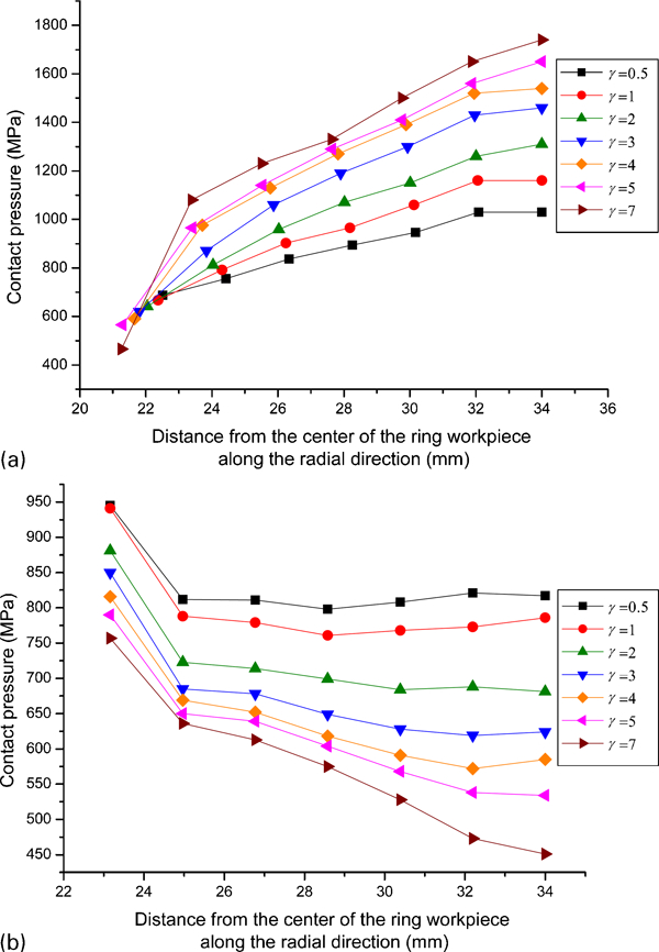
Effect of γ on contact pressure between dies and workpiece
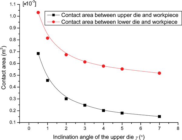
Effect of γ on contact area between dies and workpiece
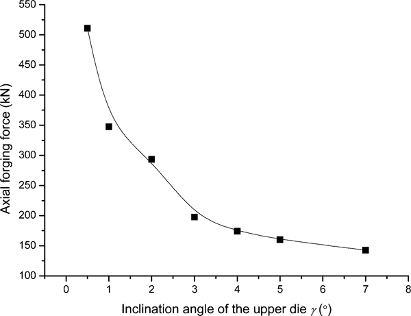
Effect of γ on axial forging force
Figure 12 shows the effect of γ on the contact slip distance between the dies and the workpiece in cold rotary forging. From Fig. 12, it can be found that the contact slip distance gradually decreases with increasing γ. This is because under the fixed value of S, the contact area between the dies and the workpiece gradually decreases with the increase of γ, as shown in Fig. 13. That is to say, fewer nodes in the workpiece participate in the slip at any moment as γ increases. Under this circumstance, fewer nodes repeatedly enter the contact area during the entire process, thus resulting in the gradual decrease in the total contact slip distance with increasing γ.
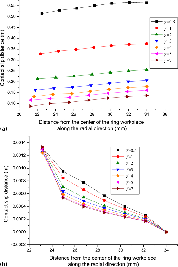
Effect of γ on contact slip distance between dies and workpiece
Effect of γ on contact area between dies and workpiece
After obtaining the effect of γ on the contact pressure and contact slip distance, the effect of γ on the wear can be achieved accordingly based on the calculation method described above. Figure 14 provides the effect of γ on the wear between the upper die and the workpiece in cold rotary forging. It can be found from Fig. 14a that the wear between the upper die and the workpiece gradually decreases with increasing γ. In order to investigate the effect of γ on the wear in more detail, three special nodes in the workpiece along the radial direction were considered as tracking points to monitor the wear variation with γ, as shown in Fig. 14b . It can be seen from Fig. 14b that for the three different nodes, their wear variation laws with γ are the same, i.e. the wear exhibits a non-linear but monotonic response to changing γ. With increasing γ, the wear decreases significantly when γ is smaller than 3°, but it decreases slowly as γ exceeds 3°. This is caused by the following two aspects. On one hand, the contact pressure between the upper die and the workpiece gradually increases with increasing γ. On the other hand, the contact slip distance gradually decreases as γ increases. The two aspects govern the variation in wear together, and it is found that when γ is smaller than 3°, the role of the contact slip distance is more remarkable than that of the contact pressure under this condition. However, as γ exceeds 3°, the role of the contact slip distance is approximately identical with that of the contact pressure under this condition.
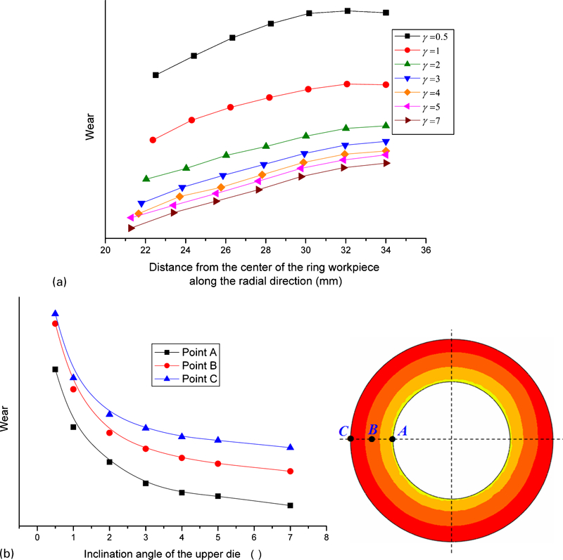
Effect of γ on wear between upper die and workpiece
The effect of γ on the wear between the lower die and the workpiece in cold rotary forging is shown in Fig. 15. From Fig. 15a , it can be found that the wear between the lower die and the workpiece gradually decreases with increasing γ. Figure 15b provides the effect of γ on the wear between the lower die and the workpiece for the three special nodes. It can be seen from Fig. 15b that for the three different nodes, their wear variation laws with γ are approximately identical, i.e. γ has a strong inverse effect on the wear between the lower die and the workpiece. As γ increases, the wear decreases quickly when γ is smaller than 3°, but it decreases slowly when γ is larger than 3°. This is because both the contact pressure (Fig. 9b ) and contact slip distance (Fig. 12b ) decrease gradually with the increase of γ. The combined roles of variations in the contact pressure and contact slip distance lead to the above variation in the wear.
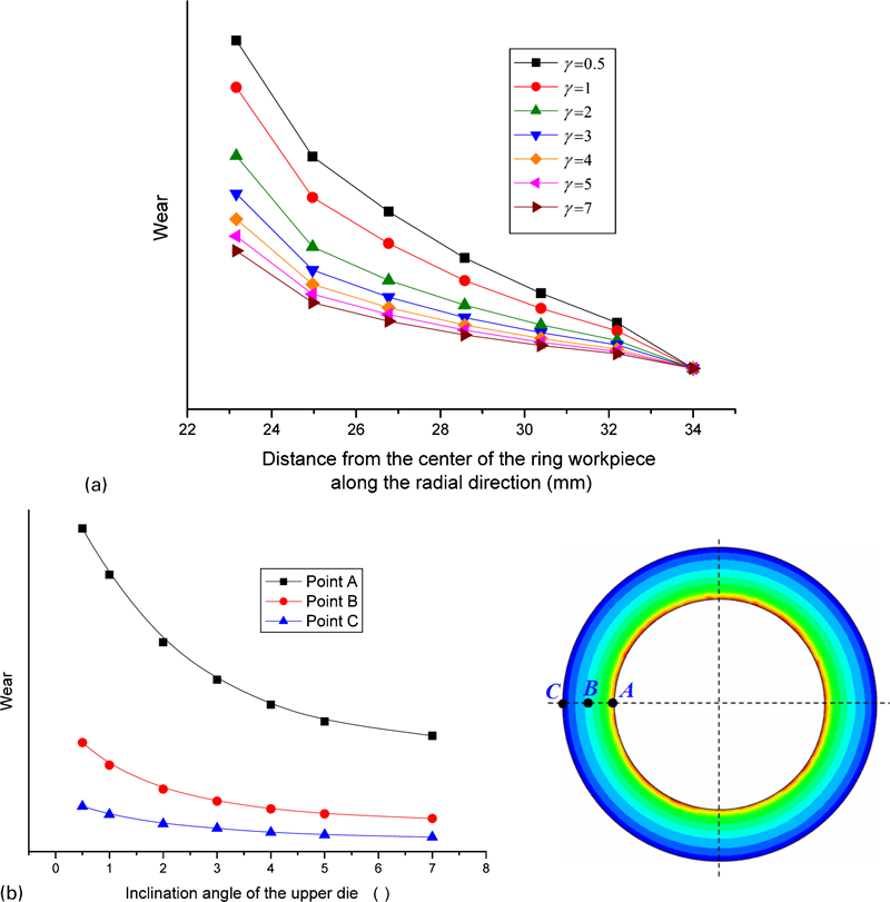
Effect of γ on wear between lower die and workpiece
From the above analysis, it can be concluded that the effect laws of γ on the wear between the upper die and the workpiece is the same as that between the lower die and the workpiece. However, the effect mechanisms are obviously different. Generally, the inclination angle of the upper die γ is set to be below 3° in cold rotary forging.32 From Figure 14 Figs. 14 and 15, it can be seen that the wear between the dies and workpiece decreases quickly when γ is below 3°, but it decreases slowly when γ exceeds 3°. Therefore, the optimal inclination angle of the upper die γ is ∼3° in view of the wear during the cold rotary forging process.
Effect of feedrate S on wear
In order to investigate the effect of S on the wear response, values of S = {0·06, 0·12, 0·2, 0·4, 0·6, 1} (mm rev−1) and γ = 2° were selected while keep the other parameters listed in Table 1 unchanged. Figure 16 illustrates the effect of S on the contact pressure between the dies and the workpiece in cold rotary forging. It can be found from Fig. 16 that with increasing S, the contact pressure between the upper die and the workpiece gradually decreases (Fig. 16a ) while the contact pressure between the lower die and the workpiece gradually increases (Fig. 16b ). The reason for this can also be explained qualitatively from the view of the contact area (Fig. 17) and axial forging force (Fig. 18). From Figs. 17 and 18, it can be seen that both the contact area and the axial forging force increase as S increases. Therefore, for the effect of S on the contact pressure between the upper die and the workpiece, the role of the contact area is more remarkable than that of the axial forging force under this condition. For the effect of S on the contact pressure between the lower die and the workpiece, the axial forging force has a more notable role than the contact area under this condition.
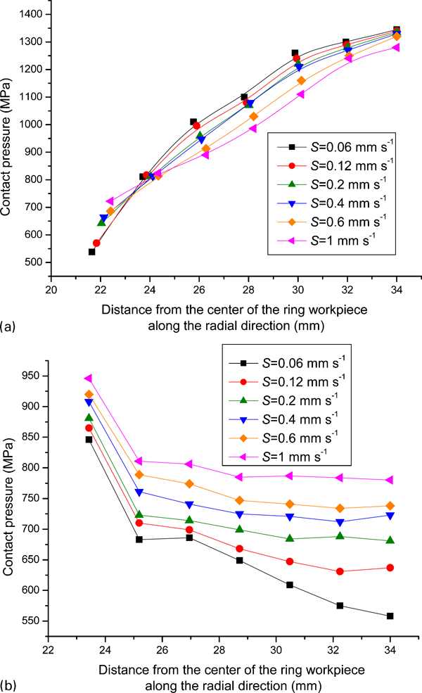
Effect of S on contact pressure between dies and workpiece
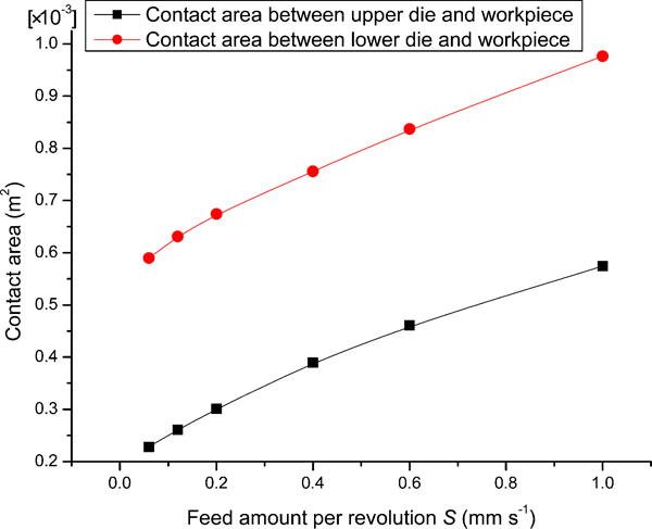
Effect of S on contact area between dies and workpiece
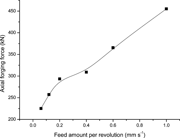
Effect of S on axial forging force
Figure 19 shows the effect of S on the contact slip distance between the dies and the workpiece in cold rotary forging. From Fig. 19, it can be seen that the contact slip distance gradually decreases as S increases. This is because under the fixed γ, the larger the S, the smaller the revolution number of the upper die during the entire process and vice versa. It is evident that the smaller revolution number of the upper die corresponds to the lowered contact time between the dies and the workpiece, thus leading to the gradual decrease in the total contact slip distance with increasing S.
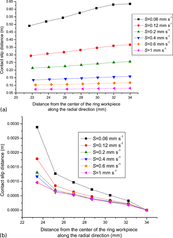
Effect of S on contact slip distance between dies and workpiece
Figure 20 provides the effect of S on the wear between the upper die and the workpiece in cold rotary forging. It can be found from Fig. 20a that the wear between the upper die and the workpiece gradually decreases with increasing S. Figure 20b shows the wear variation with S for the three special nodes in the workpiece. It can be seen from Fig. 20b , that for the three different nodes, their wear variation trends with S are the same, i.e. the wear exhibits a non-linear but monotonic response to changing S. With increasing S, the wear decreases sharply when S is smaller than 0·2 mm rev−1, but it decreases slowly as S exceeds 0·2 mm rev−1. The reason for this is that both the contact pressure (Fig. 16a ) and contact slip distance (Fig. 19a ) between the upper die and the workpiece gradually decrease with increasing S. The combined roles of variations in the contact pressure and contact slip distance lead to the above variation in the wear.
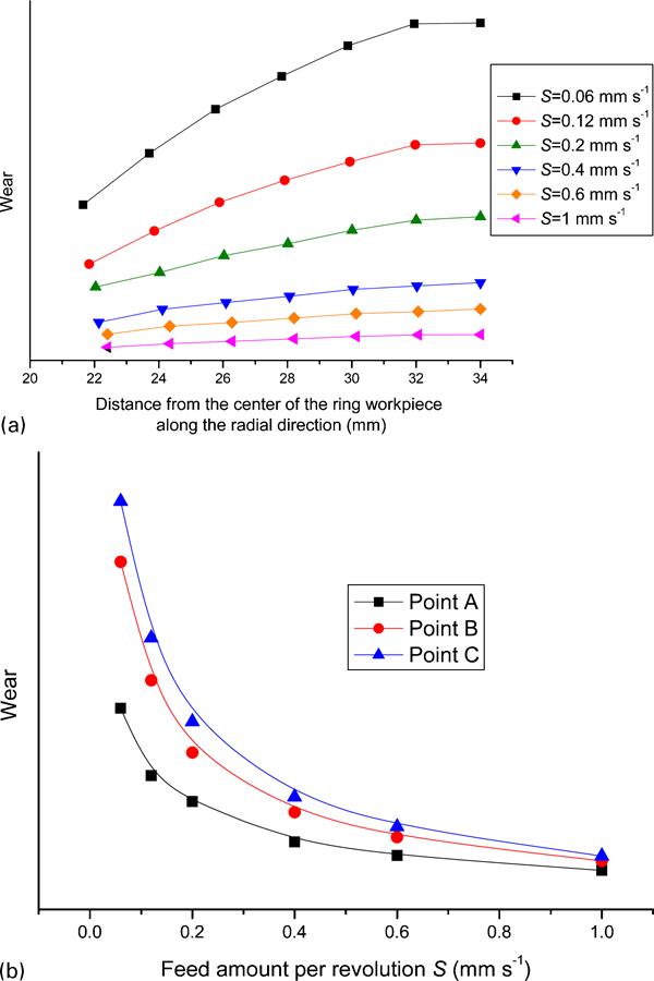
Effect of S on wear between upper die and workpiece
The effect of S on the wear between the lower die and the workpiece in cold rotary forging is shown in Fig. 21. It can be seen from Fig. 21 that for the three different nodes, their wear variation laws with S are approximately identical, i.e. the wear between the lower die and the workpiece exhibits a non-monotonic response to changing S. With increasing S, the wear gradually decreases when S is smaller than 0·2 mm rev−1, but it gradually increases as S exceeds 0·2 mm rev−1. The reason for this can be explained by the following. When S is smaller than 0·2 mm rev−1, the contact pressure between the lower die and the workpiece gradually increases (Fig. 16b ) while the contact slip distance gradually decreases (Fig. 19b ) with increasing S. The two aspects govern the variation in wear together, and it is found that when S is smaller than 0·2 mm rev−1, the role of the contact slip distance is more remarkable than that of the contact pressure under this condition. When S is larger than 0·2 mm rev−1, the contact pressure between the lower die and the workpiece gradually increases (Fig. 16b ) while the contact slip distance gradually decreases (Fig. 19b ) with increasing S. The combined roles of the variations in the contact pressure and contact slip distance lead to the variation in the wear, and it is found that when S is larger than 0·2 mm rev−1, the role of the contact pressure is more remarkable than that of the contact slip distance under this condition.
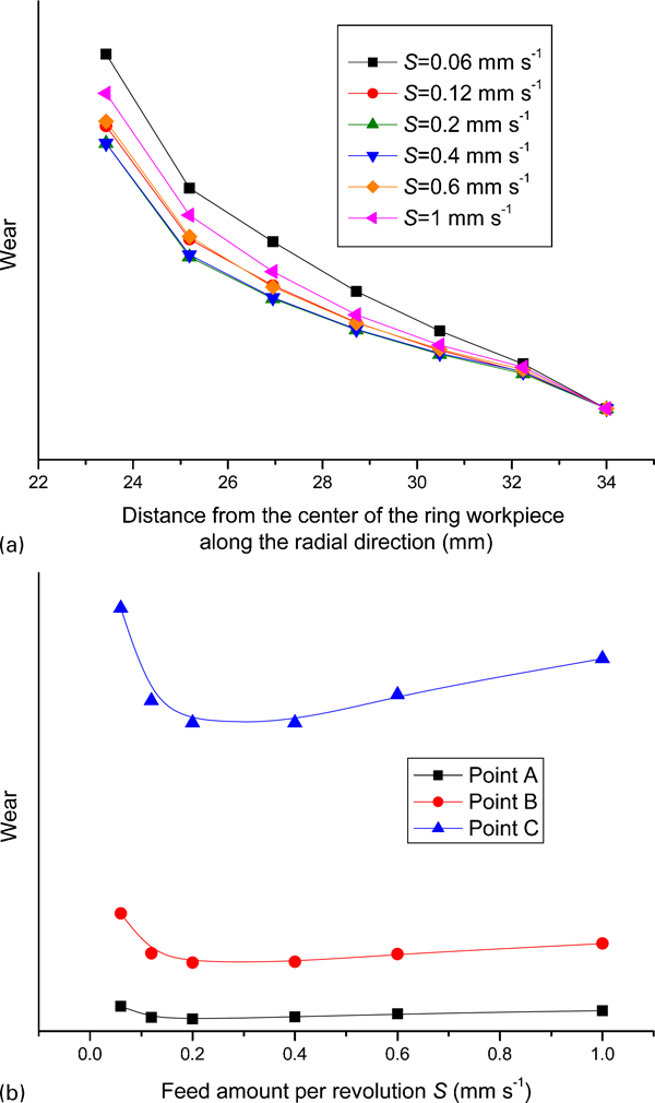
Effect of S on wear between lower die and workpiece
From the above analysis, it can be seen that the wear between the upper die and the workpiece decreases slowly when S is larger than 0·2 mm rev−1 (Fig. 20), and the minimum wear between the lower die and the workpiece occurs when S equals 0·2 mm rev−1 (Fig. 21). Therefore, the optimal feed amount per revolution S is ∼0·2 mm rev−1 in view of the wear during the cold rotary forging process.
Conclusions
This paper utilises the FE method to investigate the wear response in the complicated continuous local plastic forming process of cold rotary forging. The results of this research show the following.
The contact pressure, contact slip distance and wear responses in cold rotary forging are complex, time varying and highly non-linear throughout the forming process.
The process parameters have a significant effect on the wear responses in cold rotary forging. When increasing the inclination angle of the upper die γ, the wear between the dies and workpiece decreases significantly when γ is smaller than 3°, but it decreases slowly as γ exceeds 3°. With increasing the feed amount per revolution S, the wear between the upper die and workpiece decreases sharply when S is smaller than 0·2 mm rev−1, but it decreases slowly as S exceeds 0·2 mm rev−1. The wear between the lower die and workpiece exhibits a non-monotonic response to changing S, i.e. with increasing S, the wear gradually decreases when S is smaller than 0·2 mm rev−1, but it gradually increases as S exceeds 0·2 mm rev−1.
The optimal inclination angle of the upper die γ is ∼3°, and the optimal feed amount per revolution S is ∼0·2 mm rev−1 in view of the wear during the cold rotary forging process.
Footnotes
Acknowledgements
The authors would like to thank the National Basic Research Program of China (grant no. 2011CB706605), Natural Science Foundation of China (grant no. 51105287), State Key Laboratory of Materials Processing and Die & Mould Technology, Huazhong University of Science and Technology (grant no. 2011-P05) and the Fundamental Research Funds for the Central Universities (grant no. 2011-IV-009) for the support given to this research.