
Abstract
A three-dimensional unsteady coupled mathematical model has been applied to analyse the turbulent flow, temperature fields and macroscopic solidification of molten steel in billet continuous casting with electromagnetic stirring (EMS). Induction currents caused by fluid flow and the stirrer end effect have been investigated. The Lorentz force and Joule heat caused by induction currents have also been taken into account. The application of EMS in the secondary cooling zone results in significant changes in molten steel flow and temperature distribution, and the flow patterns on the horizontal cross-section agree well with the results in other references. Joule heat and Lorentz force are mainly located at the surface layer of the billet and decrease rapidly with penetration depth. The degree of superheat is reduced or eliminated rapidly when molten steel is stirred by EMS, hence is beneficial to generate more equiaxed grains. Stirring intensity is highest in the regions near the two ends of the stirrer. The Joule heat produced by induction has limited influence and can be ignored. The industrial trials showed that the EMS can effectively suppress the central shrinkage cavity and the centre C segregation to improve product quality.
Introduction
Electromagnetic stirring (EMS) has gained widespread acceptance in recent years as a method for improving the quality of products.1 – 5 Numerical simulation of EMS has become an important method of study and has great advantages over high cost plant experiments.
Zhang et al. 2 used a two-dimensional numerical model to simulate the solidification structure during continuous casting via the method of combining heat transfer calculation and cellular automaton. The magnetic field generated by the stirrer was simulated by solving the Maxwell equation, and the effects of EMS were investigated with various operating conditions in Refs. 6 and 7. Takatani8 simulated the meniscus EMS with a given constant Lorentz force distribution; however, the fluid flow was not mutual coupled with the electromagnetic field. Natarajan and EI-Kaddah9 developed a new method for solving coupled three-dimensional electromagnetic field and fluid flow without calculating the magnetic field, and that method was used to estimate the velocity distribution in EMS region; however, heat transfer was not considered. Yamazki et al. 10 developed a two-dimensional numerical model to simulate solidification under EMS, and the solidification structure formation was also simulated. Fluid flow, heat transfer and inclusion trajectory for round billet were calculated in Ref. 11 without considering the mushy zone, and the results were partly verified by experiment, in which the laminar flow model was used to estimate the velocity distribution under travelling magnetic field. Magnetic flux density and Lorentz force distribution in billets under EMS were calculated with a simplified stirrer model, and the calculated magnetic field distribution was in good agreement with the experiment only in the non-end part.12 Sivak et al. 13 analysed and substantiated the effectiveness of improving the quality of semifinished sections and rounds cast on casting machines with EMS in the liquid phase of the solidifying steel in the mould and the zone in which final solidification takes place. Govindaraju and Li14 developed an integrated macro-/micromodel to represent the evolution of complex electrodynamic and transport phenomena and solidification microstructures in solidifying metals with EMS, and the result agreed well with the other models.
Most of this work mentioned above only considered the magnetic field generated by the stirrer, and the induced field was ignored. Solidification was not considered in these studies, and the end effect of the stirrer was not discussed. Affected by design parameters and operating conditions, the magnetic field generated by the stirrer is inhomogeneous, so that the calculation of magnetic field should be three-dimensional in order to consider the inhomogeneous field and the end effect of the stirrer. Both the direction and the magnitude of the magnetic field vary with time as the stirrer is fed by ac, so the transport phenomenon of molten steel is in an unsteady state. Solidification of molten steel, while being stirred by Lorentz forces, is a complex process involving turbulent flow and heat transfer and releasing latent heat. In summary, a three-dimensional unsteady model, coupling with fluid flow, heat transfer, solidification and magnetic field, can better describe the transport phenomenon of molten steel in the EMS process.
It is generally accepted that if the stirring intensity is too strong, EMS may lead to central negative carbon segregation, which may result in worse product performance. In order to lessen the side effects of central negative carbon segregation, it is necessary to simultaneously increase the effective length of the EMS and maintain a relatively weaker stirring intensity with limited length of the stirrer. Thus, to extend the effective stirring length of the stirrer, the coil terminations of the stirrer are specifically designed to increase the magnetic flux density near the edge of the stirrer.
Model system
Physical model of stirrer and billet
As shown in Fig. 1a , the stirrer is located 4 m below the meniscus. A physical model of the billet using an electromagnetic stirrer with dimensions 200×200×5000 mm has been used to simulate the velocity and temperature distribution of molten steel. A mould length of 0·7 m and a nozzle diameter of 40 mm have been assumed. The origin of coordinates is set to the centre of the stirrer, and the plane X–Y is set to the middle horizontal cross-section of the stirrer. Figure 1b shows the structure of the stirrer and billet, and Fig. 1c shows a stator (a core and a set of windings) of the stirrer that consists of four stators of linear induction motor with dimensions 250×250×500 mm. Currents in the termination of the coil are considered to accurately calculate the magnetic field and the end effect.
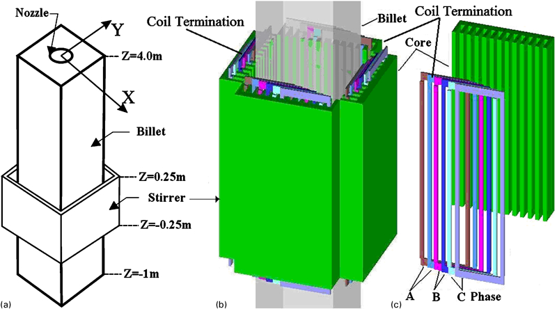
a position of stirrer; b stirrer and billet; c core and winding
Mathematical model
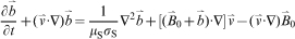
The calculation of the external rotary magnetic field can be treated separately from the fluid flow in the low Reynolds number approximation; hence, numerical simulations consist of three steps. First, fluid flow and heat transfer of molten steel without EMS are calculated. Second, the magnetic field generated by the stirrer is calculated by solving the Maxwell equations in harmonic state based on the finite element method. Finally, repeating the first step with EMS effects is considered. In each iteration of the third step, the induced field is calculated to obtain the total magnetic field, and then the induction current could be used to determine the distribution of Lorentz force and Joule heat power, so the Lorentz force and Joule heat could be considered to simulate the EMS effects.
Governing equations for external rotary magnetic and induced magnetic
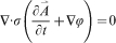
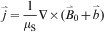
Assuming the displacement current is zero for the low frequency condition, the magnetic vector potential and the electric scalar potential have been calculated to obtain the external rotary magnetic field caused by the stirrer. The governing equations derived by Maxwell’s equation and Ohm’s law are expressed as below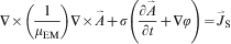


Governing equations for fluid flow and heat transfer
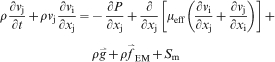
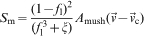
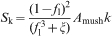
Turbulent flow, temperature fields and macroscopic solidification of molten steel in continuous casting with EMS have been simulated by a three-dimensional unsteady mathematical model. The continuity equation and Reynolds averaged Navier–Stokes equation have been used to calculate fluid flow. The enthalpy–porosity relation has been employed to estimate the velocity within a mushy zone. Standard k–ϵ equation has been adopted to consider the turbulence effects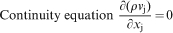


Turbulent kinetic energy equation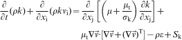
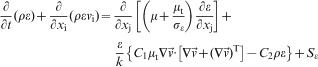

Energy equation
Calculation conditions
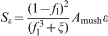
The three-phase coil arrangement9 fed by current with amplitude to 1000 A at 10 Hz per phase is shown in Fig. 2. The coil is made up of four pairs of poles with a distance of 25 mm to the billet, and the polar pitch is 60 mm. The middle horizontal cross-section of the stirrer is located at plane Z = 0 m. Pure iron (relative permeability is 1000) is used for the stirrer core, and the permeability of other materials is equal to vacuum. The conductivities of core, molten steel and cooper winding are 0·01, 7·14×105 and 5·8×107 S m−1 respectively. Ten points along the X axis from the origin was selected to monitor the velocity and temperature trends with stirring time: P0(0,0,0), P1(0·01,0,0),…, P9(0·09,0,0).
Winding arrangement
In order to accurately estimate the dimensions and location of the liquid core within the stirring region, fluid flow and heat transfer have been calculated from the nozzle inlet of the mould to the region below the stirrer, where the stirring is weak. The electromagnetic field is calculated and updated iteratively at each time step.
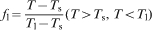
The liquidus temperature is 1515°C, and the solidus temperature is 1483°C. The viscosity of molten steel is determined by its temperature via equation (19) from Ref. 15. A casting temperature of 1540°C and a casting speed of 1·2 m min−1 are assumed. The values of the average heat transfer coefficients chosen are 1500 and 750 W m−1 °C−1 respectively for the mould and water spray cooling regions. The boundary wall is assumed to be free slip, and standard wall function is used to treat the turbulent flow near the wall


The SIMPLE algorithm is applied to solve the momentum and continuity equations. The time step is 0·001 s (1% of frequency for power supply). The convergence criterion for the velocity field was set to <10−5 and energy 10−7.
Results and discussion
Magnetic field and Lorentz force
The vector map of magnetic flux density of the external rotary field and the contour map of the induced field due to fluid motion in a cycle are shown in Figs. 3 and 4. Figure 3 is for plane Z = 0 m, and Fig. 4 is for plane X = 0 m. As shown in Fig. 3, a nearly central symmetrical magnetic field is formed in the horizontal cross-section of the billet. The magnetic flux density of the external rotary field is stronger near the four corners of the billet and weaker in the region of the liquid core, and both magnitude and direction change periodically with time. The distribution of the induced field is similar to the external magnetic field. The same distribution of magnetic flux density is generated near each stator in the billet as they use the same coil arrangement, as shown in Fig. 2. Four segments of the travelling magnetic field are generated by four stators, so the moving direction of the magnetic flux caused by the stirrer rotates anticlockwise when the current is fed in the way shown in Fig. 2. The induced field has little influence on fluid flow as the maximum magnitude of induced field is still <0·01 T and is also <0·001 T in the region of liquid core at plane Z = 0 m.
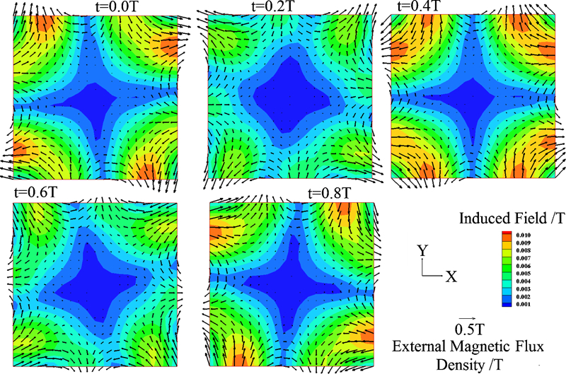
Vector map of magnetic flux density of external field and contour map of induced field in cycle T (Z = 0 m, X–Y plane)
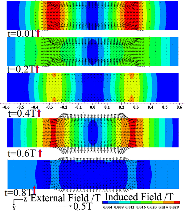
Vector map of flux density of external magnetic and contour map of induced field in cycle T (X = 0 m, Y–Z plane)
Figure 4 indicates that the external field is strongest near the two ends of the stirrer and weakest in the region of the liquid core. Such a distribution is similar to the magnetic flux density distribution of a permanent magnet. Both magnitude and direction of the external field at plane X = 0 m change periodically with a period equal to the frequency of the power supply. The current density near the two ends of the stirrer is stronger for the additional current density in the termination of the coil, so the external field is strongest near the ends of the stirrer. A stronger magnetic field also exists in the zones above the stirrer (Z>0·25 m) and below the stirrer (Z<−0·25 m), which will affect the fluid flow and heat transfer. As a result, the effect of the stirrer on molten steel is not merely limited in the inner zone of the stirrer. A stronger induction current is generated due to the larger external field near the end of the stirrer, which will result in a stronger induced field there. The maximum value of induced magnetic flux density is 0·031 T so that the induced field should not be ignored.
In Figs. 3 and 4, both magnitude and direction of each component of the external field change periodically with time, and the induced field is stronger near the two ends of the stirrer. At any time, the external field decays rapidly with penetration depth and is < 0·1 T in the region of liquid core because of the skin effect. The external field in the liquid core plays a key role in stirring the molten steel. The stronger external field mainly is located in the solidified zone where the magnitude of magnetic flux density is stronger than 0·1 T but has almost no effect on stirring the molten steel.
To verify the numerical results of the electromagnetic field, a T201 Gauss meter has been employed to measure the magnetic flux density on the X–Z plane offline (no billet in stirrer), and three segments Z = −0·2 m, Z = 0·0 m and Z = 0·2 m on the X–Z plane have been selected to verify the ‘edge effect’ caused by current in coil termination. A phase current of 100 A has been assigned to prevent overheat of stirrer by Joule heat when offline. Figure 5a shows the experimental results and Fig. 5b the calculated results. If the experimental current is 1000 A, the measurement results should ideally be 10 times the current experiment value by Biot–Savart law. Both experimental and simulated results indicate that the magnetic flux density is larger near the two edges of the stirrer. The simulation results are much less than the experiment results if the experiment results are multiplied by 10 for the skin effect and complex eddy current distribution in billet. To sum up, the trend of magnetic flux density distribution by simulation agrees well with the experiment.
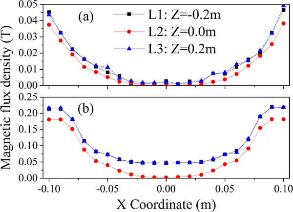
Magnetic flux density on X–Z plane at different heights
Figure 6 shows the distribution of Lorentz force that drives the fluid flow rotating horizontally at the horizontal cross-section (plane Z = 0 m) in a cycle. The Lorentz force decays to the centre of the billet, and the magnitude and direction also change periodically with time. The field of the Lorentz force rotates in the same direction of the external field and also has a central symmetrical distribution. The maximum value of Lorentz force in the liquid core is ∼500 N m−3, which is much less than that in the solidified shell. The magnetic flux density in liquid core is weak, and the relative velocity of molten steel to the external magnetic field is less in liquid core than that in solidified shell; thus, the Lorentz force decays rapidly with penetration depth.
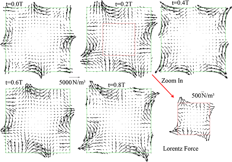
Distribution of Lorentz force at plane Z = 0 m in cycle
The trends of the X component, Y component, horizontal component of Lorentz force and horizontal velocity magnitude of point K (0·04, 0, 0) at X–Y plane Z = 0 m over stirring time are shown in Fig. 7. This figure indicates that these variables vary over stirrer time with a period of 20 Hz (double that of frequency of power supply). For a time harmonic magnetic field, each component of magnetic flux density and induction current is a time harmonic variable; therefore, the Lorentz force is equal to an averaged value added by the time harmonic variable with doubled frequency. Although the magnitude and direction of the X component Lorentz force change with time, the direction of the horizontal component never changes, and the Lorentz force drives the molten steel in a constant direction. The horizontal velocity of point K fluctuates in such a tiny range (< 0·5%) that the fluctuation can be ignored.
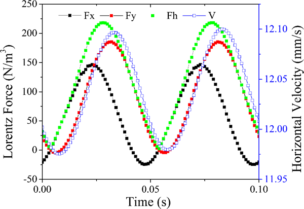
Trend of Lorentz force and velocity of point K
Fluid flow and temperature distribution
In order to investigate the velocity of molten steel after using EMS, Fig. 8 shows a vector map of velocity and contour map of liquid fraction at a horizontal cross-section. Figure 8a is for the case of X–Y plane Z = 0·0 m without EMS, and Fig. 8b–d is for X–Y plane Z = 0·2 m, X–Y plane Z = 0 m and X–Y plane Z = −0·2 m with EMS respectively. Figure 8 indicates that the horizontal component of velocity in molten steel is 0 before EMS is used. The molten steel rotates anticlockwise in the horizontal cross-section, the same direction that the external field rotates in when EMS is turned on. The horizontal velocity in the middle of the stirrer is less than that near the region of the two ends, and the horizontal velocity near the lower end part is less than that of the upper part. The horizontal velocity locates mainly in zones where the liquid fraction is >0·1 and |X|<0·06 m and |Y|<0·06 m, reaches the maximum value where X = ±0·04 m or Y = ±0·04 m and tends to 0 in the centreline of the billet or near the solidification front. The region where the liquid fraction is >0·9 tends to shrink and eventually disappears in the direction of the casting velocity after EMS is used, which indicates that the temperature of liquid core decreases when EMS is turned on. The magnetic flux density is stronger near the two ends of the stirrer; thus, the Lorentz force is stronger there too, which results in the horizontal velocity less in the plane Z = 0 m than that in the planes Z = 0·2 m and Z = −0·2 m. The flow patterns on the horizontal cross-section agree well with the results in Ref. 9 in the region of the liquid core, but the horizontal velocity at the edge of the stirrer is much larger than that at the centre.
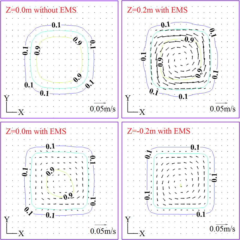
Velocity and liquid fraction distribution at horizontal cross-section
Figure 9 shows the vector map of velocity and the contour map of liquid fraction in a vertical cross-section, Fig. 9a is for Y–Z plane X = 0·04 m without EMS and Fig. 9b and c is for Y–Z plane X = 0·04 m and Y–Z plane X = −0·04 m with EMS respectively. Horizontal velocity exists only when EMS is turned on, and the horizontal velocity of molten steel at Y–Z plane X = 0·04 m and Y–Z plane X = −0·04 m is in the opposite direction, which indicates that the molten steel is stirred. The molten steel in the region above or below the stirrer (|Z|>0·25 m) is still stirred as a magnetic field exists in those regions. The EMS has a significant effect on the liquid fraction as convection in the horizontal direction is enhanced by EMS, which results in speeding up the heat dissipation, decreasing the molten steel temperature and homogenising the temperature field.
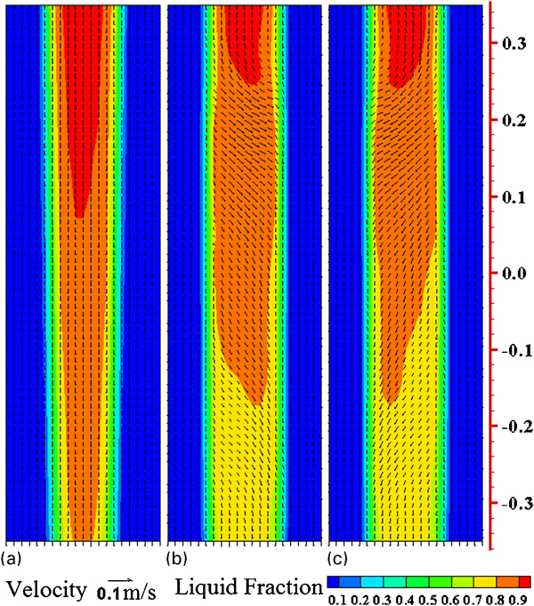
a without EMS (X=0·04 m); b with EMS (X=0·04 m); c with EMS (X=−0·04 m)
The contour map of liquid fraction in Fig. 9 indicates that the temperature decreases in the direction of casting speed within the EMS region. The fluidity of molten steel is poor in the lower part of the EMS region; thus, the average horizontal velocity magnitude is larger on the Y–Z plane Z = 0·2 than that on the Y–Z plane Z = −0·2 m. Although the Lorentz force is larger in the mushy zone than that in the centre zone, the horizontal velocity tends to 0 due to pressure loss near the region of the solidification front.
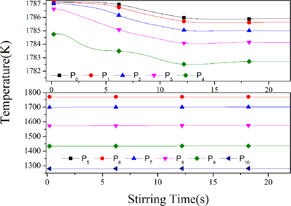
To investigate the effect of stirring on temperature distribution, 12 segments that are of different height on the X–Z plane Y = 0 m have been selected to calculate temperature changes on those segments after using EMS. Figure 10 shows the temperature variation after EMS at different heights in a vertical cross-section (X–Z plane, Y = 0 m). The temperature of molten steel decreases progressively in the liquid core and increases in the solidified shell. On the plane Y = 0 m, in the region above the stirrer, such as segments L1 and L2, the temperature changes very little in the liquid core, and the temperature arises ∼1 K after EMS in the solidified shell. In the region within the stirrer (segments L3, L4,…,L7 in Fig. 10), the temperature decreases more in the liquid core but rises more in the solidified shell in the casting direction. This is due to the enhancement of convection in molten steel by EMS and the longer time span in stirring in the casting direction. In the region below the stirrer (such as segments L8, L9,…, L12), the trends of temperature are similar to the region within the stirrer, and the temperature variation in liquid core tends to uniformity. The molten steel is stirred by EMS with temperature decreasing and homogeneous. The temperature of the solidified shell rises for convection between the liquid core and the solidified shell is enhanced by EMS.
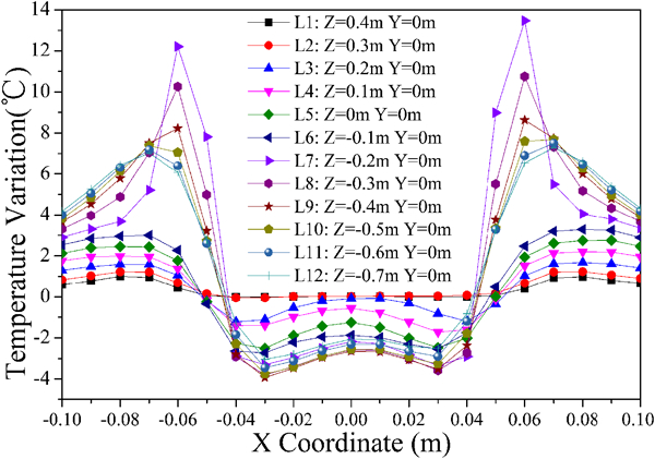
Temperature variation at plane Y = 0 m after EMS
Figure 11 shows the contour map of Joule heat power at plane X = 0 m, and the distribution indicates that Joule heat is mainly situated in the surface layer and the end part of the stirrer where the induction current is stronger. Joule heat has almost no effect on the temperature field.
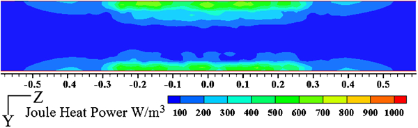
Contour map of Joule heat in plane X = 0 m
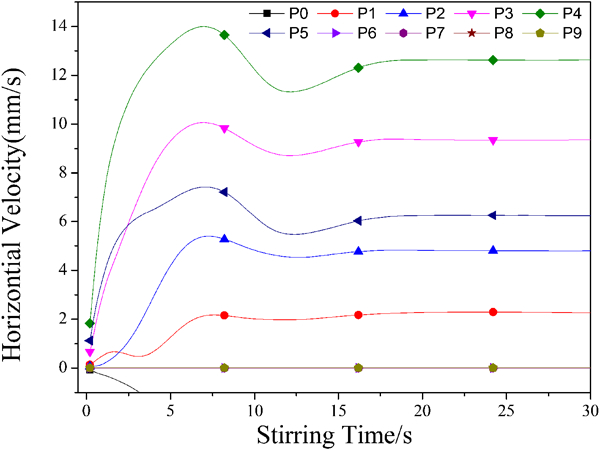
Figures 12 and 13 show the trends for temperature and horizontal velocity of 10 points (P0, P1,…, P9, as shown in Fig. 2) with stirring time. Figure 12 indicates that the temperature in liquid core decreases and eventually tends to constant values over a stirring time at ∼18 s with EMS, but the temperature in the solidified shell increases slightly. This is prompted by the EMS, which enhances convection in the liquid core. In Fig. 13, the horizontal velocity in the liquid core increases over time, reaches maximum values at ∼7·5 s after EMS is turned on and tends to constant values after 18 s. The horizontal velocity in the solidified shell is 0. The horizontal relative velocity of molten steel to magnetic field decreases when the horizontal velocity of molten steel increases from 0, and thus, the Lorentz force decreases. As a result, the horizontal velocity of molten steel will first increase and reach a maximum value and then decline and eventually stabilise.
Trends for horizontal velocity of 10 points with stirring time
Trends for horizontal velocity of 10 points with stirring time
Industrial trial
Central carbon segregation and central shrinkage cavities of the billet were serious before using EMS in the secondary cooling region. Based on the casting conditions mentioned above, an industrial trial was conducted, and central carbon segregation and central shrinkage cavity data on 100 samples of billet without EMS and 50 samples with EMS were performed to investigate the effect of EMS. Figure 14 shows cross-sections of billet samples; it is clearly seen that the central shrinkage cavities are effectively suppressed.
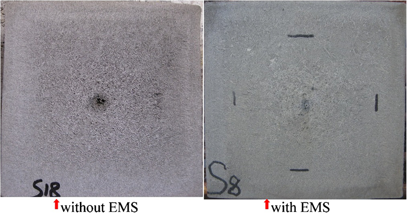
Photomicrographs of billet
To quantitatively evaluate the effects of EMS on billet quality, the grades of central shrinkage cavities were evaluated, and the index of central carbon segregation calculated. The results are shown in Figs. 15 and 16 respectively. In Fig. 15, the grade of central shrinkage cavities does not exceed 2, and the percentage of samples whose grade is not higher than 0·5 is more than 60% after using EMS. In Fig. 16, central carbon segregation has been suppressed using EMS: the average index of central carbon segregation drops from 1·12 to 1·08, and the standard deviation drops from 0·094 to 0·068 after stirring. These phenomena may be due to the enhancement of horizontal stirring flow of molten steel and effective solute mixing by the stirrer.
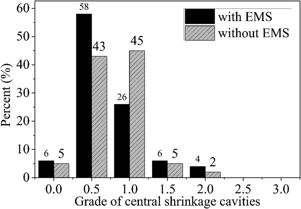
Central shrinkage cavities of billet
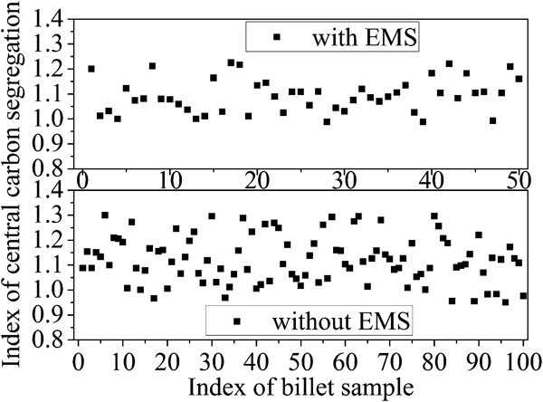
Central carbon segregation of billet
Conclusions
A three-dimensional analysis of the coupled turbulent flow and solidification was performed in the billet continuous casting process with secondary cooling region EMS, in which the induced field and Joule heat were also considered. Conclusions can be summarised as follows.
The stirring intensity is strongest in the region near the two ends of the stirrer, where the magnetic flux density and the induced field are strongest.
The EMS quickly reduces and homogenises the temperature in the liquid core region and increases the temperature of solidified shell and solidification front.
The rotational speed of molten steel will first increase, then decrease and eventually reach a constant value for the balance of the Lorentz force and viscosity. The horizontal velocity of molten steel near the edge of the stirrer is larger than that in middle of the stirrer.
Lorentz force and Joule heat are mainly located in the surface layer of the billet and decay rapidly with penetration depth. Joule heat has almost little effect on heat transfer in the billet. Lorentz force is a periodical force with double the frequency of the power supply.
The industrial trials showed that the EMS can effectively suppress the central shrinkage cavity and the centre C segregation.