
Abstract
A three-dimensional numerical model was used to simulate the gas–char two phase flow and combustion characteristics in the raceway of a COREX melter/gasifier. The flow was depicted using Euler–Lagrangian models, and a kinetic/diffusion limited rate model was used to simulate char oxidation and the gasification reaction. The models were used to predict the main features of the complicated gas–solid flow and combustion. The gas temperature, velocity distribution in the raceway, and gas species distribution were also obtained. The results show that large scale recirculation occurred in the raceway. Furthermore, the effects of oxygen velocity, purity and temperature on the gas temperature distribution in the raceway were studied. The findings provide a reliable theoretical basis for optimisation of operating parameters and further research of the COREX process.
Introduction
COREX is the first commercially operating smelting reduction process using non-coking coal as fuel and comprises a reduction shaft and a melter/gasifier, as shown in Fig. 1.1 Lump ore/pellet along with flux and coke are continuously added via the top of the reduction shaft furnace, and the ore/pellet is reduced to ∼90% metallised iron by the reducing gas mixture from the melter/gasifier consisting mainly of CO and H2 at ∼850°C.1, 2 The metallised iron, also known as direct reduced iron (DRI), along with calcined limestone, dolomite and lump coal, are fed into the melter/gasifier, as shown in Fig. 2, and which is functionally divided into four parts: freeboard, fluidised bed, moving bed and hearth. Pure oxygen blown through the tuyere burns the coal char in the moving bed and generates CO and heat, forming a raceway in front of the tuyere, as shown in Fig. 3.3 An adhesive layer forms due to molten char ashes and a fine layer of char in the bottom of the raceway. The main gas flows in an upward direction. Owing to pure oxygen injection, the temperature near the tuyere is higher than that in a blast furnace, despite the high temperature air injection in the blast furnace. The char combustion in the raceway supplies sufficient reducing gas and heat for the final reduction and melting of DRI, as well as for the formation of slag and generation of reduction gases that will be consumed in the reduction shaft. It is important to understand the gas–char two phase flow and combustion characteristics in the melter/gasifier raceway.
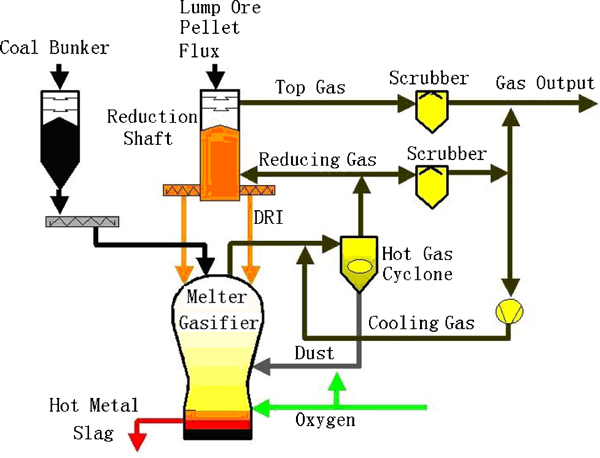
Diagram of COREX process
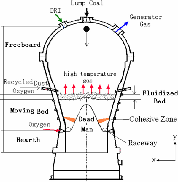
Diagram of melter/gasifier
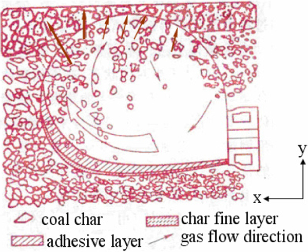
Diagram of gas and char flow in raceway
In recent years, some research works related to COREX have been published. Wu et al. 4 developed a two-dimensional mathematical model to describe iron oxide reduction in the reduction shaft furnace, considering mass, momentum and heat transfers between gas and solid phases in a steady state. Their model was used to calculate and demonstrate the basic characteristics of the reduction shaft furnace, such as velocity, pressure, temperature fields of relevant phases, and species mass fraction distributions. Without considering the effect of gas temperature, Wang et al. 5 studied the gas velocity and pressure distribution in the melter/gasifier using a two-dimensional mathematical model. Their results showed that the bed void caused by particle diameter and their manner of packing significantly influenced the gas flow. A ‘V’ shaped bed provided the optimum gas flow. Berger et al. 6 studied the combustion of recycled dust in the freeboard by Fluent software and obtained the distribution of the gas temperature and species concentration. Lee et al., 7 7,8 Shin et al.,9 Li et al.,10 Wang et al.,11, 12 and Subrata et al. 13 developed a one-dimensional mathematical model for the moving bed considering the conservation of mass and energy. The model was used to study the temperature distribution of gas and solid, gas species concentration distribution, and the effect of moving bed height on heat and mass transfer. Subrata et al. 13 studied the combustion of coal char in the raceway of the moving bed using a two-dimensional mathematical model and obtained the temperature distribution of gas and solid and gas species distribution, considering gas and solid as continuous medium and the gas and solid interaction. A three-dimensional mathematical model was developed by Subrata et al.,14 which was used to analyse the transport phenomena of a moving bed when blocking one or multiple tuyeres for various reasons. At the same time, Subrata et al. 15 developed a dynamic model of the melter/gasifier to study transient behaviour. The effect of various factors on the temperature of hot metal and top gas was obtained, such as on the changes of O2 flowrate, charging rate and DRI to fuel ratio. Zhao16 studied the combustion of coal char in the raceway of a moving bed using a three-dimensional mathematical model, considering the raceway as a porous medium made up of char, and obtained the distribution of gas temperature, velocity and species.
In the above research, char was considered as a continuous or porous medium. However, in most research on coal/coke combustion in a blast furnace raceway, coal/coke is considered as a discrete phase. Shen et al. 17 – 20 and Guo et al. 21 developed three-dimensional mathematical models using Euler–Lagrangian approaches to simulate the flow and combustion of coal under simplified blast furnace conditions. The pattern of gas–solid flow and distribution of gas species were obtained, and the model was validated using experiment results from a combustion test rig.
Most works have focused on transport phenomena in the moving bed of a COREX melter/gasifier, and only a few researchers have focused on the gas–char two phase flow and combustion characteristics in the raceway. In the raceway the combustion of char generates more hot reducing gas. The deoxidisation and melting of DRI, formation of slag, and decomposition of lump coal in the moving bed by the high temperature reducing gases are critical factors for the quality of hot metal. Therefore, the gas–char two phase flow and combustion performance in the COREX raceway have a great effect on the transport phenomena.
The assumption that char in the raceway is a continuous or porous medium is inappropriate because the char runs with gas flow and the volume fraction of char is much less compared with that of gas in the raceway. In the present work, char is regarded as a discrete phase and gas flow is assumed as a continuous medium, as in other research of the blast furnace raceway.17 – 21 A three-dimensional mathematical model using Euler–Lagrangian approaches was developed to simulate the gas–char two phase flow and combustion characteristics in the COREX raceway. The influences of oxygen velocity, purity and temperature on the combustion characteristics in the raceway were investigated.
Mathematical model
In the present work, the raceway was assumed as a cuboid or cylinder for simplification, following a previous study.21, 22 The raceway of the computation domain was 80 cm in depth, 70 cm in height and 70 cm in width, as shown in Fig. 4, as estimated for COREX-3000 by Baosteel. The tuyere was 30 mm in diameter. An arrow represents the gas flow direction.
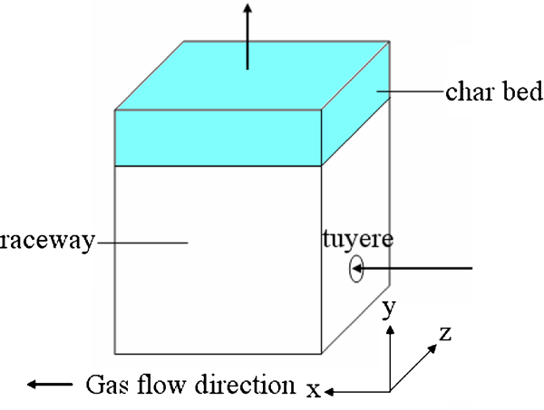
Diagram of raceway computational domain
Gas–solid flow
The flow of gas was described by a set of three-dimensional steady state Reynolds averaged Navier–Stokes equations closed by the κ–ϵ turbulence model. The general flow governing equation can be written as
Variables Φ, Γ eff and S Φ in governing equations for gas phase
The particle phase was modelled using the Langrangian approach. For simplicity, the physical interaction between char particles was not considered. The movements of the particles were calculated according to Newton’s second law of motion
Char combustion reaction model23
The kinetic/diffusion limited rate model was used to simulate the char oxidation and gasification reactions. Surface reaction rate was assumed as determined by either by kinetics or by diffusion rate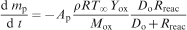
The particle temperature was governed by a heat balance of three fluxes: convective heat transfer, heat released by the surface reaction and radiative heat transfer
Radiation model23
Radiation in the raceway was simulated by the P-1 model from Fluent due to its lower computation expense; the weighted sum of gray gases model was used for computation of the absorption coefficient.
Boundary conditions
The velocity inlet boundary condition for the gas inlet and pressure outlet boundary condition for the outlet of gas were used in the simulation. The top of the raceway was a char bed, regarded as a porous medium, with 0·45 porosity. The bottom and side faces of the raceway were considered as walls because the main gas flow direction was in the y direction. At the tuyere the blowing velocity of oxygen with 99·5% purity at 300 K was 170 m s−1. Finally, the temperature of char particle (∼8 mm in diameter) falling into raceway was ∼1800 K.
Numerical method
The model governing equations were solved numerically using the finite volume method. For the convective term an upwind scheme was used for discretisation. The gas mass and momentum equation were solved using SIMPLE algorithm to deal with coupling of velocity and pressure, under the grid system of 222,000 cells in computation in computation. The model was solved using the framework of Fluent 6·3.
Results and discussion
Base case
The operating parameters used in base case from a melter/gasifier were as follows: oxygen blowing velocity at the tuyere was 170 m s−1 and purity was 99·5%.
Gas flow field and particle trajectories
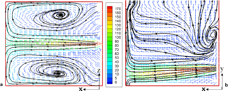
Figure 5 shows the gas phase velocities in the cross-sections of the X–Z plane and X–Y plane before the tuyere. The high speed gas exiting the tuyere formed a central jet. The gas velocity decreased rapidly from 170 to 40 m s−1 along the x direction due to the area enlargement of flow channel and gas flow resistance. Two large scale gas flow recirculation regions were formed: one beside the central jet in the X–Z section, and one above the tuyere in the X–Y section. These regions enabled the char and oxygen to mix rapidly and uniformly, aiding the combustion of char. The particle trajectories viewed from y and z directions, as shown in Fig. 6, were similar to gas flow velocities due to particle moving with gas flow. In the recirculation regions, the residence time of particles was approximately 0·5–1·5 s, which was longer than that of other regions due to the recirculation of particles with gas flow. As a result, the particles in the recirculation regions were able to combust more sufficiently.
Gas velocity vectors coloured by velocity magnitude (m s−1)
Particle trajectories coloured by particle residence time (s)
Distribution of gas temperature and species
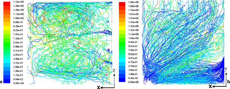
Figure 7 shows the gas temperature and Figs. 8–10 show the distribution of gas species in X–Z and X–Y sections before the tuyere. The temperature of the gas was low in the core of central jet region due to the inlet temperature of oxygen at 300 K, which helped protect the tuyere from burning out. Along with the gas flow in the forward direction, the gas temperature rose rapidly above 2400 K inside the central jet region, where the char combusted violently and the peak temperature was ∼3000 K. In the region beside the central jet, the gas temperature was relatively uniform and ranged from 1800 to 2100 K.
Gas temperature (K) distributions in the cross sections
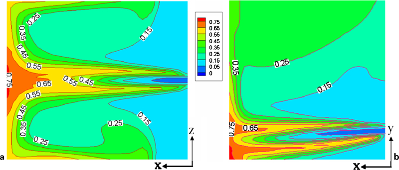
CO mass fraction distributions in the cross sections
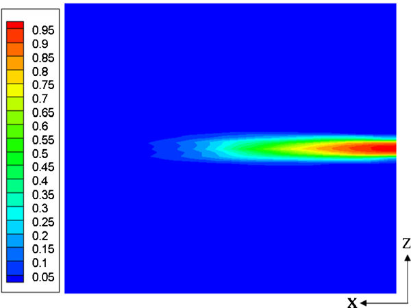
O2 mass fraction distribution in X–Z section
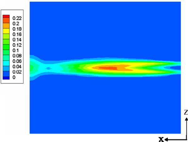
CO2 mass fraction distribution in X–Z section
The O2 mass fraction decreased rapidly inside the raceway after oxygen exited from the tuyere due to char combustion. The CO mass fraction profile was similar to that of gas temperature, because the main combustion production was CO. The CO mass fraction was lower near the tuyere, as a result of the slow reaction rate of char combustion due to the low temperature of oxygen; however, it gradually increased to 0·75 at the end of the central jet region. It decreased sharply beside the central jet region, and a relatively uniform distribution of CO was formed with mass fraction of about 0·15–0·25. The CO2 mass fraction was much less than that of CO inside most of the domain, where the char was abundant for combustion, except in the oxygen rich middle of the central jet region.
Effect of inlet velocities of oxygen
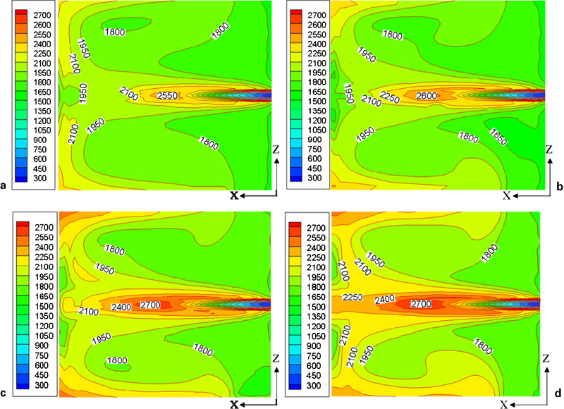
In the COREX process, the tuyeres are often burnt out due to high temperature in the raceway. Here, we investigated the temperature distribution at different inlet oxygen velocities. Figures 11 and 12 show the gas temperature distributions in the X–Z and X–Y sections before the tuyere with different oxygen inlet velocities. Figure 11 shows that the gas temperature profiles were similar with a peak temperature of ∼2700 K, and high temperature of ∼2700 K in the centre domain. However, small differences in the isotherm distribution in the region beside the central jet were evident. The high temperature region surrounded by the isotherm curve of 1950 K enlarged with the increase of oxygen inlet velocity. The char was abundant for combustion reaction in the raceway. With the increase of oxygen inlet velocity, the inlet oxygen mass flowrate increased, consuming more char and releasing more heat. Figure 12 shows that the gas temperature profiles were very similar with the peak temperature of ∼3000 K. The high temperature domains above 2700 K were located at the end of central jet region, far from the tuyere. The shape of flames was also similar; the increase of inlet velocities had little effect on the length of flames and peak temperature domains. In the X–Y sections, the increase of inlet velocities had little effect on gas temperature distribution compared with in the X–Z sections.
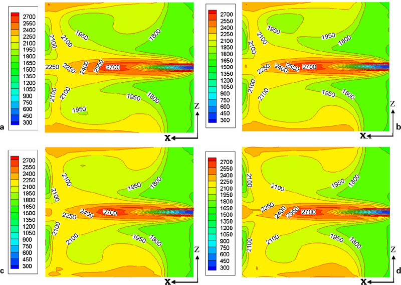
Gas temperature distributions in X–Z section with different inlet velocities of oxygen (K)
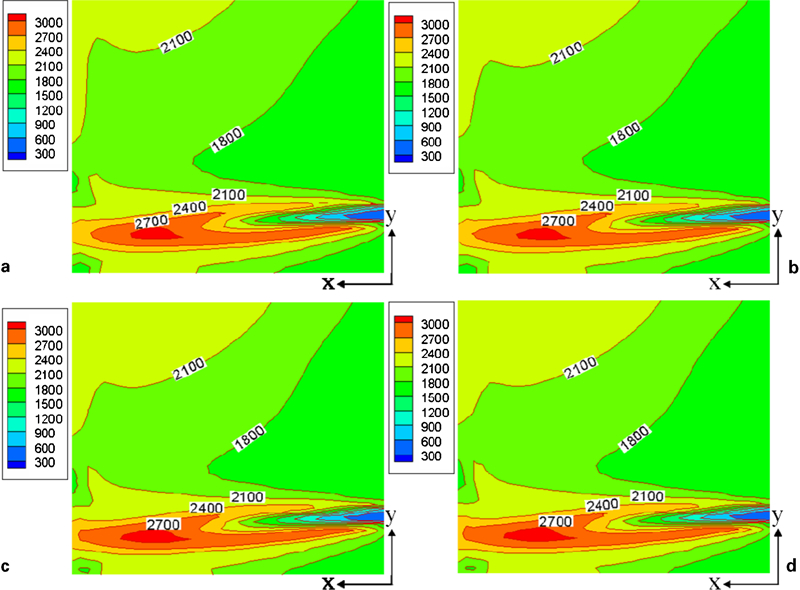
Gas temperature distributions in X–Y section with different inlet velocities of oxygen (K)
Effect of oxygen purity
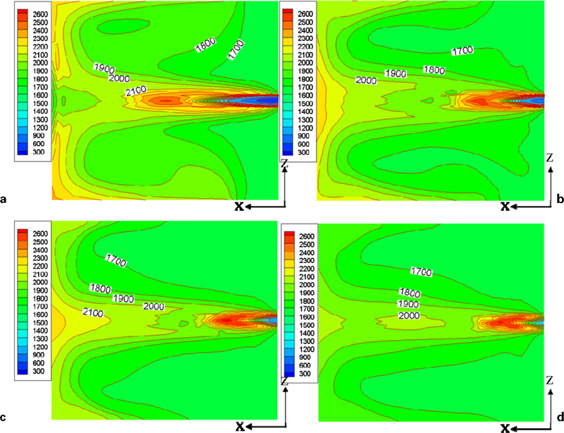
The COREX process normally operates with pure oxygen; however, because it is costly, we attempted to study the performance of COREX using impure oxygen (a mixture of oxygen and nitrogen). Figure 13 shows gas temperature distributions in the X–Z section before the tuyere with different oxygen purities. The gas temperature profiles were similar, except when the peak temperature dropped from approximately 2700 to 2550 K when oxygen purity was reduced from 99·5 to 85%. However, the nitrogen absorbed and carried much heat, and char combustion released less heat due to the decrease in oxygen purity. As a result, the high temperature domain above 1950 K shrank with the reduction of oxygen purity. Apparently, the purity of oxygen has great influence on gas temperature of raceway.
Gas temperature distributions in X–Z section with different oxygen purities (K)
Effect of oxygen temperature
The gas temperature decreased markedly when oxygen purity was reduced, so in order to ensure the demanded temperature inside the raceway was achieved, the oxygen should be preheated. Figure 14 shows gas temperature distribution in the X–Z section before the tuyere with oxygen purity of 80% at different temperatures. When the oxygen temperature was increased from 300 to 1200 K, the gas temperature profiles changed and the peak temperature increased from 2400 to 2600 K. Meanwhile, the peak temperature domain moved from the centre domain to the domain near the tuyere, which would increase the probability of the tuyere burning out. We can therefore conclude that preheating oxygen is not advisable for increasing the temperature inside the raceway with oxygen purity of 80%.
Gas temperature distributions in X–Z section with oxygen purity 80% at different temperatures (K)
Conclusions
In this work, a three-dimensional mathematical model was developed to depict the gas–char two phase flow and combustion in a COREX raceway. The flow/combustion phenomena in the raceway were simulated considering the effects of operating parameters such as oxygen velocity, purity, and temperature. The gas–char flow and combustion characteristics in the raceway were obtained at different operating parameters, which could provide theoretical basis for optimisation of operating parameters and further research of COREX process. The main conclusions are summarised below.
The high speed gas exiting the tuyere formed a central jet and a large scale recirculation, where char and oxygen mixed rapidly and uniformly. The residence time of particles was approximately 0·5–1·5 s in the recirculation regions, more than that of other regions due to the recirculation of particles with gas flow. It is beneficial for the combustion of char.
The temperature of the gas in the core of central jet region was low, which would be helpful for protecting the tuyere from burning out. In the region beside the central jet, the gas temperature was relatively uniform, ranging from 1800 to 2100 K. CO mass fraction was more than that of CO2 and O2, because the char in the raceway was abundant for combustion. According to the temperature distribution, the tuyere could be set in a right place to protect tuyere from burning out.
The oxygen inlet velocity and purity had a significant effect on combustion phenomena in the raceway. The high temperature domain above 1950 K enlarged with the increase of inlet oxygen velocity, and shrank when oxygen purity was reduced. The decrease of inlet oxygen velocity did not reduce the peak temperature; however, it was reduced accordingly with the decrease of oxygen purity. The peak temperature dropped from approximately 2700 to 2550 K when oxygen purity was reduced from 99·5 to 85% in the X–Z section before the tuyere. An inlet oxygen velocity of 175–185 m s−1 and an oxygen purity of 80–90% are recommended for the protection of the tuyere and supply of enough high temperature reducing gas.
With the increase of temperature of 80% purity oxygen from 300 to 1200 K, the peak temperature increased from 2400 to 2600 K, and the peak temperature domain moved from the centre to a place near the tuyere in the X–Z section. For this operating condition, the tuyere would burn out more easily. Therefore, preheating the oxygen is not recommended for increasing the temperature inside the raceway.
Footnotes
Acknowledgements
This work was supported by the National Natural Science Foundation of China (grant no. 50934007) and the basic theoretical fund of the Metallurgy Engineering Research Institute of USTB.