
Abstract
At the thin slab caster of Tata Steel, IJmuiden, mild cooling mould powders were introduced with the aim to control the mould heat transfer during casting. These mild cooling mould powders are characterised by specific values of basicity, solidification point and chemical composition. Application of these mould powders resulted in a redistribution of mould heat transfer during casting, i.e. a reduced and more stable mould heat transfer in the critical upper part of the mould and an increased mould heat transfer in the lower part of the mould. The average mould heat transfer and hence the shell thickness at mould exit are comparable to the standard powder. The application of mild cooling mould powders also resulted in improved solidification behaviour of the steel shell. A thinner chill zone with smaller thickness variations was observed. Furthermore, it was found that the mould taper required optimisation to match the changes in shrinkage behaviour to ensure uniform solidification. The use of mild cooling powders was observed to give an increase in mould friction. Mould thermal monitoring indicated that the solid slag films fractured (sheeting) in the upper part of the mould. However, no operational problems were reported, which indicate that the first 200 mm under the steel meniscus is essential for initial solidification and for the formation of a homogeneous steel shell. All these findings can be understood by considering the crystallisation properties of the mould slag, which include the cooling rate. Mild cooling has been shown to provide uniform heat transfer and adequate lubrication for high speed thin slab casting.
Introduction
Mould powders significantly affect the stability of the continuous casting process of steel at all casting speeds. The main functions of the mould powder are to provide strand lubrication and to control the mould heat transfer in the horizontal direction. At higher casting speeds associated with thin slab casting, the role of the mould powder is even more important.
The thin slab caster at Tata Steel, IJmuiden (Direct Sheet Plant, DSP), started production in 2000. Liquid steel is produced in the adjacent Basic Oxygen Steelplant (BOS) no. 2 and is treated in a ladle furnace. The caster has one strand and is equipped with a funnel shaped mould, a specially designed submerged entry nozzle and an adjustable multiple pole electromagnetic brake. The mould level is measured using a radiometric system. Liquid core reduction decreases the slab thickness from 90 to 70 mm. The designed production level is 1·3Mt/year of coils. The layout of the DSP is given in Fig. 1.

Layout of Tata Steel DSP
The maximum operational casting speed is 5·8 m min−1, and the average value is over 5·4 m min−1. Steel grades produced at the thin slab caster are mainly low carbon (LC) and high strength low alloy grades. The maximum sequence length is 10 ladles, which is equivalent to >12 h uninterrupted casting.
At Tata Steel, a project was started within the framework of the Materials innovation institute, Delft University of Technology, with the aim to develop mould powders suitable for high speed thin slab casting with a maximum casting speed of up to 8 m min−1. For this work, a fundamental understanding and quantification of the melting and solidification behaviour of mould slag as well as the mould powder functions were required.1
Mould powders with mild cooling properties were introduced in order to control the heat transfer between the solidifying steel shell and the mould copper plates (horizontal heat transfer). These powders show specific values of basicity (CaO/SiO2) and solidification point, promoting the crystallisation of cuspidine (3CaO.2SiO2.CaF2).2, 3 Some specifications of the mild cooling mould powder (mould powder P) are summarised in Table 1, together with the specifications of a standard mould powder for thin slab casting (mould powder A, reference).
Mould powder design
Various plant trials with mild cooling mould powders have been performed at the DSP.4 Results of these trials and several aspects of mild cooling will be described in more detail.
Mild cooling during thin slab casting
During continuous casting, the mould heat transfer in the horizontal direction reaches its maximum just under the meniscus (20–50 mm). This area can be considered as the most critical part in the casting process with respect to the formation of surface cracks in the just formed shell and the occurrence of thermal wear of the mould copper plates.5
Various plant trials with mould powder P were performed on LC and high strength low alloyed steel grades at casting speeds of up to 5·8 m min−1. Based on the condition of the DSP caster and the stability of the casting process, increased casting speeds, i.e. >6·0 m min−1, were not possible.
Compared with the standard practice based on powder A, the melting performance showed a comparable slag pool thickness (i.e. between 4 and 6 mm) with no intermediate (sinter) layers and a comparable or even less rim formation. The powder consumption increased from the standard values of ∼0·05 kg m−2 to values ∼0·07 kg m−2 and even 0·08 kg m−2 at casting speeds between 5·2 and 5·6 m min−1. The increased consumption can be understood by considering the decreased slag viscosity of mould powder P.
Trials with powder P showed a redistribution of mould heat transfer in the horizontal direction. A reduced mould heat transfer in the critical upper part of the mould was found together with an increased mould heat transfer in the lower part of the mould. The total mould heat transfer and hence the shell thickness are roughly the same. The redistribution of local mould heat transfer as found during the trials is very favourable for continuous casting, in particular for demanding casting processes like thin slab casting at increased casting speeds.
The mechanism will be explained in this paper. A schematic illustration of the mould heat transfer during casting is given in Fig. 2.
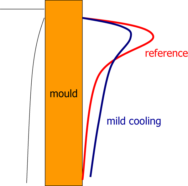
Redistribution of local mould heat transfer during casting as found during plant trials at thin slab caster: mould powder P, mild cooling
In general, the stability of the thermocouples in the upper part of the mould (first two rows) increased. During most trials, the stability of the lower thermocouples decreased and indicated breaking of the solidified slag film.
The mould level fluctuations slightly increased by 10% or less and were found to be affected by taper settings and strand friction during casting as well as the condition of the casting machine and tunnel furnace. In particular, the alignments of the segments (caster) and rolls (caster and furnace) are considered to be important subjects.
The strand friction increased by a maximum of 15% when applying powder P. This can be understood by the increased crystallisation tendency and consequently the reduced lubrication properties of the slag film. The current operational window of strand friction at the DSP, based on mould powder A, was sometimes exceeded, but no operational problems related to strand friction and casting stability were reported. It should be noted that the strand friction, as observed during all the trials, is also affected by the taper settings, the intensity of the cooling water (secondary cooling) at the caster and the condition of the continuous casting machine (alignment of segments).
The slab surface temperature increased with a maximum of 25°C. This phenomenon is not fully understood yet. It has been suggested that the effectiveness of secondary cooling is significantly affected by the presence of oxidation layers or scale built up on the slab surface.5 The oxidation layers can be a result of the interaction between the steel surface and the mould slag. The presence of fayalite (2FeO.SiO2 or Fe2SiO4), formed during this interaction, will enhance scale formation.6 Previous work at the thin slab caster showed the effects of mould powder on scale formation and scale build-up; the role of fayalite was clearly indicated.1 The slab surface showed good quality with no surface cracks or other defects. The oscillation marks were shallow and straight.
Surprisingly, it was also found that the effects on mould heat transfer (redistribution), strand friction and consequently mould level fluctuations are reduced using a previous mould powder with a reduced basicity and reduced crystallisation tendency. When the sequence starts with mould powder A, followed by mould powder P, the values obtained on mould heat transfer, strand lubrication and mould level fluctuations are less characteristic but are still significant. These effects are more profound when a sequence starts with a mild cooling powder, i.e. powder P. It is suggested that a previous mould powder or remnant of a previous powder forms an intermediate layer in the slag film, located between the mould copper plates and the slag film, as formed by the mild cooling mould powder. The intermediate layer will act as a coating.
It can be concluded that a further increase in casting speed is possible and realistic when applying mould powder P. It should be noted, however, that the condition of the casting machine and the tunnel furnace are very important subjects for high speed casting, with special requirements on the alignment of segments and rolls.
Characterisation of slab samples
Slab samples, obtained during the plant trials, were characterised using microscopic techniques. This part of the work was performed in close collaboration with Sumitomo Metal Industries. Work concentrated on the investigation of the chill zone and the thickness of the solidified shell for both casting practices (standard and mild cooling).7 The samples were obtained just after passing the pendulum shear, i.e. after casting and secondary cooling but before entering the tunnel furnace.
It was found that application of a mould powder with mild cooling properties resulted in a thinner chill zone with less thickness variation on one of the wide faces. The results suggest that the heat extraction during mild cooling was less intense and that the heat flux is distributed more homogenously across the wide face. Note that the other wide face showed less significant effects of mild cooling. Researchers at Posco reported differences in mould heat transfer at the wide faces.8
Investigations at Sumitomo revealed less thickness variations of the solidified shell after mild cooling, the shell thickness being roughly the same.
An illustration of a slab sample is given in Fig. 3.
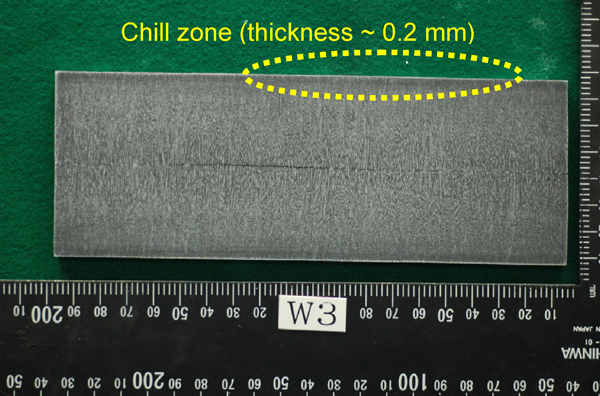
Slab sample for microscopic investigations; solidified structure
Heat flux ratio and taper settings
Introduction
Wünnenberg reviewed various aspects of mould heat transfer during continuous casting.9 One subject is the interaction between the mould heat transfer at the wide and narrow faces, observed at a thin slab caster. It was concluded that an increased mould heat transfer at the wide faces will be followed by shrinkage of the shell, which will lead to an increased thermal resistance and finally a decreased mould heat transfer at the narrow faces. Based on this mechanism, a decreased mould heat transfer at the wide faces will result in an increased mould heat transfer at the narrow faces. The work underlines the importance of the contact between the shell and the mould. Adequate taper settings and mould slag design, i.e. the slag film properties, are the main factors to achieve a controlled mould heat transfer during casting. In addition, the copper wall thickness and the amount and speed of the mould cooling water are considered to be less important parameters.
Pleschiutschnigg and co-workers developed the concept of the autopilot for automatic taper control and regulation of the casting speed at CSP plants.10 Based on the heat flux for both wide and narrow faces, the taper settings (narrow faces) during casting are controlled with the aim to keep the casting process within a window of preferred or ideal casting conditions. A main focus within this concept is the reduction in longitudinal facial cracks. For the taper settings, the heat flux ratio was introduced, which is defined as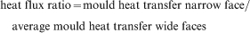
Plant observations
The heat transfer properties of mild cooling mould powders, as observed during plant trials at the DSP, were investigated by evaluating the average mould heat transfer of the wide and narrow faces based on mould cooling water data and local thermocouple data.
As described before, casting trials with mild cooling powders resulted in a redistribution of local mould heat transfer at the wide faces. The average mould heat transfer at the wide faces remains roughly the same or shows some increase compared to the reference situation (powder A). For the narrow faces, it was found that the mould heat transfer (based on mould cooling water data) shows a significant decrease with lower and more stable local temperatures. A decreased mould heat transfer at the narrow faces will result in a thinner shell compared to the wide faces of the mould.
A general overview of the average heat transfer for all the mould faces during a plant trial with a mild cooling powder (powder P) is given in Fig. 4. During the sequence, the mould powder was changed from the reference material (powder A) to the mild cooling practice (powder P). The trial was performed at a casting speed of 5·4 m min−1.
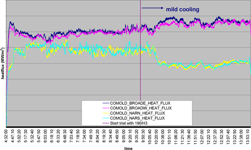
Average mould heat transfer (mould cooling water) during mould powder trial; DSP caster, v c = 5·4 m min−1
The findings on mould heat transfer can be understood since the mild cooling properties produce a thinner shell in the upper part of the mould. Referring to the wide faces, the contact between the thinner solidified shell and the mould improves, which finally results in an increased mould heat transfer and shell thickness in the lower part. Consequently, shrinkage of the shell will occur, which leads to a decreased contact between the shell and the mould at both narrow faces. A decreased contact results in an increased heat resistance and in lower values for mould heat transfer and shell thickness at the narrow faces.
The heat flux ratio decreases from ∼0·8 to ∼0·6 as a result of the mild cooling practice. This phenomenon can be explained by the significant decrease in mould heat transfer at the narrow faces compared to that at the wide faces.
As a consequence, the mild cooling practice, as applied during thin slab casting, requires increased taper settings at the narrow faces of the mould. By doing so, the contact between the strand and narrow faces will improve, the mould heat transfer at the narrow faces will increase (less thermal resistance) and the thickness of the as solidified shell will increase as well. Consequently, the overall heat transfer and shell thickness of the slab will be more uniform, which is very advantageous to the reduction in longitudinal facial cracks in the corner areas of the wide faces.
Plant trials with mild cooling mould powders were carried out using increased taper settings at casting speeds of up to 5·7 m min−1. The taper settings were increased from 1·1–1·2 to 1·4%. An additional tool for the evaluation of these trials is the shape of the narrow faces during casting, as observed at the end of the caster. The caster data showed increased values of the heat flux ratio and a comparable shape for the narrow faces of the slab, indicating an increased uniformity of mould heat transfer and shell thickness around the perimeter of the slab. Longitudinal facial cracks were not observed.
Temperature variations
Plant trials with mild cooling mould powders revealed patterns of temperature variations (mould thermocouples) in the upper part of the mould. Normally, these temperature variations are only observed in the lower part of the mould. A description of this phenomenon with a proposed mechanism is given below.
Introduction
Several investigations on slab casters report a cyclic pattern of temperature variations. These are more commonly seen in the lower half of the mould but have occasionally been observed higher in the mould.11, 12 The pattern of sawtooth-like temperature variations is mainly observed when using mould powders with an increased basicity (CaO/SiO2 = 1·6) and results sometimes in a crossover of the sticker breakout detection thermocouple signals. In general, false sticker alarms are generated, but occasionally sticking and breakouts can actually occur. It is suggested that the temperature variations can be associated with the breaking of the solid crystalline slag film during casting. The crystalline nature of the slag film, which includes the presence of pores and small cracks, is an important condition for breaking. Furthermore, relations with the thickness of the mould wall are reported as well; a thinner mould wall will show a decreased hot face temperature and an increased local heat transfer, which affects crystallisation. Finally, this will result in more temperature variations. Up to now, no direct evidence such as slag film samples has been reported in support of the proposed mechanism.
Evaluations at a medium thin slab caster (LC and stainless steels) revealed thermal fluctuations, associated with mould level fluctuations, and incidentally, with fracturing and shearing of the solid slag film in the lower half of the mould. As before, the properties of the crystalline slag film are suggested to play an important role, but actual mould powder properties are not mentioned.13
Evaluation of plant data obtained at a thin slab caster at Trico Quality Strip Production (QSP) process showed an incidental pattern of regular oscillations of the thermocouples, which can most likely be associated with breaking of the slag film, followed by refilling. However, no detailed information on slag properties and casting conditions has been given.14, 15
The authoritative work of Hooli, based on stainless steel continuous casting, describes slag films that consist of several sublayers, voids and pores.16 Very long residence times (several hours) for the slag films are reported. The slag film (or at least a part of it) adheres or even sticks to the mould wall. Furthermore, the process of devitrification is described as an important mechanism for slag crystallisation. Crystallisation of the slag film results in decreased values for mould temperatures and mould heat transfer. Based on thermocouple signals and some slag film samples, evidence of incidental fracturing of the films was reported.
The rupture strength (or elongation stress) of slag films was measured using laboratory scale equipment at 1200°C.17 The slag films were based on three commercial mould powders and were prepared in the laboratory. For these ‘synthetic’ film samples, it was concluded that the elongation stress increases with increasing thickness of the slag film, with decreasing temperature and with decreasing NBO/T ratio (a measure of the depolymerisation of the silicate network), i.e. as the slag film becomes more glassy and less crystalline. Like other parameters, attempts were made to relate the elongation stress to the structure of the slag (network), assuming that there will be a correlation between the thermophysical properties and the slag structure.18
Plant observations: standard mould powder
When casting with the standard mould powder A at the DSP, a pattern of temperature fluctuations (between 20 and 30°C) can be observed in the lower part of the mould, around rows 7 and 8 of the thermocouples (650–750 mm under the steel meniscus). Most likely, these fluctuations are related to the breaking of the slag film. At this location in the mould, the slag films are assumed to be completely solid with a distinct crystalline structure.
As described previously, slag films sampled under the mould of the DSP (standard mould powder) showed breaking of the slag films in transverse and longitudinal directions. Breaking in the transverse direction can happen in the lower part of the mould or just under the mould. Breaking in the longitudinal direction occurred along a line of bubbles, as present in the slag film, and is expected to happen in the mould during casting. If the slag film fractures in the longitudinal direction, the proposed mechanism is sheeting.12, 19
Plant observations: mild cooling practice
Plant trials with mild cooling mould powders resulted in a redistribution of local mould heat transfer and in increased friction during casting. Both phenomena can be related to the solidification and crystallisation properties of the mould slag.20 During the trials, temperature variations (with sometimes large variations of 20°C and incidentally up to 50°C) were present around rows 2 and 3 (>200 mm under the meniscus) or in row 4 (>350 mm under the meniscus). The variations around rows 7 and 8 (650–750 mm under the meniscus) were present as well.
Breaking of the slag film occurred in the upper part (row 4) and lower part (row 8) and resulted in an increased temperature at these positions, followed by a gradual temperature decrease. Breaking of the slag film always occurred, at least at one position. In many cases, casting using mild cooling mould powders resulted in an extra set of temperature variations present in the upper part of the mould.
During all mild cooling mould powder trials, no stickers or break outs occurred, no extra wear or deterioration of the mould plates was seen and slab surface quality was found to be good.
The temperature variations, in particular the variations in the upper part of the mould, were found to be influenced by the following variables:
previous mould powder: use of the standard mould powder (mould powder A), i.e. a powder with a lower crystallisation tendency before using a mild cooling mould powder, resulted in less, or even no, temperature variations in the upper part of the mould
position in the mould: the parallel part of the mould showed the most stable thermocouple signals, followed by the funnel area; the transition area between the parallel part of the mould and the funnel area showed more temperature variations
casting speed: an increased casting speed sometimes resulted in temperature variations at a lower position in the mould
meniscus fluctuations: the temperature variations in the upper part of the mould can sometimes be associated with severe meniscus variations due to bulging, waves, etc., as detected by the mould level control system.
Figure 5 gives an overview of the mould signals during casting at 5·7 m min−1, measured at the transition area between the parallel part of the mould and the funnel, and showing very severe disturbances.
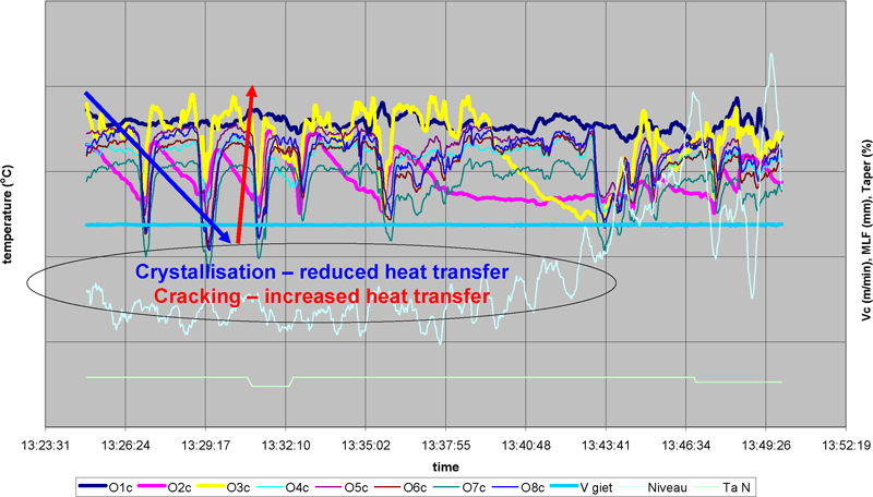
Thermocouple signals from DSP caster (parallel/funnel area), v c = 5·7 m min−1: (left axis) temperature (°C); (horizontal axis) time; and (right axis) casting speed (m min−1), mould level fluctuations (mm) and taper (%)
The sawtooth pattern (pink) is located at row 2, ∼200 mm under the meniscus. In general, the temperature signals for all columns show that the lowest point of a temperature cycle is ‘transported’ downward within ∼10 s, which can be related to the casting speed. It can be concluded that the film breaks around row 2, 3 or 4 and is transported together with the moving strand.
Analysis of slag films
Inside mould, DSP
As described previously, slag films from standard powder A were sampled from inside the mould at the DSP caster, immediately after casting.1
The films were located ∼50 cm below the steel meniscus; the thickness of the films is between 200 and 300 μm. Almost all films show a dominant layer of cuspidine crystals (3CaO.2SiO2.CaF2 or Ca4Si2O7F2) in a glass matrix and an amorphous layer. The crystalline layer is located at the mould side; the amorphous layer is present at the strand side and is probably formed from the liquid phase, immediately after casting.
Surprisingly, several samples of the standard powder clearly showed the crystalline layer present in the middle of the slag films and surrounded by two layers of amorphous material. One amorphous layer is located between the crystalline layer and the strand and one layer between the crystalline layer and the mould side. An illustration is given in Fig. 6a ; in this figure, the crystalline layer is denoted as II. This crystalline layer appeared to be fully comparable with crystalline layers located at the mould side, as observed in the other slag films. Furthermore, samples with the crystalline layer in the middle of the film showed the start of crystallisation in the amorphous layer (devitrification) as present between the crystalline layer and the mould (Fig. 6b , layer I).
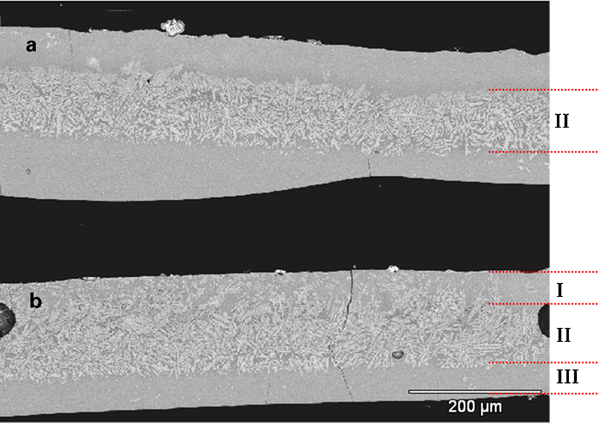
Slag films, sampled from inside mould, showing crystalline layer in a middle of film (II) and b start of crystallisation at mould side (I)
It is suggested that the solid part of the slag film fractured and came loose from the copper mould. Subsequently, fresh liquid slag entered the gap between the crystalline film and the copper mould and solidified as an amorphous material. After some time, crystallisation of the newly formed amorphous layer at the mould side started. It is obvious that this process will result in variations in temperature and local mould heat transfer.
Under mould, DSP
Slag films sampled under the mould of the DSP showed breaking and sheeting of the slag films in the transverse and longitudinal directions. Sheeting in the longitudinal direction occurred along a line of bubbles and is expected to happen during casting.19
Summary of findings, hypothesis and proposed mechanism
It is obvious that the temperature variations associated with breaking and sheeting of the solid slag film are enhanced by the solidification properties of the mould slag. An increased solidification point and an increased crystallisation tendency will result in variations at higher positions in the mould. Deformation of the solid and crystalline slag films due to the shape of the mould (parallel – funnel) further enhances these variations.
There is some similarity with previous work on the formation of star cracks. It is proposed that decreased liquid lubrication, i.e. running out of liquid in the slag film, enhances the formation of surface cracks and may result in fracturing of the solid slag film in the lower half of the mould.21
The cyclic temperature variations in the upper part of the mould can be controlled and suppressed using a previous mould powder with a lower crystallisation tendency. Both the findings of Hooli16 and those recorded in this project revealed that the residence time of the slag film or at least the part of the film in contact with the mould is very long (up to 10 h or more).1
It is suggested that the slag film formed by a previous mould powder acts as a coating layer with a very long residence time. This coating diminishes the temperature variations, resulting from fracturing of the neighbouring slag film. An increased casting speed (within the actual operational window of 5·8 m min−1 at most) will only result in breaking of the slag film at a somewhat lower position in the upper half of the mould. This can be understood by the increased mould heat transfer at increased casting speeds and consequently by the delayed solidification and crystallisation of the slag film.
Surprisingly, no operational problems related to the fracturing of mould slag and no surface cracks have been reported during all trials. This indicates that the first 200 mm under the steel meniscus is essential for initial solidification and for the formation of a homogenous steel shell, more precisely the top shell. This can be clarified by considering the thickness of the solidified shell in the upper part of the mould, i.e. at a casting length of 200 mm.
A general approach to calculate the shell thickness during casting is given in equation (1)
After the breaking of the slag film in the upper part of the mould, two underlying mechanisms will happen simultaneously:
the hole in the slag film will be refilled with fresh mould slag. This slag solidifies, resulting in amorphous material and hence in increased local mould heat transfer. Subsequently, the slag film crystallises and will break again
the broken part of the film moves downward with the strand.
A schematic illustration of the temperature variations in the upper part of the mould is given in Figs. 7 and 8:
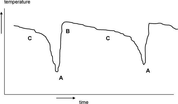
Schematic illustration of mould temperature variations (upper part): time between points A is 2 min or more
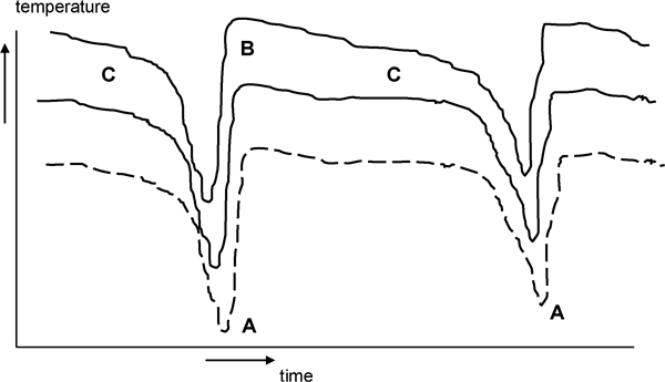
Schematic illustration of mould temperature variations (upper part), followed by lower thermocouples (dashed curve)
at stage A, the slag film breaks or shears; resulting in a sharp increase in the mould temperature and the local mould heat flux. Next, the gap is refilled with liquid slag
at stage B, the gap is filled with fresh mould slag and after quenching followed by crystallisation of the amorphous slag (devitrification)
at stage C, crystallisation of the slag film results in a gradual decrease in temperature and mould heat flux. Pores will be formed due to crystallisation; furthermore, the shear force between the solid slag film and the moving strand will result in the formation of stresses and probably cracks in the crystalline material. The presence of pores and cracks will result in a further sharp decrease in the temperature and mould heat flux.
The temperature signals in almost all columns show that stage A is ‘transported’ downwards within 10 s.
Next steps
The mild cooling mould powder was initially designed for a maximum casting speed of 8 m min−1. During this project, the maximum operational casting speed was 5·8 m min−1. Although no operational problems related to the temperature variations and associated with sheeting of slag films were reported, it was proposed to decrease or suppress these variations for reasons of operational stability. A decreased crystallisation tendency of the mild cooling mould powders will result in a less rigid slag film and in decreased or no cyclic temperature variations in the upper part of the mould. For plant operations with casting speeds of up to 6·0 m min−1, a slight decrease in basicity or the solidification point was suggested while keeping all the other variables constant.
Furthermore, it is proposed to measure the rupture strength or elongation stress of slag films for thin slab casting at increased temperatures.17 Slag films from inside the mould are preferred; however, the measurements can start with slag films prepared at the laboratory. It is highly recommended to relate the physical properties to the structure of the mould slag.
Crystallisation of mould slag: effects of cooling rate
Introduction
At Carnegie Mellon University, Pittsburgh, USA, single and double hot thermocouple techniques (SHTT and DHTT) were developed for direct observation and measurement of mould slag crystallisation.24, 25 The SHTT and DHTT techniques enable in situ observation and quantification of melting and solidification processes of transparent slags, applying high cooling rates (SHTT) and large temperature gradients (DHTT). This work was continued by researchers at TU Bergakademie Freiberg, Germany, and IRSID.26, 27 In the work at TU Freiberg and Carnegie Mellon University, it is assumed that the cooling rates in continuous casting are in the range from < 1 to 20°C s−1 and even 100°C s−1. The techniques at both institutes roughly cover a major part of this range.
The effects of the cooling rate on several slags and a mould powder were studied.28 Results can be summarised in continuous cooling transformation (CCT) diagrams (based on continuous cooling experiments) or time temperature transformation diagrams (based on isothermal experiments).
A conclusion of these researchers is that crystallisation of the mould slag can be described by nucleation and growth of individual crystals in an undercooled liquid. There is no specific crystallisation temperature for a mould flux but a range of temperatures, dependent on experimental conditions, i.e. cooling rates. The start of crystallisation will shift to lower temperatures with increasing cooling rate.
Each phase formation needs time for nucleation and required diffusion of the components. If the time for diffusion decreases (by increasing cooling rate), the undercooling must increase to make crystal formation kinetically possible. At very high cooling rates, solidification occurs into a glass or a partly crystalline phase. As the slag can undercool significantly below its equilibrium liquidus temperature, the phase diagram, if existing, does not give adequate information on the kinetic conditions under which crystallisation will occur.
The crystallisation rate (nucleation and growth) increases with decreasing temperature because the thermodynamic driving force increases. On further cooling, this influence is counteracted by the decreased atomic mobility, also resulting in an increased viscosity.29 Note the nose temperature (T
nose) and nose time (t
nose) of the C curve. This point indicates the highest cooling rate at which crystallisation occurs. An estimation of T
nose can be given as
The critical cooling rate, i.e. the rate of cooling to avoid crystallisation, can be estimated by
Tsutsumi et al. investigated the surface roughness of slag films with a confocal scanning laser microscope using cooling rates of up to 30°C s−1.30 They concluded that the surface roughness is mainly in the range between 10 and 30 μm and is caused by the crystallisation of the mould slag. The surface roughness decreases with a higher cooling rate and increases with an increase in the critical cooling rate of the mould slag. The size of the crystals at lower cooling rates appeared to be larger, resulting in an increased (larger) surface roughness.
As crystallisation not only depends on the actual cooling rate but also on the critical cooling rate, the ratio of the actual cooling rate and the critical cooling rate is defined as the normalised cooling rate r
n

No crystalline phases precipitate when the normalised cooling rate (r n) is greater than unity. The normalised cooling rate was used to investigate the relation with the surface roughness of various mould fluxes.
Experimental work
In order to investigate the effect of the cooling rate on slag crystallisation, measurements were performed at TU Bergakademie Freiberg using SHTT. The measurements started with the standard mould powder for thin slab casting (mould powder A), followed by a mild cooling mould powder (mould powder P).
For the measurements, a mould powder was heated at 600°C for 4 h. After crushing in a mortar, the material was heated at 1500°C for 1 min to obtain a homogeneous sample. Then, the sample was cooled with cooling rates of 5, 10, 20, 50, 100, 200 and 500°C min−1. During the measurements, the beginning of crystallisation was observed as well as the time at halfway crystallisation (50%) and the end of crystallisation. These measurements were repeated twice. Slag crystallisation appeared in all samples, i.e. at all cooling rates with the exception of a cooling rate of 500°C min−1 (mould powder A).
Based on the measurements, the CCT diagram was constructed from which the nose temperature (T nose) and nose time (t nose) were determined. Results are illustrated in Figs. 9 and 10.
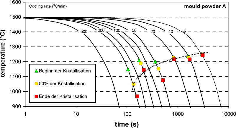
Continuous cooling transformation diagram of standard mould powder: mould powder A
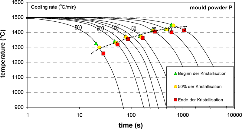
Continuous cooling transformation diagram of mild cooling mould powder: mould powder P
The experimental uncertainty in the determined values for beginning, halfway (50%) and end of the crystallisation is such that the extension of the crystallisation range in time and temperature could not be determined. Instead, the values corresponding to halfway crystallisation (50%) were used for evaluation purposes.
From these results, the nose temperature of mould powder A is estimated to be ∼900–1000°C and the corresponding nose time to be ∼100 s.
In order to calculate the nose temperature (T nose) and the critical cooling rate (r c), the melting trajectory of both powders was measured using a hot stage microscope (DIN 51730). Results are given in Table 2.
Melting trajectory
The nose temperature is in agreement with equation (2), which gives a value of 936°C. For mould powder P, the nose time lies below 10 s. The nose temperature cannot accurately be estimated but does not seem to be inconsistent with the value based on equation (2), which is 949°C.
Compared with the standard mould powder A, the mild cooling mould powder P exhibited bigger crystals during the experiments. Furthermore, the higher temperatures and the small temperature variations between start and end of crystallisation, as found for all cooling rates (up to 500°C min−1), emphasise the increased and stronger crystallisation tendency of mould powder P.
For mould powder A, the nose of the crystallisation curve is located at T nose = 936°C and t nose = 100 s. With a start temperature of 1500°C, this results in a critical cooling rate r c = 5·6°C s−1 (340°C min−1).
For mould powder P, the determination of the critical cooling rate is less accurate, since the nose is not actually determined. Using the temperature resulting from equation (2) (949°C) and an estimated t nose = 5 s, the critical cooling rate is estimated at r c = 100°C s−1 (6000°C min−1), with an estimated uncertainty of 50%.
An estimation of the cooling rate of the mould slag in the longitudinal (casting) direction at the DSP is between ∼35 and 40°C s−1. The local cooling rate, especially near the meniscus, will be considerably higher. Direct crystallisation of a mould powder during casting will not occur when the cooling rate exceeds the critical rate.
It can be concluded that especially at the start of casting, mould powder A will quench, followed by crystallisation (devitrification). Compared with the standard mould powder, however, mould powder P shows a higher value of the critical cooling rate (r c); the normalised cooling rate (r n) is estimated to be around unity or less.30 An increased crystallisation tendency and hence an increased surface roughness and interfacial thermal resistance can be expected when using mould powder P. Results of the two mould powders are summarised in Table 3.
Nose temperature and cooling rates of mould powders A and P
Conclusions
Mould powder with mild cooling properties will show a redistribution of local mould heat transfer at the wide faces of the mould, i.e. a reduced mould heat transfer in the critical upper part of the mould, and an increased mould heat transfer in the lower part of the mould while maintaining a comparable average mould heat transfer and hence shell thickness during casting. These effects are very favourable for continuous casting, in particular for demanding casting processes like thin slab casting.
Microscopic investigations of slab samples confirmed the observations on mild cooling, revealing a more homogeneous structure of the solidified steel shell, i.e. the chill zone and the shell thickness.
There is no complete breaking of the slag film in the upper part of the mould but rather partial sheeting, which is associated with the crystalline nature of the slag film.
The trials with mild cooling indicated that the first 200 mm under the steel meniscus are essential for initial solidification and for the formation of a homogeneous steel shell (top shell).
Mild cooling powders require increased taper settings due to the solidification behaviour at the wide and narrow faces. As a consequence, the overall mould heat transfer and hence shell thickness of the slabs will be more uniform, which is advantageous in order to suppress the formation of longitudinal facial cracks in the corner area of the wide faces.
All these findings can be understood by considering the crystallisation properties of the mould slag and the effects of slag crystallisation on the mould heat transfer in the horizontal direction.
Footnotes
Acknowledgements
The authors would like to thank Dr M. Hanao of Sumitomo Metal Industries and Dr J. J. Campaniello of Tata Steel RD&T for the excellent work on the characterisation of slab samples. Furthermore, thanks are due to Professor Dr Ir J. Sietsma of Delft University of Technology for the fruitful comments on the evaluation of the SHTT experiments. Part of the research was carried out under project no. MC5·05225 in the framework of the Research Programme of the Materials innovation institute (M2i), Delft University of Technology, The Netherlands (![]() ). This paper is based on a presentation at the 7th European Continuous Casting Conference (ECCC), organised by Steel Institute VDEh in Düsseldorf, Germany, on 27 June–1 July 2011.
). This paper is based on a presentation at the 7th European Continuous Casting Conference (ECCC), organised by Steel Institute VDEh in Düsseldorf, Germany, on 27 June–1 July 2011.