
Abstract
Electroslag casting with liquid metal (ESC LM) is a new technology in electroslag metallurgy. Solid ingot, hollow ingot and bimetal composite can be produced by the ESC LM process. Using both internal and external current carrying moulds for ESC LM is a new method for manufacturing hollow ingots. Liquid metal is employed directly during the ESC LM process rather than the conventional consumable electrode. The process was simulated using infinite element software ANSYS. The results indicate that the conductive path of the ESC LM process is entirely different from the conventional electroslag remelting process. There are two conductive current paths: one conductive path is transformer→external current conductive mould→liquid slag→internal current conductive mould→transformer, and another conductive path is transformer→external current conductive mould→liquid slag→molten steel pool→liquid slag→internal current conductive mould→transformer. Current density, magnetic inductive intensity, electromagnetic force, Joule heat distributions and fluid flow are concentrated on the upper area of the slag pool. In addition, the higher temperature region of the slag pool is at the upper area of the slag pool. The superheat of the molten steel pool is lower than the conventional electroslag remelting process, which favours improving the quality of the hollow ingot. Simulation of the ESC LM process will help understanding the process and choose better operating parameters.
Introduction
The electroslag technology with a liquid metal had been invented by Elmet Roll, Medovar Group in the Ukraine. 1 Recently, a similar technology of electroslag casting with liquid metal (ESC LM) for manufacturing high quality special steel ingots has been developed by Dong et al. 2
The ESC LM process is a new technology developed on the basis of conventional electroslag metallurgy technology. When comparing with traditional electroslag metallurgy technology, an ingot manufactured by ESC LM maintains the excellent performance of a conventional electroslag remelted (ESR) ingot, and in addition, the production efficiency of the process is increased, production cost decreased and the production cycle shorted. The ESC LM method of using liquid metal directly does not require the preparation of consumable electrode. A current carrying mould as well as a continuous withdrawal mechanism has been adopted, which can increase the production efficiency greatly. The basic process for ESC LM can be described as follows. First, liquid slag is melted by a slag melting furnace and poured into the current carrying mould, and then, the power is switched on. Next, the liquid metal, prepared in a melting furnace, is poured through the molten slag, and once solidification commences, the ingot is withdrawn from the mould continuously. In the process variation studied in this paper, the mould is in the form of a ring, i.e. inner and outer walls, used for the production of hollow ingots for tube manufacture. The system is shown schematically in Fig. 1.
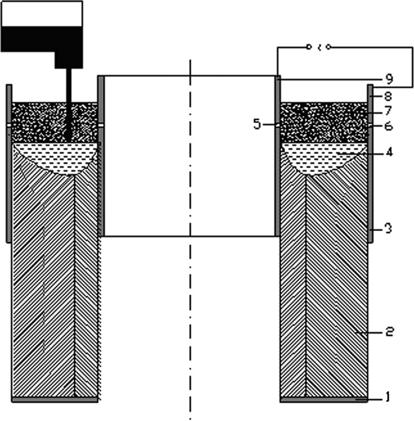
Schematic diagram of ESC with liquid metal of hollow ingots
Currently, adopting mathematic models to describe the process has been the common method for studying process technology, as this is an easy and quick method and is favourable for saving the cost and time of experiments. After traditional electroslag technology was born, it appears that many mathematic models were used to describe the process, analyse the essence of electroslag remelting and formulate the proper process parameters. A more accurate and comprehensive model had been developed for the electroslag remelting process by Patel et al. 3 The basic principles, i.e. the continuity equation and the equation of motion, were adopted to describe the fluid flow phenomena in the electroslag refining process by Dilawari and Szekely. 4 Although the electromagnetic equations had been considered in their study, buoyancy body force had been neglected. Electromagnetic force as well as buoyancy body force had been taken into account in their further research about current–voltage relationships and heat generation patterns in the electroslag refining process. 5 The influence of frequency on current density has been studied by Wang and Li, 6 which develops an understanding of the effect of frequency on the ingot quality. Another mathematical model including the electromagnetic field, fluid flow and heat transfer equation has been developed by Dong et al., 7 and in this model, the dendritic spacing has been calculated for evaluating the ingot quality. A 3-D model has been developed for simulating the remelting 120 t large ingot by Liu et al., 8 but the electromagnetic field and fluid flow existing in this process were not considered entirely. Another model for manufacturing a large ingot was developed by Dong et al. 9 based on a four-electrode configuration. In addition, a more comprehensive model has been developed by Choudhary et al. 10 All these models are for the electroslag remelting process. Owing to the newness of the technology of the ESC LM process, there is little published literature on process investigation and corresponding mathematic model development. Therefore, it is meaningful to carry out the numerical simulation of ESC with liquid metal. The ESC LM process can be used to manufacture solid ingots, hollow ingots, compound rolls, etc. The purpose of this paper is to investigate the ESC LM process for fabricating hollow ingots by simulation method, which will help us to understand the process.
Mathematic model
The technology of the ESC LM process has the advantages of not only traditional electroslag metallurgy but also the continuous withdrawal of continuous casting. The technology of the ESC LM uses direct liquid metal to pouring; therefore, it is not necessary to prepare consumable electrodes. The process of ESC LM can reduce the production cost of traditional electroslag metallurgy technology and shorten the production cycle. In addition, the possible factors of molten steel secondary pollution and refractory material pollution of the conventional electroslag remelting process in the preparation of the electrodes are reduced significantly.
A current carrying mould is adopted in the ESC with the liquid metal process. The function of the liquid slag for ESC LM is similar to the conventional electroslag metallurgy process, including heat generation and steel refining. 11 Therefore, there are electromagnetic fields, fluid flow and heat transfer phenomena during the process, and they both interact and influence each other. The physical and chemical phenomena of the process are similar to traditional electroslag remelting technology.
The work to be described is based on the following assumptions:
slag–metal boundary is presented by horizontal surfaces
quasi-steady state for pouring liquid metal
thermal exchange is negligible during molten steel flow through the liquid slag
voltage loss is only in the molten slag pool
continuity of heat flux at all the external surfaces and at the slag/metal interface
latent heat is expression as enthalpy
physical chemistry properties of steel and slag are associated only with temperature.
Electric field equation


Electromagnetic field equation

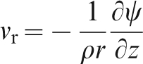
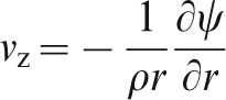
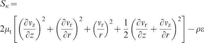
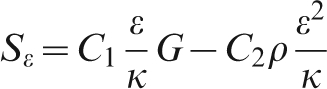
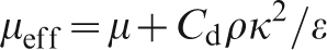
Fluid flow equation
Fluid flow, driven by electromagnetic force, buoyancy, etc., is an important phenomenon in the ESR system. The electromagnetic force field plays a major role in fluid flow. The equation of fluid flow may be given as the vortex transport equation in axisymmetric cylindrical coordinate system,
12
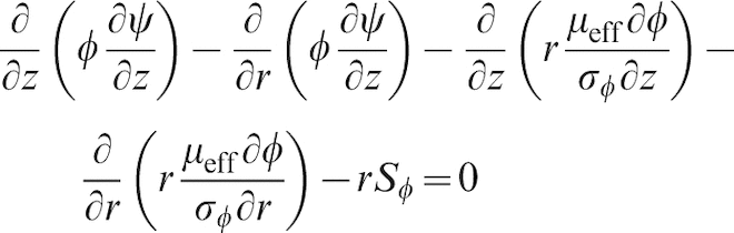
which takes the following form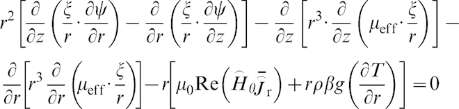


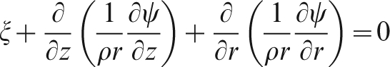
For cylindrical coordinate, vorticity ξ and stream function ψ can be defined as the following form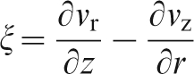
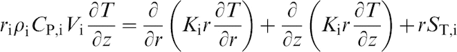
Governing equation for convection heat transfer
Through coupling the electromagnetic fields and fluid flow equations, the governing equations for temperature fields can be expressed by the following form at cylindrical coordinate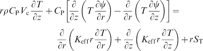
In addition, in order to understand the solidification features of the processes, enthalpy was introduced into the process.
Geometric model and essential parameter
Both internal and external current carrying moulds have been adopted for manufacturing hollow ingots, and the basic principles of this technology are shown schematically in Fig. 1. There are two conductive current paths: one conductive path is transformer→external current conductive mould→liquid slag→internal current conductive mould→transformer, and the another conductive path is transformer→external current conductive mould→liquid slag→molten steel pool→liquid slag→internal current conductive mould→transformer.
At present, it is difficult to couple simultaneously thermal, electric, magnetic, fluid flow and solidification using commercial software. Therefore, the finite element analysis software ANSYS as well as CFX was employed to simulate the ESC LM process. A three-dimensional solid model must be constructed for simulating the process, because the ANSYS software uses finite element method for solution, but the CFX software using the finite volume method. Figure 2 shows the simplified flow diagram for the computational scheme. The slag is 40CaF2–30Al2O3–30CaO. The main parameters used in this model are listed in Table 1.
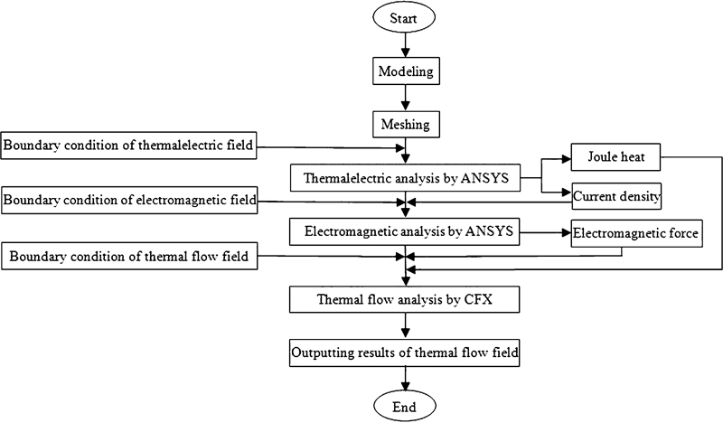
Numerical simulation process of ESC with liquid metal of hollow ingot
Geometric parameters of ESR LM process
In order to simplify the calculation, a plane of 0·15° of the three-dimensional model was erected, taking into account the axial symmetry of the system. Figure 3 shows the figure after meshing.
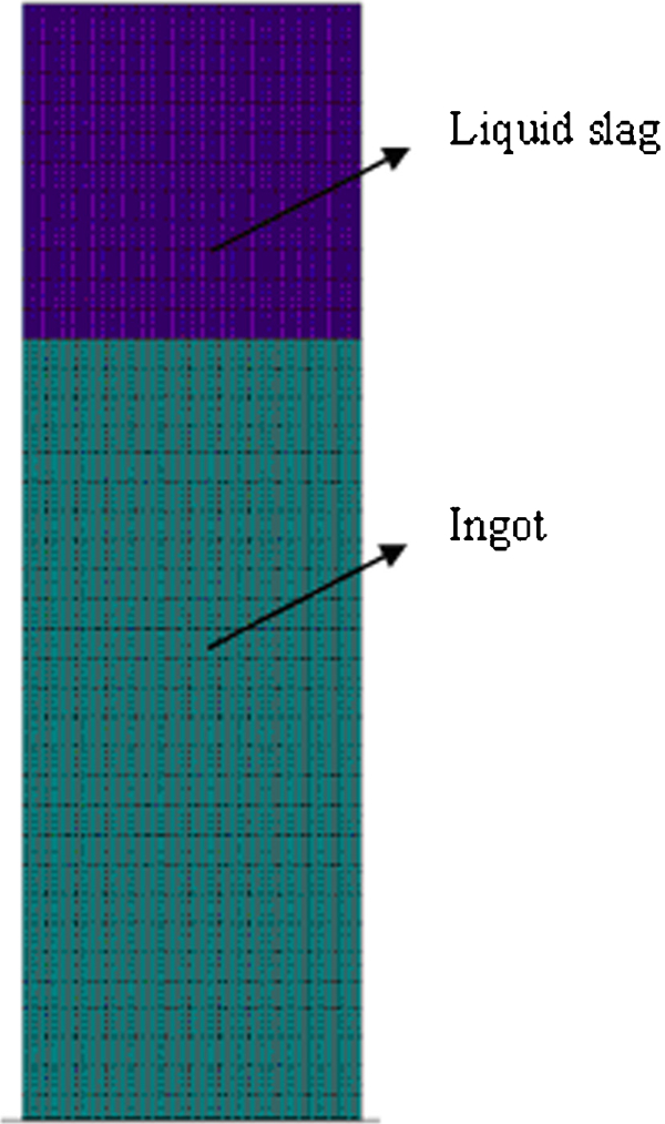
Finite element mesh generation
Results and discussion
Figure 4 illustrates the electric potential distribution in the liquid slag of the ESC LM process. It can be seen from this figure that greater and uniform electric potential gradient appears at the upper part of liquid slag, whereas it is less for the lower part of liquid slag. The features of the electric potential distribution results in larger current density at the upper part of the liquid slag (Fig. 5) and higher joule heat density (Fig. 6), which will eventually lead to the highest temperature in this region.
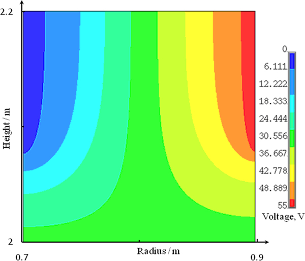
Electric potential distribution in slag pool
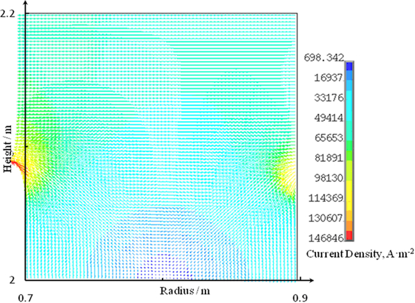
Current density distribution in slag pool
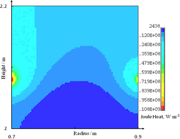
Joule heat distribution in slag pool
It can be seen from Fig. 5 that significant differences exist in the slag pool. The current density is larger in the upper part, and its direction is along the radial direction. Less current density is at the lower part of the slag pool, and its direction is along the axial direction. The largest current density is below the conductor, and its value is 1·47×105 A m−2; the least current density lies in the central region of the slag/metal interface, and its value is 698·342 A m−2 under the condition of calculation. The special structure of the current carrying mould is the main reason for the phenomena. The electrical potential is prone to pass the smaller resistance of the conductor, which is a characteristic of electricity; it is also no exception in ESC LM process. The current from the transformer is introduced into the upper part of the current carrying mould and then through the slag pool to the molten steel near the lateral mould. Afterwards, the current is through the slag pool inside the mould to the upper conductor of the internal current carrying mould and then returns to the transformer.
Furthermore, the Joule heat distribution is affected by the current distribution. The values in Fig. 6 represent the Joule heat generated by the unit volume. Joule heat is larger in the upper part of the slag pool, and the largest value is around the insulation layer. In the lower regions of the slag pool, the joule heat is less; the least value lies in the central region of slag/metal interface. This distribution characteristic is similar to the current density distribution. From the point of view of controlling steel solidification, this distribution characteristic of joule heat is favourable to the formation of shallow molten steel pool.
Figure 7 shows the magnetic induction intensity distributions of the slag pool for the ESC LM process; its direction is perpendicular to the paper. The distribution characteristic is similar to the current density distribution. The magnetic induction intensity distribution for the upper part in the slag pool is larger than the lower part. The current through the conductors leads to the magnetic field. The current increases in the upper slag pool with increasing height, which results in the increase in magnetic induction intensity with the increase of the height under the same radius condition. The trends of magnetic induction intensity in the internal mould can explain these phenomena. The largest value of magnetic induction intensity in the internal mould is 0·013176 T according to simulation results.
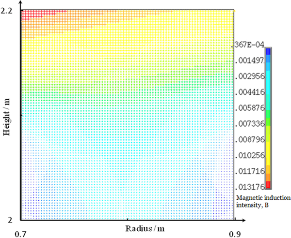
Magnetic induction intensity distribution in slag pool
The electromagnetic force distribution in the slag pool is shown in Fig. 8. The relationship between electromagnetic force and current and magnetic induction intensity complies with the left hand rule. Overall, the direction of the electromagnetic force was axial, and in the same way, it is larger for the upper part of the slag pool than the lower part. It corresponds to the current density and magnetic induction intensity. The closer from the inner mould is, the larger electromagnetic force value is in the upper area of the slag pool, and the largest value is 0·983×10−5 N according to calculation. This distribution feature tends to make the slag flow counterclockwise.
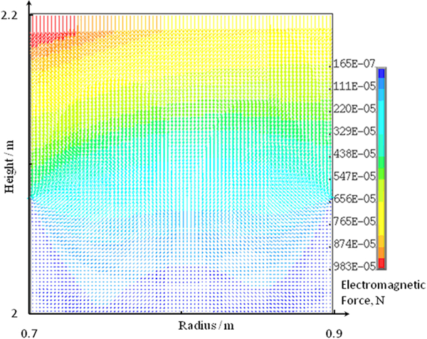
Electromagnetic force distribution in slag pool
There are two spiral vortices in the slag pool of the ESC LM process, as shown in Fig. 9; they are all in the upper area of the slag pool. The slag tends to a counter clockwise rotation near the surface of the inner mould, and the spiral vortex is rather larger and occupies most of the regions of the slag pool. However, the liquid slag tends to clockwise rotation near the external mould, and its spiral vortex is relatively small. Based on the calculation results, the velocity range of liquid slag is from 0 to 0·072 m s−1. The largest velocity of liquid slag is near the internal mould wall, and the smallest is in the centre of the spiral vortex. Heat convection is worse at the region of lower velocity and that results in larger temperature gradient and uneven temperature distribution in the slag pool, as shown in Fig. 10.
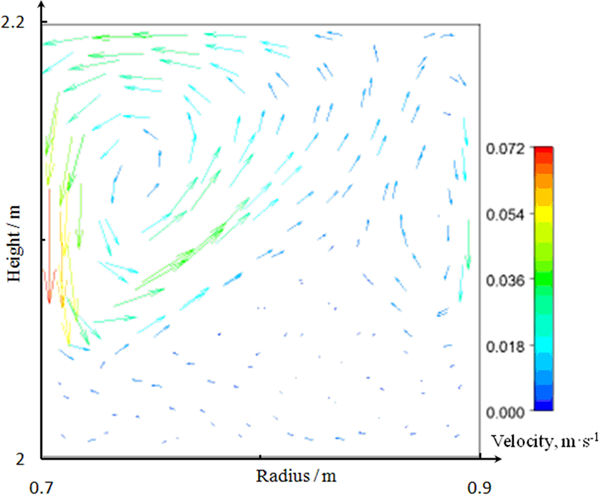
Velocity vectors distribution in slag pool
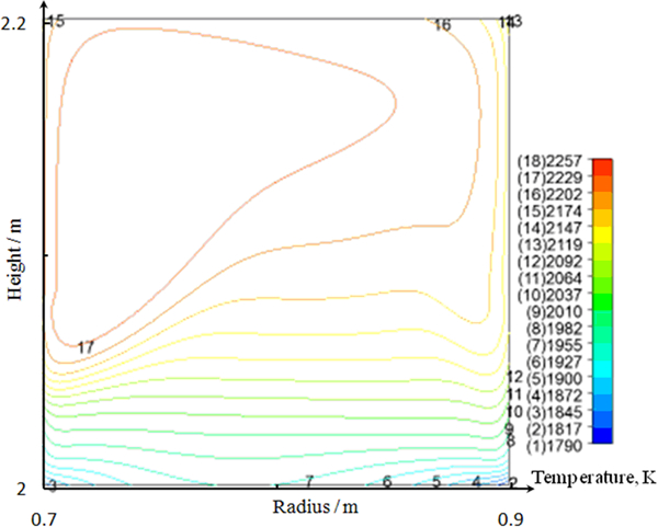
Temperature distribution in slag pool
A higher and uniform temperature distribution lies in the upper area of the slag pool; however, lower temperature and higher temperature gradients appear in the lower part of the slag pool. The interaction of magnetic force and buoyancy leads to turbulence in the upper area of the slag pool and further results in this distribution characteristic of the slag temperature distribution. Whereas, flow velocity of the slag is weak and convective heat transfer is not obvious due to less magnetic force and buoyancy.
The temperature distribution in the molten steel pool influences the ingot quality directly. It can be seen from Fig. 11 that the shape of the molten steel pool is shallow. The temperature for the inner and outer surfaces of the hollow ingot is unsymmetrical, and the inner surface temperature is higher than the outer surface under the same horizontal position. There are two aspects of this problem that have to be addressed. The first is the unsymmetrical nature of the thermal from the slag/metal interface to molten steel pool. The second problem relates to the ingot surface cooling area, and the ingot surface cooling area is larger for the outer ingot surface than inner surface. The highest temperature is 1956 K for molten steel pool, and it is 83 K higher than the pouring temperature. This may be due to heat transfer from liquid slag to molten steel pool. The superheat of the molten steel pool is lower for the ESC LM process than for the traditional electroslag remelting process. Moreover, a higher temperature in the molten steel pool provides better thermodynamic and kinetic conditions, accelerating the removal of detrimental impurities and non-metallic inclusions. In addition, the slag skin around the ingot is thin and uniform, which is favourable in producing a smooth surface on the hollow ingot.
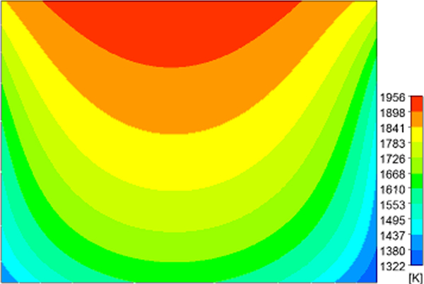
Temperature distribution in molten steel pool
Comparing the conventional electroslag remelting process, adoption of the current carrying mould in the ESC LM process makes the highest temperature region far from the slag/metal interface and decreases the heat transfer from liquid slag to molten steel pool, which avoids the existence of V shape molten steel pool, as shown in Fig. 12.
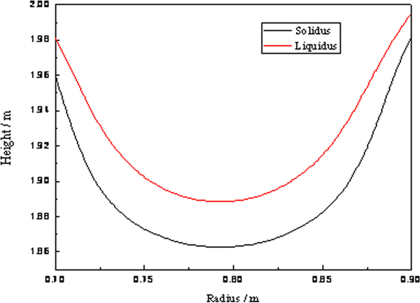
Shape of molten steel pool
Conclusions
A new technology of ESC LM for manufacturing high quality special steel ingots has been developed, in which a current carrying mould is used. In this paper, numerical modelling is used to investigate the effects in the liquid slag pool and solidification on a variant ESC LM for the production of hollow ingots. Although this work is at the early stage, the results from the modelling have given insight into the phenomena in the liquid slag pool and shown that the steel pool is shallower for ESC LM than for the conventional electroslag remelting process, which is favourable for controlling the solidification quality of the hollow ingot. The results indicate that the conductive path of the ESC LM process is entirely different from the conventional electroslag remelting process. There are two conductive current paths: one conductive path is transformer→external current conductive mould→liquid slag→internal current conductive mould→transformer, and the another conductive path is transformer→external current conductive mould→liquid slag→molten steel pool→liquid slag→internal current conductive mould→transformer. Current density, magnetic inductive intensity, electromagnetic force, Joule heat distributions and fluid flow are concentrated on the upper area of the slag pool. In addition, the higher temperature region of the slag pool is at the upper area of the slag pool. The superheat of the molten steel pool is lower than the conventional electroslag remelting process, which is favours improving the quality of the hollow ingot.
Footnotes
Acknowledgement
This work was supported by the National Nature Science Foundation of China under grant no. 50904015.