
Abstract
The objective of the present study was to simulate liquid steel flow entry behaviour into a curved billet mould when supplied by an open stream or using a submerged entry nozzle (SEN). For the SEN modelling, nozzle misalignments were considered to determine its effects on the mould flow dynamics. A three-dimensional numerical model in a Cartesian coordinate system was used. For spatial discretisation, a structured mesh was used. For the open stream, two phases (steel–air) were considered in order to study the free surface behaviour. Owing to extreme turbulence, this configuration is useful only for low quality steels. This can be eliminated using a SEN. When the SEN was employed, a multiphase system was also considered (steel–slag–air) to study the free surface stability. However, despite using an aligned SEN, non-symmetric flows are generated, which can be controlled with an appropriated inclination towards the inner radius.
List of symbols
model constant of turbulent viscosity
k–ϵ model constants
gravitational acceleration, m s−2
generation of turbulent kinetic energy due to the mean velocity gradients, kg m−1 s−3
turbulent kinetic energy, m2 s−2
kelvin temperature.

mass transfer from phase p to phase q, kg m−3 s−1

mass transfer from phase q to phase p, kg m−3 s−1
pressure, Pa
phases present at each cell
source term of mass transfer, kg m−3 s−1
time, s
temperature, °C
temperature difference, °C
x component of velocity, m s−-1
volume flux through the face
volume of cell, m3

velocity vector
Cartesian coordinate
volume fraction
phase p and phase q volume fraction respectively
face value of the qth volume fraction respectively
dissipation rate of the turbulent kinetic energy, m2 s−3
viscosity, kg m−1 s−1
effective viscosity, kg m−1 s−1
mixture, phase p and phase q viscosity, kg m−1 s−1 respectively
turbulent viscosity, kg m−1 s−1
turbulent Prandtl number for k and ϵ respectively
density, kg m−3
mixture, phase p and phase q density respectively, kg m−3
gradient operator

divergence operator
curl operator
Lapalacian operator
Introduction
It is widely known that steel quality depends on a suitable control of turbulence phenomena into the continuous casting mould; otherwise, problems such as non-metallic inclusions, powder entrapment, steel reoxidation and non-uniform solidified shell can occur. Most of the studies reported in this field are focused on conventional1 – 8 and thin slab casters,9 – 11 with few studies reported in relation to billet and bloom casting. Recently, it was shown that steel flow dynamics for billet casting is equally complex than that of conventional slabs12 – 15 and that it requires the same attention. Taking into account the latter, it is worthwhile to mention that depending on steel quality, billet mould feeding is carried out by either open stream or submerged entry nozzle (SEN). Fluid flow behaviour is extremely different in the two cases, and there is no reported work highlighting SEN misalignment on in mould turbulence due to manual operation in the real process. Most of the steelmakers that produce commercial low quality steel rarely use a SEN, allowing liquid steel contact with atmospheric air and subsequent reoxidation problems. The SEN employment is not the panacea for all casting problems, since a small deviation in its placement can cause non-symmetric flows inside the mould. In addition, given the inherent curvature of the continuous casting machine, it is possible to wear the solidified shell in the jet impact zone, and a breakout of the strand can happen. Owing to the limited information about fluid flow behaviour into the billet casting mould, the topic represents a great opportunity to study real process variables.
The major concerns in this research are to establish the main differences between using an open stream versus a SEN and to test the effect of ±1 and ±2° of SEN misalignments with respect to the exit of the tundish shroud. Variables such as turbulence, velocity, wall shear stress, phase behaviour and bath surface oscillations are usually the most important to analyse in the billet casting process and their relation with the final quality of semifinished steel product. It is important to note that fluid flow phenomena in the real process are extremely difficult to study, and owing to this fact, this study was carried out through mathematical modelling using real steelmaking variables for the simulation process.
Model Development
Fundamental equations
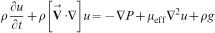
Three-dimensional continuity and the Navier–Stokes equations, shown in equations (1) and (2), in Cartesian coordinates were solved, together with the k–ϵ standard turbulence model


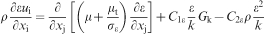
k–ϵ standard turbulence model
The turbulence model is defined as follows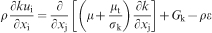
Multiphase model
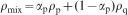
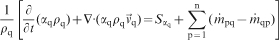
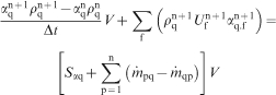
The volume of fluid model was employed to solve the steel–slag–air multiphase system. This scheme performs the calculation of the interface between the phases (p and q) present at each cell based on their fraction as shown16


Modelling conditions
The fluid flow into the billet mould was selected to have Newtonian behaviour without changes in density. Simulations were developed under unsteady state and isothermal conditions. Inlet and outlet were defined as a velocity inlet condition and were calculated by equation (10). Volumetric flows were computed on the basis of the casting speed as shown in Table 1; therefore, the mass balance of steel phase in the simulation domain is achieved
Physical properties of fluids and parameters of simulation
Momentum transfer equations were solved using appropriate boundary conditions, such as no slip condition for all surfaces, a velocity distribution inside the SEN that obeys the 1/7 law17 and a kinetic energy in the SEN tip defined by the velocity distribution. In the viscous sublayer, the high velocity gradients were related with the main flow through the logarithmic law.18
The governing equations were discretised in FLUENT using an implicit, first order upwinding scheme and the SIMPLEC algorithm for pressure–velocity coupling.19 Convergence criterion was obtained when the residuals of the output variables reached values equal or smaller than 1×10⁻⁴. The dimensions of the billet mould are shown in Fig. 1. The computational grids were built in GAMBIT and have 900 000 structured cells as shown in Fig. 2. All simulations were performed in three SUN workstations with two processors at 2·6 GHz and 2 GB RAM memory.
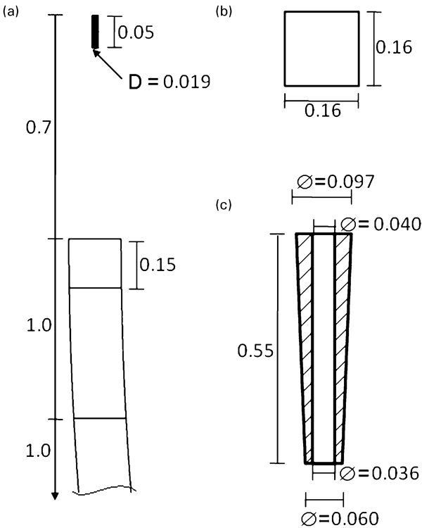
Dimensions of billet mould and SEN (m)
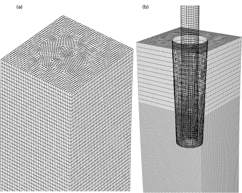
Isometric view of system mesh
Discussion of results
The open stream case was simulated first, considering the steel–air system. This case was employed to study the high intensity oscillations of the liquid steel free surface. This first stage was considered as a start point to understand the importance of using the SEN.
Figure 3 shows the velocity fields for this case corresponding to 120 s of simulation time at the longitudinal symmetric plane of the mould. Recirculation air flows were observed in the upper part of the figure due to the momentum transfer between the falling steel stream and the environmental air. In addition, it is easy to note that the highest velocities are located at the surface centre where the stream impact and the flow patterns are very chaotic inside the upper part of the mould. These variations are linked to the falling steel stream, the turbulence and the entrapped air in the mould that rises as bubbles, as shown in Fig. 4. These variables induce strong unstable changes to flow dynamics of the steel. In addition, Fig. 3 shows a characteristic of open streams, which is the buffer zone; this zone corresponds to the maximum penetration depth of steel stream. The solidifying shell growth process at the meniscus is strongly dependent on bath level disturbances. Consequently, these strong oscillations of the bath surface are undesirable phenomena because they affect directly the solidification mechanisms there.
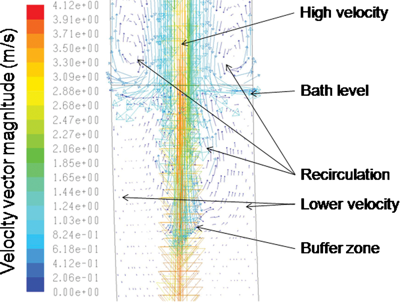
Velocity profiles at symmetric plane in mould for open stream case
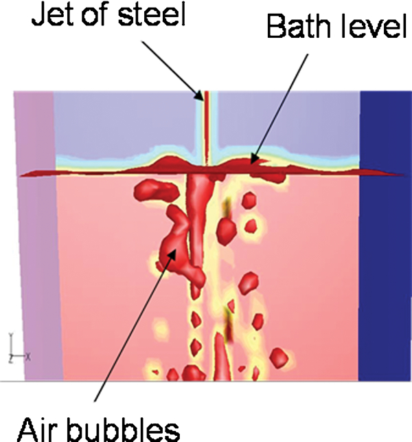
Isometric view of air bubbles and bath level oscillation for open stream case
Figure 5 shows the free surface behaviour at different times. It can be seen that the largest level oscillations are located at the impacted steel stream, and these gradually vanish as the steel goes to the mould walls. It must be noted that the level oscillations are very different for each time, which is due to the inertial forces of the turbulent steel stream together with the random nature of bubbles exiting through the free surface of the steel. This figure illustrates that the oscillations described above are present throughout the continuous casting process as an inherent phenomenon. Hence, casting operation using open stream is not recommended for quality steels.
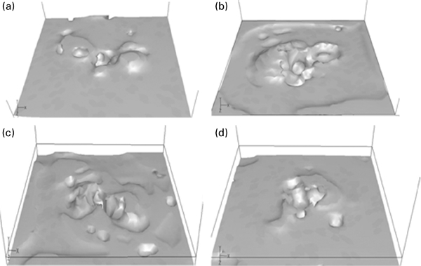
Isometric view of bath level oscillations for open stream case at different simulation times
The second stage of this modelling study was performed with the SEN positioned along the vertical axis of the tundish nozzle. For all the flowing simulations, a simulated domain was set up with an initial phase distribution as shown in Fig. 6. Velocity fields and path lines at the longitudinal symmetric plane of the mould were obtained in order to analyse the flow patterns, as shown in Fig. 7a and b respectively. In these figures, it can be seen that the steel stream from the SEN is not completely centred in relation to both radii of the mould (inner and outer), which results in non-symmetric flow patterns.
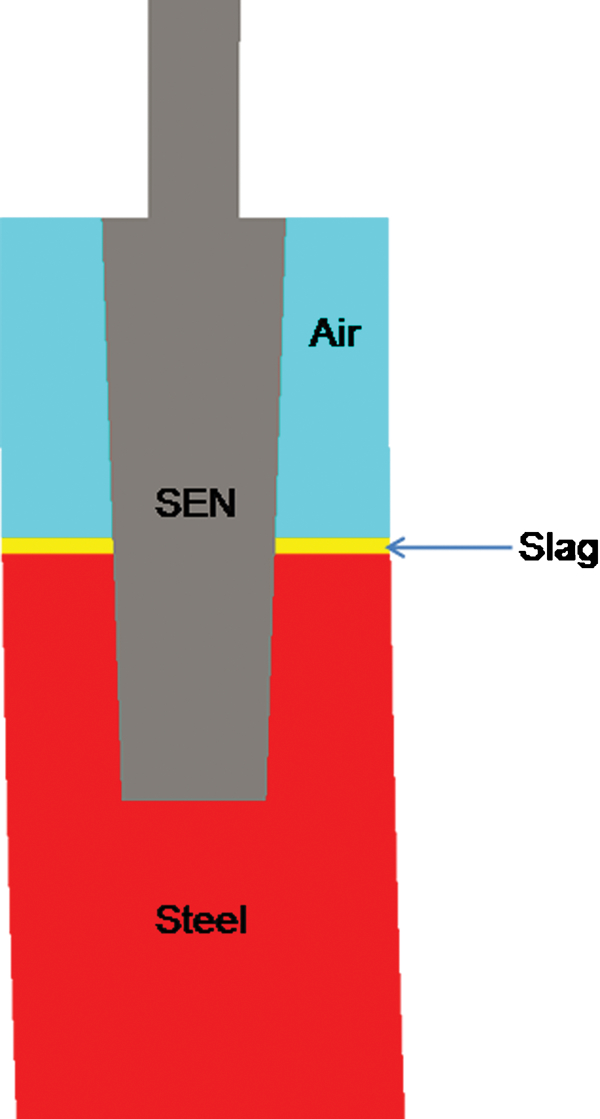
Conditions of initial distribution for simulated phases
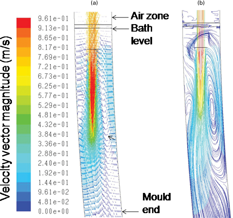
Flow patterns at vertical symmetric plane for aligned and centred SEN case
The mould curvature and the gravitational force induce the steel stream trajectory closer to the outer radius. This produces a major space between the inner radius and the incoming steel stream versus the outer radius and promotes a pronounced recirculating flow, which generates a bigger volume of steel going towards the free surface at that side.
However, the path lines indicate that this ascending flow does not completely reach the free surface because most of this flow changes its trajectory and impacts the SEN tip. Then, it flows around the SEN to continue its ascending trajectory close to the outer mould radius. In consequence, non-symmetric flow patterns in the free surface resulted, as shown in Fig. 8.
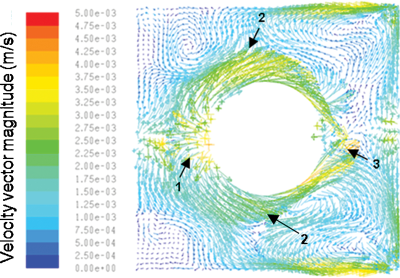
Flow velocity vectors in traversal plane at steel bath level for aligned and centred SEN case
The steel ascending close to the SEN in the outer mould radius (point 1) surrounds the nozzle in both directions and meets in point 3. The flow supplies the free surface close to the inner mould radius flowing in a contrary trajectory, and because of that, two recirculations are formed as indicated by point 2 in the figure. In spite of all these flow pattern variations, the free surface is more stable in comparison with the open stream case, and as a result, the meniscus close to the mould walls remains in almost steady conditions. At this point, it is possible to conclude that SEN usage allows a better control of the turbulence and consequently generates more stable fluid flow patterns into the mould and in the free surface.
It is known that SEN positioning on the centreline of the strand is not always correct for many reasons, and consequently, the SEN may be off centre in the mould or not aligned vertically. Considering the latter, it was decided to simulate four cases with a hypothetical deviation of the SEN axis with respect to vertical of 1 and 2° towards the inner and the outer radius of the mould respectively.
Figure 9 shows the velocity patterns corresponding to 300 s of simulation time at the longitudinal symmetric plane of the mould for the four cases mentioned above. In Fig. 9a and c , it can be seen that a SEN inclination towards the outer mould radius moves the jet considerably closer to the outer radius wall, which promotes an increment of the steel volume that ascends and recirculates at the inner radius, as indicated by the arrow in Fig. 9a . As a result, the fluid flow patterns are non-symmetric for the two cases, and consequently, a fluctuating free surface could be expected. When the SEN has an inclination of 2° to the inner mould radius (Fig. 9b ), the velocity pattern shows that the steel jet moves closer to the inner mould radius and promotes a recirculation flow at the outer radius wall, as is indicated by the arrow in the figure. This is contrary to the flow observed in Fig. 7. However, when the SEN has an inclination of 1° to the inner mould radius (Fig. 9d ), the flow pattern inside the mould is considerably symmetric due to the closer alignment between the SEN and the mould walls. This pattern gives recirculation flows at both sides, but with lower intensity than any of the previous cases, and in consequence, the free surface must be more stable.
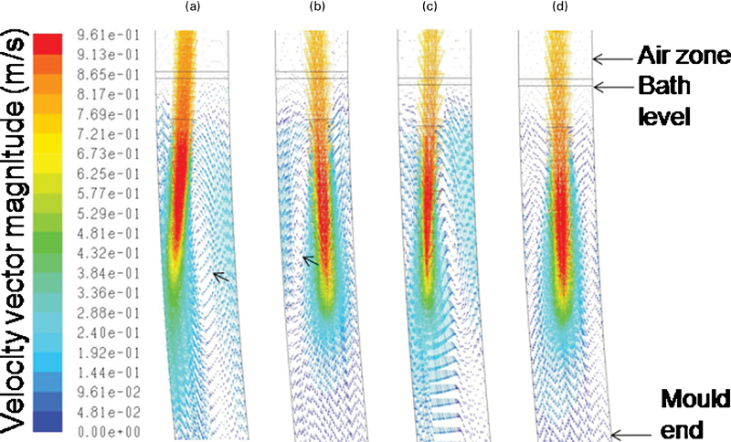
Velocity fields corresponding to 300 s of simulation time at vertical symmetric plane for misaligned SEN cases
To analyse the fluid flow at the free surface, the velocity patterns were obtained numerically and are shown in Fig. 10 for the same conditions and simulation time as that of Fig. 9. It is evident that the flow patterns at the free surface are considerably irregular and non-symmetric for almost all cases as shown in Fig. 10a, b and d , where high velocities and several vortices are indicated by numbers; the exception is the case when the SEN has a 1° inclination towards the inner mould radius (Fig. 10c ). For this case, the velocity patterns are very symmetrical, leading to regular vortices of low intensity as shown by the arrows. Therefore, the steel flow is upward at the corners of the mould, being slightly more intense at the inner radius corners, and descends towards the centre of the wall faces without inducing severe free surface oscillations.
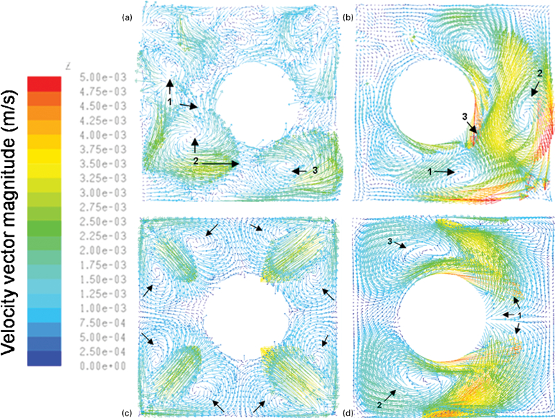
Velocity fields corresponding to 300 s of simulation time in traversal plane at steel bath level for misaligned SEN cases
Figure 11 shows the velocity vector patterns at the parallel plane located 0·055 m from one of the straight mould walls superimposed with the free surface deformation for the same conditions and simulation time as in Fig. 10. It is important to mention that the scale in Fig. 11 was maximised for a better appreciation of the free surface deformation. In Fig. 11b and d , there is a clear relation of the free surface deformation and the velocity vector patterns. The high momentum flows ascending close to the inner mould radius generate a free surface elevation, while the combined effect of low pressure value and shear stresses produces the free surface to go down. Figure 11a shows inverse flow conditions, ascending close to the outer mould radius, which is supplying the free surface. Therefore, the free surface depression is presented on the right side but with lower intensity. Finally, Fig. 11c shows a stable free surface due to the symmetry of the velocity vector patterns. The free surface is supplied uniformly from the four corners as mentioned in Fig. 10c .
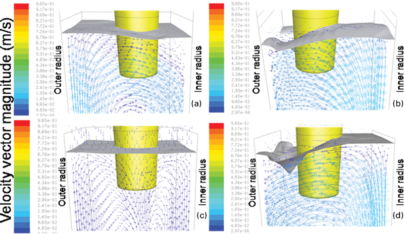
Velocity fields corresponding to 300 s of simulation time with surface deformation in vertical plane located 0·055 m from straight frontal wall for misaligned SEN cases
Knowing the negative effects of the free surface fluctuation on steel quality, it was decided to compute its maximum values for all cases where the SEN is used, and the results are shown in Fig. 12, which indicate clearly that cases with centred SEN as well as those with inclined SEN towards the outer mould radius showed the largest deformation of free surface. On the other hand, the cases where the SEN deviation is towards the inner mould radius showed the lower deformation values. The optimal results were obtained for a SEN deviation of 1° towards the inner mould radius, which showed the lowest oscillations.
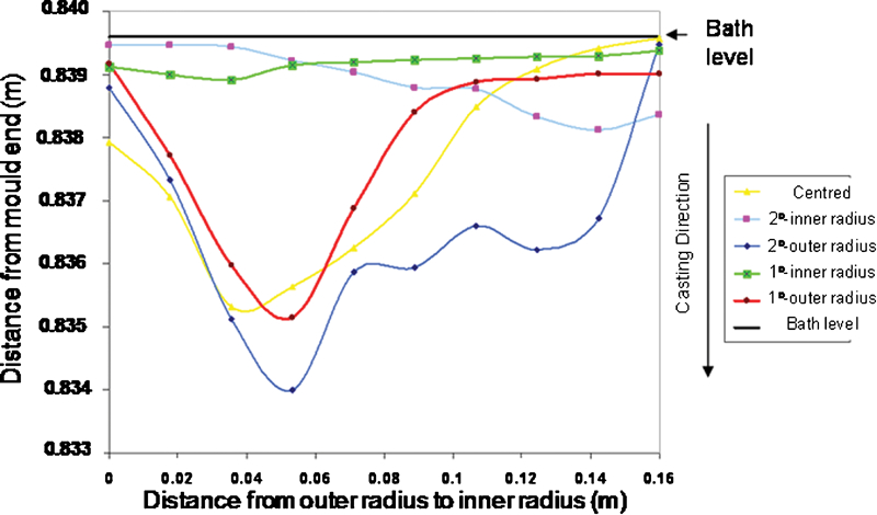
Bath level deformation for cases where SEN is used
Conclusions
The numerical simulation of the liquid steel entry behaviour into a curved billet mould when it is delivered by an open stream and when it is equipped with a SEN allows the following conclusions.
The numerical flow patterns for open stream and using SEN are considerably different, and its application must be selected according to the desired steel quality; however, the results suggest SEN usage.
The use of a SEN decreases considerably the free surface oscillations in comparison with the open stream case, but the flow patterns at the free surface are strongly affected by the SEN inclination.
The use of a centred SEN in a curved billet mould does not assure a symmetric flow into the mould. On the other hand, non-centred SEN generally promotes strong recirculation flows around the steel jet that may affect the flow pattern negatively.
Submerged entry nozzle inclination necessary for optimum steel behaviour into the mould may be changed with the particular caster machine. For this particular study, 1° inclination to the inner mould radius showed the most suitable condition to improve fluid flow patterns.
Footnotes
Acknowledgements
We give thanks to the institutions DGEST, ITM, PROMEP, CONACYT and SNI for their permanent support to the Academic Research Group on Mathematical Simulation of Materials Processing and Fluid Dynamics of the Instituto Tecnológico de Morelia.