
Abstract
Roll forming is one of the important advanced metal forming processes. Simulation is an effective method to study the geometrical and the mechanical character of the strip deformation between the rolls. The spline finite strip method (SFSM) has been developed to simulate the cold forming process. The solution procedures of SFSM are given. The forming processes of four types of sections: electrical resistance welded pipe, channel section, channel section with outer edge and non-symmetrical channel section, were simulated by SFSM. The transverse membrane strain, longitudinal membrane strain and displacement of the deformed strip were obtained.
List of symbols
boundary of outer force on time t
width of the strip
vectors of nodal variables, d = u, v, w, θ, q = i, j

elastic–plastic constitutive matrix

Green strain on time t+Δt
vectors of displacement functions
nodal line number
stiffness matrix in the public coordinates system
stiffness matrix in the local coordinates system
shape functions, i = 1, 2, 3, 4, 5, 6

load vector of body load

load vector of surface load

Kirchhoff stress on time t+Δt
transformation matrix
direction cosine values of x axis, p = x, y, z
direction cosine values of y axis, p = x, y, z
direction cosine values of z axis, p = x, y, z
displacement functions
zone of object configuration on time t
rate of deformation

virtual displacement
vectors of B spline functions, p = u, v, w, θ, q = i, j

Jaumann stress rate of the configuration on time t
incremental displacements
incremental load vector in the public coordinates system
incremental load vector in the local coordinates system
incremental displacement vector in the local coordinates system
incremental displacement vector in the public coordinates system
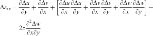
Green strain increments, p = x, y, xy
Introduction
Roll forming is a general term used to describe a large class of continuous manufacturing processes where long strips of sheet metal are deformed into products with desired geometry by passing through a series of rotating rolls arranged in tandem.1 It is one of the important advanced metal forming processes and is used universally for a wide range of products. Since the deformation process is complex, cold roll forming has been developed, to a large extent, on an empirical basis and from experimental knowledge.2 In order to provide better roll design and eliminate some common defects like edge wave, twist and longitudinal curvature, it is necessary to study carefully the geometrical and the mechanical characteristics of the strip deformation between the rolls.
There are several CAD and finite element method (FEM) programs in the literature available for the design of roll formed products, forming rolls and roll pass sequences.3 Kiuchi and his co-workers4 – 6 employed a sinusoidal ‘shape function’ to describe the middle sheet surface between the roll stands. Wen and Pick7 – 9 simulated the forming process of electrical resistance welded (ERW) pipe. Brunet10 developed a specific FE code, PROFIL, to analyse the complete strain history of the material; the design system is based on a combined two- and three-dimensional FEM code. Panton and his co-workers11 examined strain development and analysed the relationship between longitudinal and shear strain during the roll forming process. Senanayake et al. 12 employed computer vision techniques in his method to calculate plastic strains in cold roll forming and demonstrated that most of the guesswork in forming roll design could be eliminated with sufficient knowledge of strains in the workpiece. Nefussi and Gilormini13 proposed a kinematic approach in their paper for predicting the optimal shape and the deformed length of a metal sheet during cold roll forming and then simulated cold roll forming for elastic–plastic materials on a work station. In order to integrate the elastic–plastic constitutive equations, a radial return scheme was employed so that the plastic power rate was calculated.14
Liu et al. 15 employed a finite strip method (FSM) to simulate the roll forming process of the ERW pipe. Alsamhan et al.16 employed FE methods and applied real time remeshing techniques to simulate the cold roll forming process. Lindgren17 investigated cold roll forming of a U channel made of high strength steel. Farzin et al.18 studied determination of buckling limit of strain in cold roll forming by the finite element analysis. Zeng et al.19 presented a new model taking the roll rotation into account. Based on the model, the process of a channel section with outer edge formed with 12 passes was simulated, and the sensitivity analysis of parameters was conducted with an orthogonal design combined FEM model. Tehrani et al.20 utilised finite element simulation to predict local edge buckling as a limiting factor in the cold roll forming of a symmetric channel section. The simulation results show that during the rolling mill set-up phase, the fold angle in the first station should be kept below a particular limit.
Jiang et al.21 simulated the whole cage roll forming process with the explicit elastic–plastic FEM and investigated the strip deformation during the cage roll forming process in detail. Joo et al.22 made efforts to avoid roll forming defects and to optimise forming parameters. FE analysis was performed with high strength steels using commercially available simulation software, COPRARF (TM) and SHAPE-RF (TM). Cavaguti and Ferreira23 performed a numerical analysis of the cold roll forming process using the software MSC SuperForm 2002, where two types of roll forming mills consisting of five stands can be modelled numerically with the same kinetic characteristics of the industrial machine. Mulle et al.24 presented a new method of validating numerically predicted plastic deformation in a cold formed metal strip. Tensile testing of samples of the band’s material was used to obtain a direct link between plastic strain and work hardness of this particular material. Using this correlation, the equivalent plastic strain values predicted by finite element simulations were converted into hardness values.
Hama et al.25 compared the simulation results of the bending deformation of steel sheets using various types of finite element codes. This analysis aims at increasing the accuracy of the forming simulation of high strength steels using the most appropriate numerical strategies. Tehrani et al.26 utilised finite element simulation, making use of the explicit version of ABAQUS 6·4 to predict ‘local edge buckling’ as a limiting factor in cold roll forming of a circular tube section. Han and Lee27 designed the roll forming line for magnesium alloy AZ31B tube; finite element analysis was conducted to determine the design solution and to predict any forming problems. Zhu et al.28 presented a new method of plastic forming profiles: twin symmetry roll axial rolling is described using a spiral bevel gear as a case study. The technology was analysed by producing a three-dimensional model of the spiral bevel gear, and FE analysis was used to simulate the process. Wang and Hua29 established geometrical models of single fixed guide mode and single follow-up guide mode of the vertical hot ring rolling process, then constructed coupled thermal–mechanical finite element models of vertical hot ring rolling and simulated the rolling process of a rectangular section ring.
In this work, the FSM in structural analysis30 is extended and introduced to simulate roll forming process. The analytical model is established to analyse the strain history of roll forming channel sections. The outlines of the simulation method mentioned above are explained in this paper.
Spline finite strip modelling technology of cold roll forming process
B spline finite strip discretisation and solution procedure
In the actual cold roll forming process, the deformed sheet passes progressively through a series of rolls into the final profile with certain cross-sections. Although the entire forming process is very complex, a stage model is developed in the method. The progressive roll stands in roll forming are divided into several stages. The deformed sheet between two progressive roll stands is considered as one stage. The deformed sheet in one stage is the research object in this paper. The research object is divided into i finite strips in the longitudinal direction, and every finite strip is divided into j B splines in the transverse direction. Figure 1 is the finite strip and B spline discretisation model.
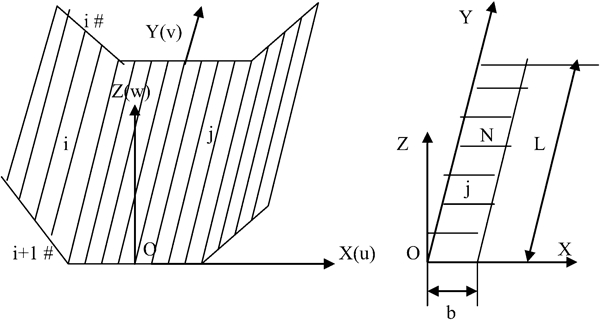
B spline finite strip discretisation model
In this model, when the strip moves out of the rolling mill, the friction is neglected. When the deformed strip between No.i and No.i+1 stand is analysed, considering the constrained function of upper roll and lower roll, this end of the strip is considered as a clamped end, and the other end is considered as a free end. During the roll forming process, the strip deformation between the upper and lower rolls is considered as the result of the upper roll pressing the strip to the lower roll. In every stage, the strip deformation is divided into M displacement increments. The strip deformation in roll forming does not take place over the whole pass, so a contact iteration method is employed to judge the contact area in every displacement increment step. In analysing the strip deformation on time t+Δt, the configuration of the strip on time t is considered as the reference configuration, i.e. the reference configuration is changeable.
In simulation of roll forming, when the deformed strip moves out of No.i roll stand, the strip after spring back is considered as the initial research configuration. The stress state of the strip on this stand is considered as the initial stress state for strip deformation analysis of next roll stand. The information of the strip moving out of No.i roll stand is considered as the initial information for No.i+1 roll stand. Thus, the whole forming process is analysed one stage by one stage continuously, and the analysis data of the deformed strip in every stage are saved.
Displacement functions selection
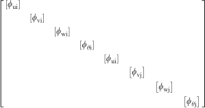
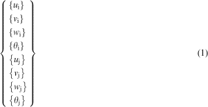
In FSM, the displacement functions consist of two parts: the transverse shape functions and longitudinal functions. In the B spline FSM, the displacement functions consist of two parts: the transverse Hermitian cubic polynomials and the longitudinal B spline function, which satisfies specific boundary conditions of the strip. The distributions of displacements u, v and w for a single strip can be written in forms of the nodal displacement by combining the shape functions. The displacement functions are given in matrix forms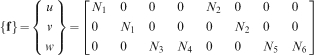
Strain–displacement relations establishment
In B spline FSM, the strip element is employed. Considering the large elastic–plastic deformation in the cold roll forming process, the large deformation strain and displacement relation of plate in incremental form are modified as follows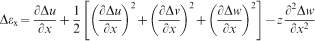

Elastic–plastic constitutive equation establishment
The deformed strip is assumed to follow the Prandtl–Reuss flow theory and von Mises yield criteria; the elastic–plastic constitutive relation is given by
Equilibrium equation establishment and solving
In the updated Lagrangian method, the configuration on time i is considered as reference configuration. According to the virtual work principle, the virtual work equation on time t+Δt is shown as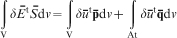
Coordinates transformation matrix modification
The stiffness matrix of a single strip is derived in the local coordinates system. The building and solving of the equilibrium equation for all the strips should be completed in the public coordinates system. Therefore, the strip element stiffness matrix in the local coordinates system must be transformed into ones in the public coordinates system for assembly. Figure 2 is the local and the public coordinates system.
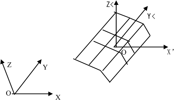
Local and public coordinates system
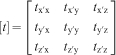
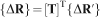
In FSM structural analysis for a single strip, the coordinates in the z direction in both ends of the strip are the same, so the strip element rotation effect cannot be taken into account. In the present numerical method, the strip element rotation is considered. With reference to Fig. 2, the nodal coordinates of all strip elements on time t can be obtained, and the direction cosine values of all strip elements can also be obtained. The coordinate transformation matrix [


Numerical examples and results analysis
Strain analysis for ERW pipe
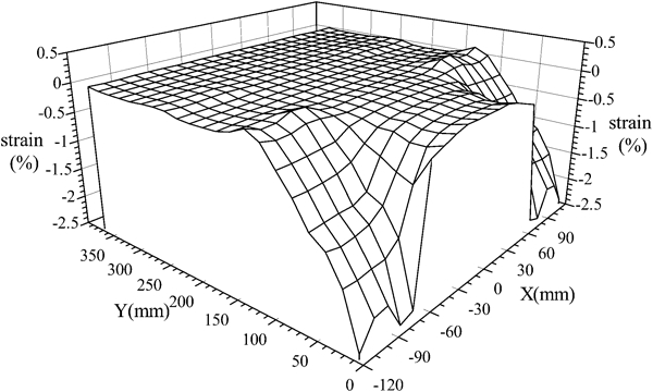
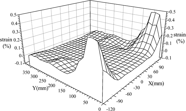
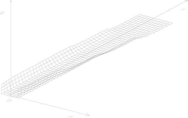
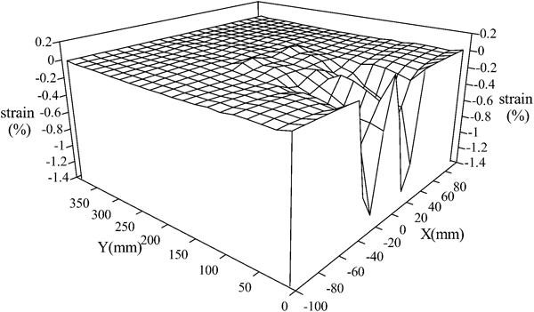
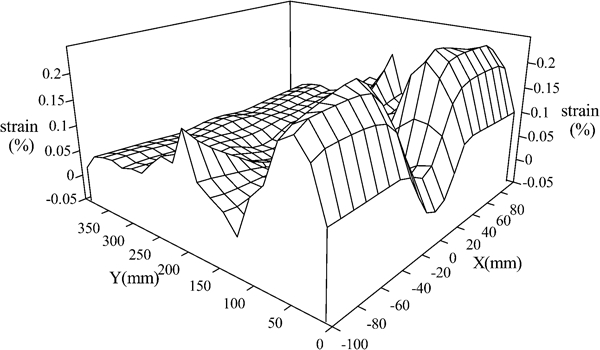
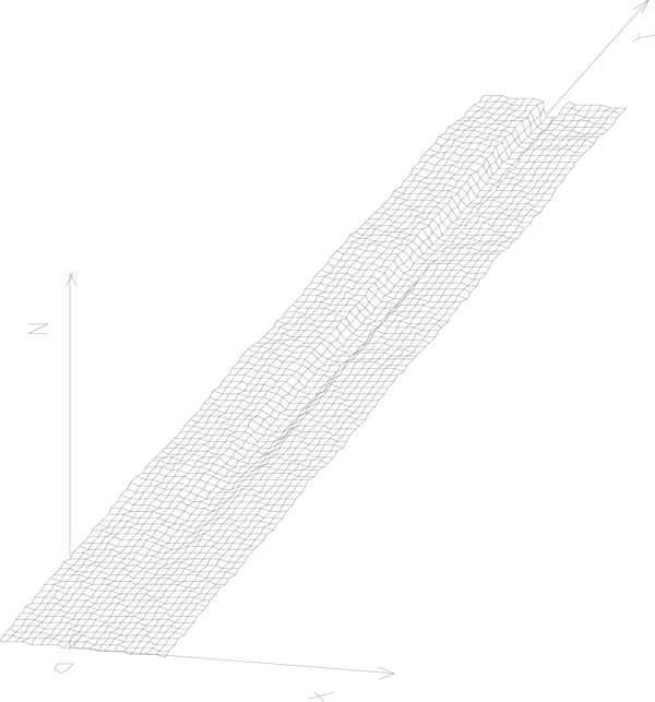
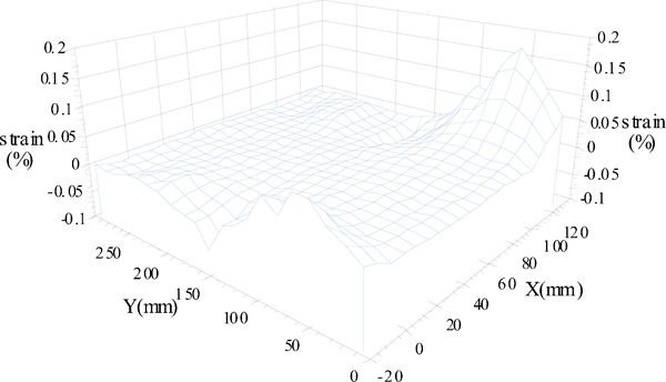
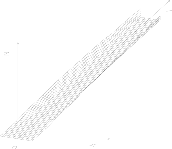
For ERW pipe, the theoretical model above was employed to simulate its forming process. The calculation conditions are shown in Table 1. Figures 3 and 4 are the distribution of transversal and longitudinal membrane strain respectively. X is the distance along the strip width direction, and Y is the distance along the rolling direction. Figure 5 is the total space surface of ERW pipe forming.
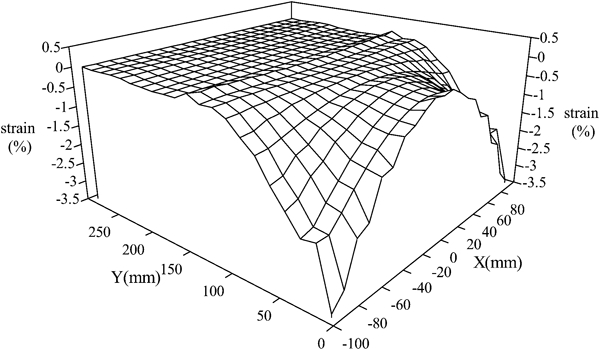
Three-dimensional transverse membrane strain of ERW pipe at first pass
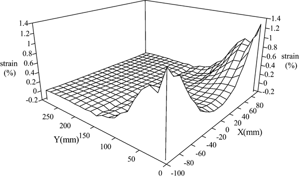
Three-dimensional longitudinal membrane strain of ERW pipe at first pass
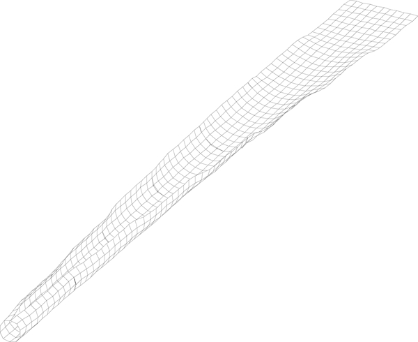
Total space surface of ERW pipe forming
Calculation conditions of ERW pipe forming
For the distribution of transverse membrane strain, it almost equals to zero in the middle part of the forming strip. There is peak value of pressing strain at the edge part of the forming strip, and the pressing strain increases gradually along the rolling direction. For the distribution of longitudinal membrane strain, the pressing strain of the forming strip at the edge part increases gradually along the rolling direction and then decreases. In the middle part, the strain of the forming strip changes from small stretching to pressing strain, and then to stretching strain. The peak value of stretching strain exists at the edge part of the forming strip.
The edge part of the forming strip is the main deformation zone in the ERW forming process. The peak value of transversal membrane strain and longitudinal membrane strain exists all at the edge part of the forming strip. The stretching strain at the edge part of the forming strip is one of the important factors affecting the welding quality of the pipe; a large stretching strain is detrimental for the welding process.
Strain analysis for channel section
For a channel section, the theoretical model above was employed to simulate its forming process. The calculation conditions are shown in Table 2. Figures 6 and 7 are the distribution of transversal and longitudinal membrane strain respectively. Figure 8 is the total space surface of channel section forming.
Three-dimensional transverse membrane strain of channel section at first pass
Three-dimensional longitudinal membrane strain of channel section at first pass
Total space surface of channel section forming
Calculation conditions of channel section
For the distribution of membrane strain, there is the maximum of transverse pressing strain on the leg and the corner part of the channel section, and there is a small change in the web. The transverse strain is very small in the web. The maximum of the longitudinal stretching strain is on the leg and the corner part of channel section, and there is also a small change in the web. The longitudinal strain is very small in the web.
For the total forming process of the channel section, it can be analysed that the leg and the corner part are large deformation areas, and the principal deformation is transverse; the longitudinal deformation is small. Therefore, when designing the roll pass for channel section, it is important to analyse the reasonable distribution of transverse deformation to yield good products.
Strain analysis for channel section with outer edge
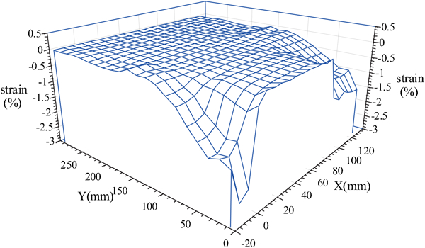
The theoretical model has been used to simulate the roll forming process of a channel section with an outer edge. The calculation conditions are shown in the Table 3. Figures 9 and 10 are the distributions of transverse and longitudinal membrane strain respectively. X is the distance along the strip width direction, and Y is the distance along the rolling direction. Figure 11 is the total space surface of the deformed strip forming.
Three-dimensional transverse membrane strain of channel section with outer edge at first pass
Three-dimensional longitudinal membrane strain of channel section with outer edge at first pass
Total space surface of channel section with outer edge forming
Calculation conditions of channel section with outer edge
The distribution of transverse membrane strain changes very little on the web. The peak pressing strains on the two corner parts of the deformed strip change slowly and are almost the same. The strains on the outer edge part of the deformed strip change little and are almost equal zero. For the distribution of longitudinal membrane strain, it increases gradually from pass no. 1 to 5. The peak stretching strains are on the outer edge part of the deformed strip in front of the roll position. The peak pressing strains are on the web of the deformed strip in front of the roll position. The longitudinal membrane strains are very small on the web.
For the total forming process of the deformed strip, it can be analysed that the outer edge and the corner part of the deformed strip are the large deformation parts. The transverse deformation is principal, and the longitudinal deformation is small.
Strain analysis for non-symmetrical channel section
For the non-symmetrical channel section, the theoretical model above was employed to simulate its forming process. The calculation conditions are shown in Table 4. Figures 12 and 13 are the distribution of transverse and longitudinal membrane strain respectively. Figure 14 is the total space surface of non-symmetrical channel section forming.
Three-dimensional transverse membrane strain non-symmetrical channel section at first pass
Three-dimensional longitudinal membrane strain non-symmetrical channel section at first pass
Total space surface of non-symmetrical channel section forming
Calculation conditions of non-symmetrical channel section
For the distribution of membrane strain, there is a maximum of transverse pressing strain on the leg of non-symmetrical channel section, and there is small change in the web. The transverse strain is very small in the web. The maximum of longitudinal stretching strain is on the leg part of the non-symmetrical channel section in front of rolls, and there is also a small change in the web. The longitudinal strain is very small in the web.
For the total forming process of a non-symmetrical channel section, it can be analysed that the leg and the corner parts are the large deformation areas, and the transverse deformation is principal; the longitudinal deformation is small. For the non-symmetry of the analysed channel section, the deformation angle in the short edge must be larger than that in the long edge on the same pass to prevent the distortion of the section of the product. The rule can be seen from the distribution of the stress and the strain. Thus, when designing the roll pass of non-symmetrical section steel, it is important to consider the non-symmetry of the product to avoid the distortion of a section of the product to yield good products.
Conclusions
This paper has introduced elastic–plastic non-linear spline FSM based on the updated Lagrangian method to cold roll forming field, this theoretical model can be used to analyse the forming process of ERW pipe, channel section, channel section with outer edge and non-symmetrical section steel and to obtain a lot of valuable information to guide the production. The C software of this model can be used to analyse the forming process of other open section steel, and it has provided that this model is a simple and efficient numerical method to analyse the forming process of cold roll forming section steel.
Footnotes
Acknowledgements
The authors wish to acknowledge the financial support by the National High Technology Research and Development Program of China (863 Program) (grant no. 2002AA331180), Trans-Century Training Program Foundation for the Talents by Chinese Ministry of Education.