
Abstract
This study concerns the chemical reactions involved and the phases formed during penetration of slags of variable compositions into porous tundish disposable lining material. The liner is mainly composed of a mixture of MgO and olivine with an organic binder. Slags of different compositions were formulated and indicated a variable composition of CaO (12–20%), SiO2 (44–55%), Al2O3 (4–16%), MgO (10–20%), MnO (9–12%) and FeO (2–3%). Experimental work indicated that when slag penetrated into pores of the refractory, the porosity was reduced depending on the penetration depth. It was observed that the lower the melting point of the slag, the higher the depth of slag penetration by capillary action. The phases of forsterite (Mg2SiO4), magnesiowustite (MgO.FeO) and monticellite (CaO.MgO.SiO2) were formed in the bulk refractory by the slag, and the chief component of the refractory responsible for the formation of those phases is the periclase.
Introduction
In the continuous casting process of steel, the tundish acts as a buffer vessel between steel ladle and the mould. The tundish is often lined with a disposable layer composed of basic materials such as periclase and olivine.
The processes followed in continuous casting of steel significantly affect the quality of final product. In the tundish, the slag plays a key role in metallurgical efficiency; it not only guarantees the steel quality and cleanliness, but is also consistent in performance. The tundish provides thermal insulation by reducing heat loss, prevents reoxidation of molten steel by isolating molten steel from air, and possesses a high capacity to absorb different types of non-metallic inclusions in steel. The selection/modification of slag/flux, therefore, has a considerable impact on the control of slag composition and formation.
Experience shows that a disposable tundish liner is worn most along the slag line during steel casting, which is mainly because of a combined effect of corrosion and erosion.1 Lee and Zhang2 reported about rounding of the refractory grains due to diffusion during corrosion. Our earlier studies suggest that the corrosion of the MgO based refractory in siliceous slag is mostly diffusion controlled.3 Mass transfer takes place because of a concentration gradient, as predicted by the equation
During casting, the equilibrium near the slag/refractory interface is disturbed due to continuous turbulence. In order to maintain the equilibrium, MgO from the refractory diffuses into the slag. Further, the CaO/SiO2 ratio in the case of MnSi killed tundish slags varies between a basicity of 0·5 and 1. According to the studies carried out by Turkdogan,4 solubility of MgO in the CaO–MgO–FeO–SiO2 system at operating temperature is greatest in the above basicity range. Hence, it can be concluded that the tundish slag has a deficit of MgO at the steel making temperature. An addition of lime, dolomite and bauxite is a common practice to increase the fluidity of the slag and its basicity, causing a reduction in the saturation level of MgO, which comes from the refractory.2, 5 In order to reduce slag additives, a calcium–aluminate based flux with CaO, Al2O3 and MgO as its major components (Table 1) is often used as a replacement. The flux achieves rapid slag formation due to its low melting point (<1325°C). In addition to the low melting point of the calcium–aluminate phase, a higher magnesia content of this flux contributes to optimise the life of the refractory lining during the initial stages of secondary steelmaking process when corrosion is at its peak. It is therefore, essential to have a thorough understanding about the interaction mechanisms of these components present in the slag with the disposable tundish liner and the impact slag has on liner performance.
Chemical compositions of plant slag and other slag modifiers/wt-%
Hence, in the present study, efforts have been made to understand the combined effect of MgO, CaO and Al2O3 content in slag on diffusion of MgO from the refractory. The effect of slag compositions by adding various additives to the tundish slag has been studied.
Materials and methods
The tundish slag of MnSi killed steels was considered as the standard slag (P) in this study. Test slags were prepared by adding a specific calcium–aluminate (CaO.Al2O3) based LDSF flux, calcined magnesia (MgO) and calcined lime (CaO) to the slag P in the amount shown in Table 2. Typical chemical analysis of slag P and additives are shown in Table 1. It is desirable to obtain a tundish slag with low fluidity so that its penetration can be minimised. Furthermore, it is also desirable to generate a slag having a melting temperature in the range of <1350°C, thereby facilitating inclusion removal. Hence, before batch formulation, the effect of MgO concentration on the melting point of the slag P was determined using FactSage6 to design the slag chemistry for this research. FactSage is used to generate thermodynamic data of inorganic substances from experimental information. As shown in Fig. 1, the melting temperature decreased initially up to 10%MgO, then increased with increasing content. The added MgO might have acted as a network modifier, forming low melting monticelite CaO.MgO.SiO2 (CMS) that led to a decrease in melting temperature. On increasing the MgO content beyond 10%, the C/S ratio was increased, thereby gradually increasing the melting temperature of the slags.7 Higher MgO content in the slag may also have facilitated the formation of forsterite, which has a high melting temperature. Based on the above findings, the MgO content was restricted to 20 wt-% in the final slag formulations for the present study.
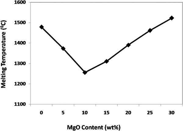
Variation in melting temperatures as function of MgO content in wt-% (as obtained from FactSage)
Formulation of different test slags along with their denotations/%
Design of experiment and slag preparation
In order to obtain test slags, a series of experiments was designed by making the additives in different ratios to the slag P. Details of the batch formulation and their respective denotations are summarised in Table 2. The concentration of MgO was varied from 10 to 20% (Table 3). The components were mixed in a mortar pestle thoroughly and the mixtures were melted in a platinum crucible at 1550°C in Ar atmosphere using a muffle furnace. After water quenching, the test slags were ground and used in cup tests. The chemical analysis of each batch of slag is summarised in Table 3. FactSage software was used to calculate the melting temperature of the prepared slags and the pressure considered for the calculations was 0·0001 atm. The actual melting temperature was measured by sessile drop testing under Ar atmosphere as per the details mentioned elsewhere.8 Sintered dry vibratable material (DVM) was used as substrates for the sessile drop study. In practice, the top surface the tundish slag is exposed to atmosphere while the refractory coming in contact with the slag layer below it as well as the slag penetrated layer are devoid of free oxygen. Hence, a reducing atmosphere was considered for both FactSage and sessile drop studies.
Composition of test slags melted at 1550°C followed by quenching/wt-%
Refractory cube preparation
A commercially available DVM based on dead burnt magnesia (DBM) and forsteritic olivine [(MgFe)2SiO4] in the ratio of 40∶60 was used for the present study, and has a chemical composition given in Table 4. Test samples of DVM were prepared by taking the dry mix in moulds of 75×75×75 mm3 in size and vibrating for 10 s at a frequency of 50 Hz. The blocks were initially heated at 250°C for 2 h to obtain handling strength, than test crucibles were prepared by drilling a hole of 25 mm diameter×25 mm deep in the 75 mm cubes.
Chemical composition of DVM used in experiment/wt-%
Cup test
The penetration behaviour of different slags and their interaction with the refractory was studied using a static crucible corrosion test at a temperature of 1450°C with a 24 h soaking. In order to simulate the plant condition, the corrosion test was done in air atmosphere, where the top surface of the slag is in contact with air. The crucibles were cut exactly half after the slag test to measure the penetration depth. The deep black coloured portions in all three directions on the cut face of the crucibles were measured for each case and averaged out to obtain the penetration depth value (Fig. 2).
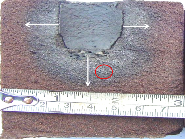
Typical crucible showing extent of slag penetration in different directions
Chemical analyses of the slag and DVM samples were determined by inductively coupled plasma (ICP, Model No–ARCOS-165). Powders of size <60 mesh were used for the analysis.
The effect of slag interaction with DVM material on the fraction of different phases formed at 1450°C was analysed using Quantitative Evaluation of Minerals software on a scanning electron microscopy (QEMSCAN) instrument (model no. E430). QEMSCAN uses electron beam technology combined with high resolution back scattered electron (BSE) and secondary electron (SE) imaging having up to four light element EDS (energy dispersive spectrometers), and a microanalyser to analyse minerals. During QEMSCAN analysis, a detailed database of statistically representative mineral particle information is built up, which are later used for analysis. It is a powerful automated system that can acquire and process vast amounts of chemical and surface data. The samples were prepared from the position circled in Fig. 2 for all the cubes.
Results and discussion
Melting point
Figure 3 shows the melting points of different slag formulations calculated using FactSage. As observed, solid phases such as olivine [(MgFe)2SiO4], silica (SiO2), calcium–alumino–silicate (CaAl2Si2O8), calcium–magnesium–silicate (CaMgSi2O6, Ca2MgSi2O7) coexisted along with the slag at lower temperatures. However, their quantity decreased as the temperature increased. The temperature beyond which only slag existed has been considered as the melting point of the present slag formulations.
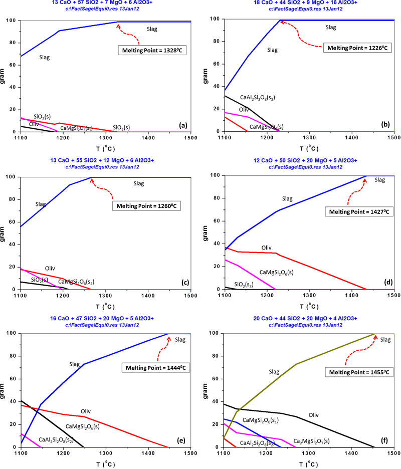
Melting point of slag formulations calculated using FactSage
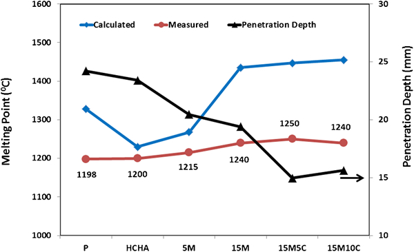
Figure 4 summarises the calculated melting point and measured melting point values along with slag penetration depth measurements. The melting point of slag P was measured to be 1198°C. Slag HCHA was found to have the lowest melting point (1200°C) of the slag mixtures. Higher amount of CaO, Al2O3 in the flux (Table 1) is believed to have moved to the low melting temperature region surrounded by 2CaO.Al2O3.SiO2 (C2AS), CaO–SiO2 (CS) and CaO.2Al2O3.SiO2 (CA2S) having an eutectic at 1300°C in CaO–Al2O3–SiO2 ternary system. The addition of 5 wt-%MgO to the slag P caused the melting point lower down to 1215°C, probably due to formation of CaO–MgO–SiO2 based low melting phases, thus MgO acted as a modifier. However, an increasing trend was observed with the increase in MgO content to 15 wt-%. With the addition of CaO to the slag formulation, labelled as 15M5C, the melting point further increased due to presence of two high melting phases. A slight decrease in the melting point was observed in case the of slag formulation 15M10C. It was noted in Fig. 4 that the slags HCHA and 5M had a melting temperature value close to the calculated melting point value; however, some differences were observed for the other slags. It can be inferred that MgO behaved as a network modifier in compositions having <10%MgO, while it contributes to an increase in the slag melting point at >10%MgO, probably by forming forsterite (2MgO–SiO2) in the slag. In addition, behaviour of a single constituent in a multicomponent slag is different in different circumstances due to its interaction with other constituents, thereby affecting the melting behaviour of the slag to a great extent. Hence, these differences between the measured and calculated melting temperatures results were expected. However, the difference of ∼200°C between these two temperatures for the slags 15M, 15M5C and 15M10C is not clearly understood and requires further investigations. Therefore, the melting temperatures obtained using FactSage should not be considered accurate, rather should be considered as a relatively good indication that gives an insight of the melting point.
Change in melting point and penetration depth for different slag compositions
Slag penetration depth
From Fig. 4, it is evident that the slag penetration depth into the DVM block during cup test was mainly governed by the melting point of the slags, as the melting point temperature increased, the slag penetration decreased. Slag compositions P and HCHA having the lowest measured melting points were found to have the greatest penetration. As expected, the penetration depth decreased with an increase in the melting point of the slag compositions. It has been reported that slag melting temperature has a large effect on the penetration depth through its effect on viscosity.9 The mechanism of initial slag penetration into the refractory when it first comes in contact with the hot liquid is thought to be by capillary action. As temperature decreases away from the hot face, the slag viscosity increases, causing penetration depth to decrease.
QEMSCAN study
Mineral phase changes and their relative quantities after cup testing for all the slag formulations are illustrated in Fig. 5 and Table 5 respectively. Figure 5a depicts QEMSCAN image of the pure DVM sample after heat treatment at 1450°C. The mineral concentration data confirm that the sample consisted of ∼57%Mg–Si–O, 8%Mg–Fe–O, 11% periclase and 21% porosity.
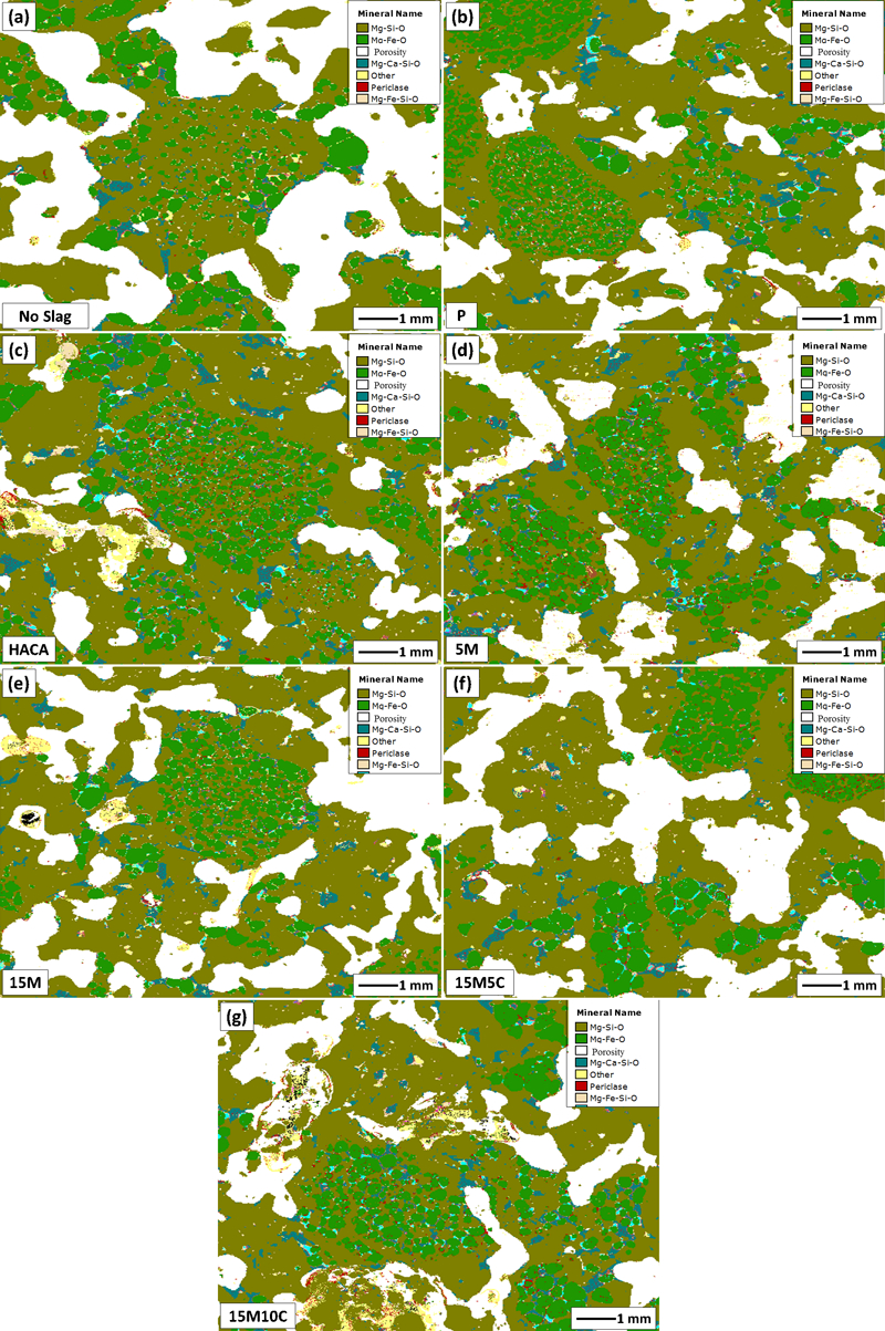
QEMScan analysis of DVM blocks before and after cup test with different slags
Change in mineral phases before and after cup test with different slags (%) obtained from QEMSCAN
However, for the samples after cup tests, the major changes could be observed in terms of porosity, magnesiowustite (Mg–Fe–O) and periclase phases, along with small variations in forsterite (Mg–Si–O) phase. Porosity of the slag treated samples was reduced from 21% to up to 6% in P and HCHA and up to 17% in 15M5C (Table 5) depending on slag penetration depth (Fig. 4). Higher amount of forsterite formation after treated with slag P can be attributed to the presence of higher amount of SiO2 component in the slag. Samples treated with HCHA slag was found to have a porosity of only 6% compared to approximately 16–19% in case of 15M, 15M5C and 15M10C treated samples. The change in porosity showed similar trends to the penetration depth data in Fig. 4. Moreover, an increase in Mg–Fe–O content from 8% in pure DVM sample up to ∼22% in the slag treated one is evident from the table. Formation of magnesiowustite is mainly governed by the diffusion of FeO present in olivine into adjacent periclase grains at high temperature. The FeO content of the slags formulated for the present study varied between 2·5 and 3 wt-%. Higher wustite content in the slag treated samples compared to original DVM is indicative of diffusion of FeO from slag in addition to FeO diffusion from olivine grains. Further, forsterite is a desired phase as it is refractory in nature. Higher forsterite content in case of DVMs treated with slags P, HCHA and 5M can be attributed to higher penetration depth, whereas, that in the case of slags 15M, 15M5C and 15M10C is probably due to the higher MgO content in the slag compared to other compositions which is the probable reason for lowest slag penetration in these samples. Mg–Ca–Si–O also varied slightly, from 3 to 6%. With a higher addition of CaO in slags HCHA, 15M5C and 15M10C, the formation of this phase was higher.
During cup testing, the slag penetrated into the pores of DVM cubes by capillary action. Once penetrated, the refractory surface area coming in contact with slag became available for slag interaction. The higher the slag penetration, the greater was the refractory surface coming in contact with penetrated slag. The periclase grains in the DVM cube is believed to have reacted with various components of the slag, thereby forming phases like wustite, forsterite, monticellite, etc., ultimately leading to a decrease in periclase content in the refractory. Presence of wustite phase in the slag penetrated portion of the refractory is indicative of an environment similar to the plant condition. Here, although the top surface of the slag was in contact with air, the layer below it and the penetrated portion of the refractory was still in a reducing atmosphere. Higher contents of wustite could be observed in samples treated with slag formulations having lower melting temperatures and higher penetration, such as HCHA and 5M. Because Fe+2 is a fast moving ion, reaction of this component present in slag with the periclase grains is expected to have led to the higher initial wustite phase formation. When the slag refractory system reached a local equilibrium, the SiO2 of the slag reacted with the available MgO of the DVM to from forsterite, thus depleting the MgO concentration, which made the slag basicity ≤1. This basicity leads to the formation of montecellite. As the availability of periclase was negligible, changes in forsterite after the cup test was minimal versus the change in wustite and porosity. Higher Mg–Ca–Si–O phase content in the cases of samples treated with HCHA, 15M, 15M5C and 15M10C slags can be attributed to the higher amounts of CaO and MgO (20%) in these slags.
In the case of a static cup test, very little/no corrosion of the refractory grains could be observed. In practice, however, the extent of corrosion is higher owing to mass transfer phenomena due to slag penetration and chemical reaction.1 This mass transfer is further governed by turbulent flow parameters. The greater the turbulence, the higher is the corrosion and erosion of the refractory lining.
Conclusions
The present study indicated that the MgO content in the slag had an influence on its melting temperature, and ultimately in its penetration behaviour. Penetration in periclase–olivine based refractory by calcium silicate slags at 1450°C in a static test indicates that capillaries, such as open pores, are the main channels of initial slag penetration. Development of different phases such as Mg2SiO4, MgO.FeO and CaO.MgO.SiO2 after cup test is attributed to the interdiffusion of various ions between the refractory grains and slag. Flow of liquid has a major effect on degradation of the refractory lining. Increased and turbulent flow can both accelerate chemical interactions and cause mechanical wear. Hence, further studies on slag–refractory interaction under dynamic conditions are required to understand the actual reaction mechanism that would help in adjusting a proper slag formulation for tundish applications.
Footnotes
Acknowledgements
The authors wish to thank Dr Tamal K Ghosh for the microstructural studies using QEMSCAN instrument and Mr Chenna Rao for the FactSage analysis.