
Abstract
Flue gas recirculation (FGR) has been incorporated into the sintering process with the aim of improving productivity while fulfilling tightened environmental regulations. The incorporation of FGR inevitably requires changes in the process equipment as well as incoming and outgoing gas conditions such as temperature, composition and flowrate. These changes may affect not only the reactions in the bed but also the factors related to the design and operation of the plant, which requires the checking of possible effects on gas conditions over the entire bed. The modelling approach proposed in this study for a sintering bed uses a flowsheet process simulator as the starting point for studying the effects of FGR on the sintering process. This paper is the first of two which will present comprehensive information on the modelling approach, and details of the modelling cases and the corresponding results will be described in the companion paper.
Introduction
Sintering is a thermal treatment process for the agglomeration and densification of fine particles to form larger particles. In the iron and steel manufacturing process, sintering is used to process fine particles of iron ore, together with other constituents, as feed material for a blast furnace. As issues of productivity, quality control, energy efficiency and environmental impact become more important, the technique of flue gas recirculation (FGR) has been applied to the sintering process to increase production while at the same time controlling waste gas and pollutants. However, implementing FGR inevitably brings changes to gas flow and conditions across the bed, which is hugely influential on the reactions in the bed as well as on the entire system. Moreover, the degree of change may differ depending on the process configurations, i.e. the selection of the locations for flue gas extraction and supply as well as the recirculation ratio.
Given the fact that gas conditions play a significant role in the sintering process and can be strongly related to the process design or operation, the effect of a change in plant configuration or operating conditions on the gas flows in and out of the bed needs to be investigated. The purpose of this study is to propose a modelling approach for a sintering bed related to the application of FGR. A commercial flowsheet process simulator is employed, with a special focus on the conditions of incoming and outgoing gas flows across the solid sintering bed. This paper is the first of two papers and presents comprehensive information on the modelling approach with the background of process modelling of a sintering bed for FGR. Details of the modelling cases and the corresponding results are minimised and will be described in the companion paper. 1
Previous studies of sintering process fundamentals
Fundamental reactions in sintering bed
As feed material for the sintering process, fine ore particles are mixed with fuel coke, limestone and water in a granulator to form pseudoparticles. The fuel mixture is then fed onto the travelling grate, ignited from the top surface and experiences a series of sintering reactions such as coke combustion and partial melting and solidification of particles. While solid materials are slowly transported down the bed, air or oxidant gas flows across the packed solid layer from the top to the bottom of the bed due to down draft suction fans. The sintering process terminates when the combustion zone reaches the bottom of the bed. Coke combustion in the bed is accompanied by ore melting, heat transfer between solid and gaseous materials, moisture condensation and drying, and other chemical reactions. Combustion gas is exhausted from the bottom of the bed and flows down through wind boxes and ducts which are connected to flue gas cleaning equipment, and is ultimately discharged through a stack.
A cross-sectional conceptual diagram of a typical sintering bed is shown in Fig. 1. 2–4 Generally, sintering bed layers can be characterised as the sintered zone, the combustion zone and the raw mixture zone, according to the state of the solid materials. The sintered zone is a layer of materials including burned coke and other solid materials which experienced high temperatures during coke combustion. Heat transfer occurs between the sintered hot material and the inlet gas, and so the sintered ore cools down while the inlet gas is heated. In the combustion zone layer, coke combustion and ore melting take place. The combustion zone can be distinguished as the area where solid coke temperature is >1000 K. 3,4 The lowest layer is the raw mixture zone where drying and condensation take place. The computational models are mostly concerned with the reactions of sintered ore cooling and inlet gas heating, coke combustion, the thermal and chemical reactions of solid materials, and moisture evaporation and condensation.
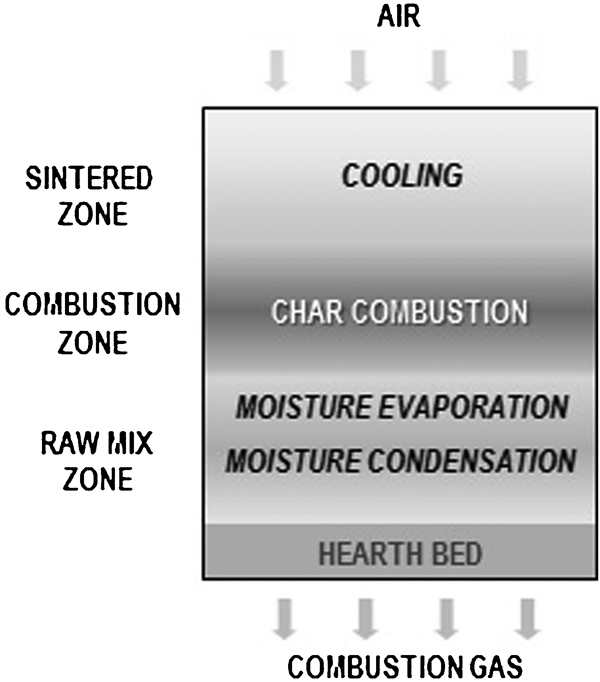
Cross-sectional diagram of sinter bed for model
Sintering bed models in previous research
Various studies on the sintering process have hitherto been made for a wide range of purposes. Previously reported mathematical models for sintering beds described overall sintering phenomena along with physicochemical processes and detailed situations in the bed to investigate the effect of major factors on the sintering process. Muchi and Higuchi 5 created a mathematical model for the sintering process to see the effects of operating variables such as gas conditions in the ignition furnace, ignition time, feed particle diameter and temperature, coke content and voidage of the bed. Toda and Kato 6 created a model to consider drying and condensation, coke combustion, limestone decomposition, ore melting and solidification, and FeO formation and reoxidation to see the effects of operating factors such as coke size, preheating of raw mixture, airflow distribution and heat pattern in the sinter layers. Shibata 7 also conducted a study with a mathematical model. He investigated factors which could affect sintering performance, including blend ratio of coke and limestone, moisture content in raw mixture, melting properties of raw materials and conditions of ignition. Other mathematical models focused on specific topics such as moisture drying and condensation, gas flows and bed permeability, 8–10 and different input gas conditions. 11,12
Conceptual expressions of mathematical models and examples of available results presented by Yang et al. 2–4 are shown in Figs. 2 and 3. The authors investigated the effects of operating factors such as coke and water content, particle diameters, air suction rate, and ignition time and temperature using numerical model for solid fuel combustion. For the study, a three-dimensional bed was simplified into an unsteady one-dimensional model represented by a set of vertically configured segments as shown in Fig. 2. The approach had similarly been applied for previous solid fuel bed combustion modelling in travelling grate type combustors. 13 Heat and mass transfer and the physical properties and chemical reaction rates for solid and gas phases were calculated for each of the discretised segments at the given time step. The time steps could be considered as the directional and locational progress of sintering reactions in the bed, and so the results were spread horizontally to show the situation in the bed graphically, as shown in Fig. 3a , together with the results for specific factors, as shown in Fig. 3b and c .
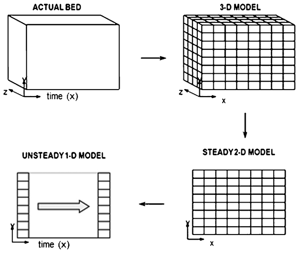
Conceptual expressions of bed models
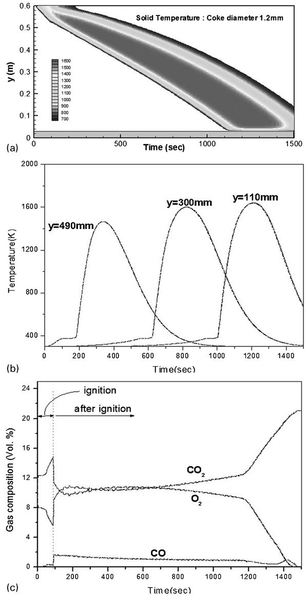
a solid temperatures in the bed (combustion zone temp. changes for different conditions); b solid temperature profiles of three different points in the bed; c flue gas composition at the bottom end of the bed
Sintering process with FGR
Flue gas recirculation and changes in gas conditions
The main issues of sintering in the steelmaking industry are related to productivity, quality control, energy consumption or plant efficiency, and environmental regulations. As one of the measures to cope with the changing operational environment, FGR is incorporated into the sintering process to give an environmentally friendly production increase. The conventional sintering process, which uses ambient air as the input gas, and the FGR process can be easily distinguished. Using the schematic diagrams in Fig. 4a and b respectively, it is seen that the FGR process needs additional gas flow lines, gas supply hoods, and equipment for recirculation or input gas control. The main purposes and effects of FGR can be summarised as follows. By applying FGR, it is possible to reduce the amount of exhaust gas vented through a stack, thus reducing the size and capacity of exhaust gas treatment facilities, which can help minimise the capital cost of pollutant treatment systems which have to cope with current or future environmental regulations. Furthermore, efficiencies of the gas treatment facilities can be improved when the concentration of pollutants in the waste gas is higher due to recirculation. Energy savings can also be expected due to the utilisation of the sensible heat of the flue gas in the sinter bed, which may enable reduction in the coke content of the raw mixture feed material, so improving the economic efficiency of the process. 14
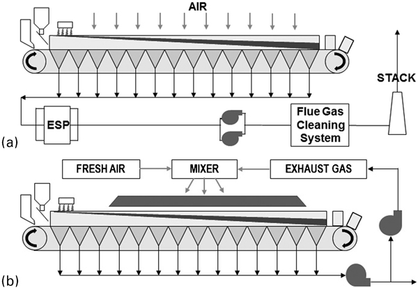
a normal sintering plant configuration; b sintering with flue gas recirculation (FGR)
Controlling the condition of the input gas is one of the major operational parameters, and has a strong influence on the overall process. As a certain fraction of the flue gas is recirculated, the conditions of the supplied inlet gas and exhaust gas will be changed in terms of temperature, composition (especially oxygen and moisture contents) and flowrate. Changes in input or outgoing gas conditions may have unfavourable effects on the sinter bed reactions or on the production of sintered ore, as revealed in previous research which dealt with different oxygen and moisture levels in the input gas, or the features of selective recirculation for desulphurisation and steam injection. 11,12 For instance, oxygen and moisture contents in recirculation gas are pivotal factors for sintering operations because they are related to evaporation heat loss, insufficient oxygen supply for combustion, worsened bed permeability and disturbing gas flows across the bed. In addition, the requirements of plant equipment such as ducts, injection hoods, fans or blowers, and gas cleaning equipment for FGR will vary in relation to the different gas properties.
Moreover, the operating variables of the sintering process can be seriously affected by system configuration. For instance, location of the exhaust gas extraction can be varied depending on the main focus of the system modification; for example, bed elongation to improve sinter production or control of pollutant emissions such as CO2, SOx, NOx or dioxin. Locations of recirculation gas injection also can be varied to cover specific areas of the bed, or to inject additional gases, such as oxygen and liquefied natural gas. The flue gas recirculation ratio, or the amount of flue gas for recirculation, needs to be determined by considering the capacity of related equipment and input gas conditions simultaneously, otherwise leakages may occur in the gas flow lines, or the system may fail to secure the proper amount or proper conditions of gas flow for combustion and related reactions.
Therefore, as the application of FGR has an inevitable impact on the conventional sintering process, the importance of investigating its effects on gas conditions across the bed, as well as on the plant design and operational factors, is increased. Location of the flue gas suction and injection, the recirculation ratio or flowrate, the input gas condition control and the setting-up of relevant equipment should be properly determined, while maintaining sintering time, quality and productivity. Issues related to the design and operation of iron ore sintering plants with an FGR system can be summarised as shown in Fig. 5.
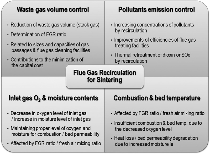
Issues related to FGR sintering plants
Application of flowsheet process simulator
Modelling of a sintering bed in this study was intended to aid the design and operation of sintering plants in various circumstances. The model focuses mostly on the incoming and outgoing gas conditions from each segment of the bed. For FGR sintering, input gas conditions need to be set up differently for each section of the bed according to the configuration of gas recirculation. Different input gas conditions result in varied outlet gas conditions, which in turn are partially reflected in input gas conditions. Moreover, material flows of solids and gases become complex, and models may require simplification to avoid computational difficulties. Therefore, the previous approach, which performed iterative calculations focusing on the details in the bed with the lapse of time, may be inefficient in proposing precise input conditions over various process configurations, and when investigating material properties.
Flowsheet process simulation programmes have been widely used as an appropriate tool for process design and analysis. They are used to study potential changes in operating conditions or the possibility of a retrofit for process improvement. In general, calculations of subroutines, which represent the performance of process equipments, are performed unit by unit, and thus this solution method is referred to as a sequential–modular model. Process simulators deal with a collection of equations related to physical property correlations of thermodynamic and transport properties, material and energy balances for process units, and connectivity of units and streams in the flowsheet, together with mathematical algorithms for the iterative convergence of recycling loops. Process simulators can solve such equations for many of the unknown variables, based on known information and the database of material properties, to give a material and energy balance of subroutines, as well as information on the properties of streams, in the flowsheet process model.
In this study, a commercial flowsheet process simulator, Aspen Plus, was utilised for the modelling of a steady state sintering bed process. Several previous studies on sintering and the steelmaking process used flowsheet process simulators focused on pollutant emission or decision support. A proper level of modelling with process simulators is regarded as a tradeoff between descriptive detail and simplicity or flexibility. 15–17 Although a model built using flowsheet process simulators may not fully provide sufficient details for all physicochemical phenomena, its application to obtain stream properties or mass and energy balance calculations for sintering beds, especially for gas flows, will be beneficial for the purpose of modelling and efficiency. The modelling in this study will allow information on incoming and outgoing material flows to be expressed and compared quantitatively to calculate the factors of interest, such as gas temperature, concentrations, especially oxygen and moisture contents, and flowrates and other properties.
Modelling method
Modelling approach
Basically, the aim of the modelling procedure is to discretise the bed into a finite number of segments along the bed length and depth, where the material properties are homogeneous within the region. The following simplifying assumptions were made in describing the sintering bed:
the sinter bed was simplified to a two-dimensional area in the direction of the bed length and height. Changes in properties across the width were not considered
there was no change in the bed height along the bed length
the ignition and discharge regions were omitted
the bed was divided into consecutive columns according to the corresponding wind boxes
combustion zone expansion along the bed length is not considered, which is the most important simplifying assumption. Therefore, every column was assumed to have the same amount of reacting materials and flowrates throughout the bed
regarding (v), the pressure drop of gas flow through the bed was ignored
heat or material losses during the process were neglected.
The conceptual bed area for the model is shown in Fig. 6a . The assumption of no combustion zone thickness expansion along the bed length may bring a noticeable difference of mass or volumetric flowrates between the real situation and the model. Nevertheless, the simplified assumption is applied for the purpose of modelling so to compare the effects of different system configurations with FGR. The means of reaction rate simplification is illustrated schematically in Fig. 6b . In the real plant, combustion gas flows through ducts beneath the sinter bed, known as wind boxes, to waste gas cleaning facilities and the exhaust stack. A line of wind boxes is attached one by one under the sintering bed and covers the entire bed length. Since those wind boxes have similar dimensions, it can be assumed that each wind box covers the same length of the bed. In a similar manner, the entire length of the sintering bed was divided into consecutive sections (14 in the model) which are represented by columns (longitudinal direction L), and are shown in Fig. 6c .
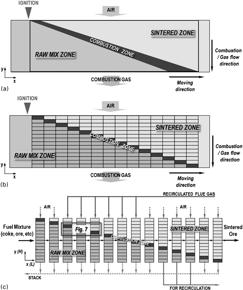
a conceptual description of bed area under consideration; b simplified and discretized sub-zones; c air and combustion gas flow lines with FGR
A column was composed of a number of layers (height H) to distinguish the sintered zone, the combustion zone and the raw mixture zone of the bed. Figure 7 represents the shaded area in Fig. 6c and illustrates the schematic structure of the segments in the process model. Figure 7a shows the interrelation of the column and layer segments to the considered reactions. In the figure, X represents the gas (species j), M is the solid material (species i), L is the total number of columns (subsection l) and H is the total number of layers (subsection h). The number of layers representing the sintered zone was set to increase, and the raw mixture zone decreased, along the bed length in the direction of sintering progression. Solid materials were supplied to the layers of the first column and conveyed to the same layers of the next column. Air or oxidant gas was distributed and supplied separately to all columns. An inlet gas stream was connected to move from the top layer to the bottom layer in a column. Flue gas, or exhaust gas, from the columns were mixed together as the exhaust stack gas.
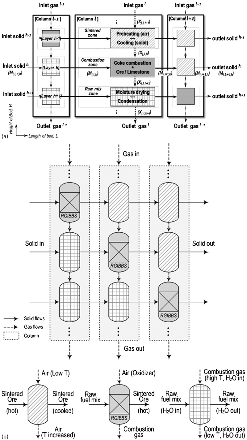
a interrelation of blocks neighbouring the combustion zone (column l, layer h); b conceptual description of the model with process units
In the process model, calculations of chemical and phase equilibrium or material and heat balances were performed by a combination of subroutines, also called unit models in the simulator, including RYIELD, RGIBBS, MIXER, FSPLIT, FLASH, SEP and stream manipulators. These units were arranged to constitute columns, stream flows and the entire bed in such a way to represent the structure of layers and the sequence of reactions from the bed top to the bottom, as illustrated schematically in Fig. 7b .
In the combustion zone, the reactions of coke combustion, haematite reduction and reoxidation, and limestone decomposition were mainly considered. These were treated by RGIBBS reactor units which perform Gibbs free energy minimisation for equilibrium calculations. No details of the reactions need to be defined directly for an RGIBBS unit, but possible reactions can be selectively implied by specifying input and product components. Above and below the combustion zone, no other chemical reactions were considered, but temperature changes, as well as moisture evaporation and condensation were treated by FLASH units in a similar manner to calculate dewpoint. Since solid material in the sintered zone, including iron oxide, CaO, CaFe2O4, ash and inert material, is the hot product from the combustion zone with little moisture, temperature changes of the solids and gas flows are the most representative reaction here. The temperatures of the solid materials on either side of the segment for combustion are always lower than the calcium ferrite fusion temperature. Evaporated moisture is transferred downwards along with the gas flow streams. The composition of solid material in the raw mixture zone is as fed into the first column, but temperature and H2O mass fraction will be varied by hot gas streams and moisture transferred from the upper layers.
Input material conditions were determined referring to the previous studies, as presented in Tables 1 and 2. 3,4 Supply rates were assumed to be 13·37 kg min−1 for solid fuel and 8227·7 L min−1 for air. Iron ore was considered to be haematite for the feed material. The gaseous species considered were N2, O2, CO2, CO, H2 and H2O. Peng–Robinson equation of state model was applied as the physical property model. Coke and inert material were set as user defined materials, also called a ‘non-conventional component’ in Aspen Plus, which requires particular property models with user input data. Coke enthalpy and density were calculated with HCOALGEN and DCOALIGT models in the simulator respectively, based on the coke analysis data of Table 2, including proximate, ultimate, sulphur analysis and heat of combustion. Inert material refers to material included in the fuel mixture but not participating in the reactions. Inert material enthalpy and density were calculated with ENTHGEN and DNSTYGEN models in the simulator respectively, based on user specified heat capacity and density parameters (see Table 2).
Input material conditions for modelling
Inputs for user defined components in model
Discussion of availability and limitation
Employing a flowsheet process simulator, the sintering bed process model provides comprehensive information on solid and gaseous material flows, which can be easily utilised in a quantitative manner. Property information may include not only temperature, pressure and composition, but also total and component flowrates, enthalpy, entropy, flowrate, density and viscosity of all material streams on both a mass and molar basis. Moreover, the model was built to deal with the entire bed as the subject in consideration of FGR. Therefore, setting up the process configuration for FGR can be easily and intuitively specified, i.e. the determination and variation of flue gas extraction and input gas supply locations, the recirculation ratio or fresh air mixing ratio and the amount of sintering product. These features of the process modelling seem to be more beneficial in analysing the sintering process with FGR. In addition, the existence of recirculation gas flow implies the need to deal with recycle loops in such a way that, once obtained, the result is processed so to be reapplied as an input condition, which is known to be capable of provoking convergence problems occasionally. These problems can be handled efficiently in the model by differentiating selections of convergence methods and their parameters in a simple way. Therefore, the model can be applied conveniently to various input conditions and process configurations for FGR.
The results of the parametric study will be discussed in the companion paper, with a focus on incoming and outgoing gas conditions, to investigate the effects of FGR on the sintering process. As fundamental results of the model, the distribution of flue gas temperature and concentration, especially oxygen and moisture contents, along the bed length, can be obtained. Some of the examples of results available from the model are summarised in Fig. 8, which shows graphical distributions of flue gas temperature, composition and H2O mass fraction.
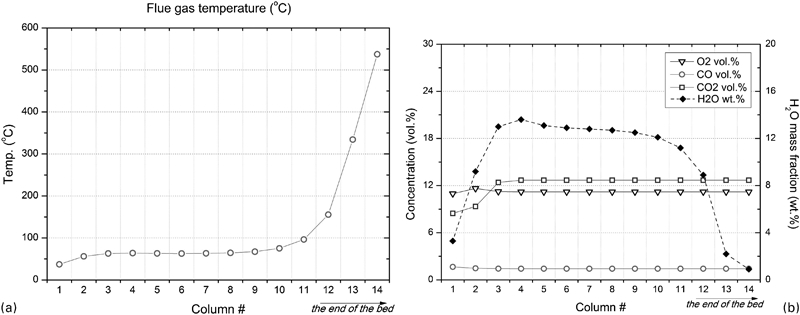
a flue gas temperature distribution; b flue gas concentration (dry, vol.%) and H2O mass fraction (wt.%)
Based on these results and the stream information, further analysis and comparisons among process configurations and operating conditions can be made. For instance, the change in temperature and composition of the incoming gas under the FGR sintering process can be shown. At the same time, the amounts of flue gas exiting from the bed, extracted flue gas for recirculation, and stack gas, together with their properties, can be checked. The same procedure can be applied to other process configurations which have different locations for flue gas extraction and injection, different FGR ratios and different fresh air mixing ratios for incoming gas. By comparing results between different cases, ideas for process improvement, such as determination of the proper locations for recirculation or the proper FGR ratio can be reviewed. Moreover, a parametric study can be conducted by controlling operational factors such as coke or moisture content in the feed material or the temperature of the raw material zone and the incoming gas. The approach is also expected to be utilised for other process of controlling techniques such as oxygen enrichment and fuel gas injection in the sintering process.
Conclusions
Implementing FGR as an improvement for the iron ore sintering process inevitably brings changes to gas conditions to the sintering bed. Decreased oxygen levels and increased moisture content may have unfavourable effects on the sintering process. Additional gas flow lines will be required for the gas circulation system, which may necessitate changes in gas flowrate control or requirements for gas cleaning facilities. Therefore, the effects of the application of FGR to the iron ore sintering process need to be carefully investigated, considering the importance of the gas conditions for the sintering process.
In this study, modelling of the sintering bed was proposed and conducted using a commercial flowsheet process simulator. A process model was built by representing the general structure of the sintering bed and related reactions, referring to the results of previous research, with assumptions for simplification. It is expected that temperature, composition and flowrates are major factors for gas conditions in the model. Owing to flexibility in constructing the modelling structures, the model will be useful for various plant configurations with FGR. Results from the model can be used to predict possible material conditions flowing in and out of the bed, such as supplied recirculation gas properties or waste gas flowrates, and variations of those conditions according to the input changes.
Since the model in this study is mainly focused on the conditions of gas flows, it may not fully reflect situations in the sintering beds of commercial plants. The model will require additional work for more detailed information than could be achieved using simplified assumptions. However, the proposed approach of the flowsheet process model for the sintering bed is thought to be efficient for plant engineering design or operational control of the process because it can provide additional information about material and energy flow throughout the system.
Footnotes
Acknowledgements
This research was supported by POSCO and Brain Korea 21 Project (BK21).