
Abstract
Two-dimensional thermo–elastic–plastic creep finite element models of two beam blank moulds with different water slot designs, the large hole mould and the small hole mould, are set up and their thermomechanical behaviour is numerically investigated by means of ABAQUS software. The temperature, distortion, stress and inelastic strain range across the hot faces as well as the fatigue life of the two moulds are discussed in detail, based on which it is shown that the distributions of temperature and distortion of the small hole mould are more uniform than those of the large hole mould, and the peak temperature of the former mould is smaller than that of the later mould. However, the fatigue life of the small hole mould is shorter than that of the large hole mould. Both moulds were put into service in an industry and it is demonstrated that the quality of the product cast by the small hole mould is better than that by the large hole mould, and the service life of the small hole mould is longer than that of the large hole mould because the service life of a mould chiefly depends on the wear of its hot face, which is much shorter than the fatigue life. An improved water slot design for the beam blank mould is then proposed and it is numerically demonstrated that this improved mould is superior to the large hole mould and the small hole mould.
Introduction
Since its introduction at Algoma Steel in Canada in 1968, 1 beam blank casting with its lower production cost and higher productivity has become an excellent alternative to the conventional bloom casting route for the production of beams and sections. Owing to the complex cross-section shape of the beam blank, the distribution of temperature, distortion and stress of both of the mould and the strand are complicated, which usually induces product defects and shortens mould service life. Therefore, quality improvement of the beam blank and mould service life of extension are very important.
The design of water slots in a mould greatly influences the heat removal, thermal distortion and stress of the mould and the strand and, in turn, the product quality and mould service life. Many efforts have been made to understand the influence of water slot design on the thermomechanical behaviour of continuous casting moulds and to improve the scheme of water slots. Hashimoto et al. 2 numerically analysed the temperature, stress and distortion in slab casting moulds using a finite element model, and indicated that the presence of horizontal water slots has little effect on the prevention of mould plate deformation, and the root shape of the vertical water slots has some influence on cracking and service life of the mould plate. Thomas et al. 3 investigated the effect of spacing, depth and root shape of water slots on the distribution of temperature and stress of a slab mould by means of a three-dimensional (3D) thermo–elastic–plastic creep model, and concluded that water slots should be extended as close to the top, bottom and edges of the mould as possible. Using a 3D heat transfer model, Langeneckert 4 and Thomas et al. 5 studied the heat transfer in a slab mould with different cooling water slot geometries in order to improve the hot face temperature uniformity. Peng et al. 6 proposed an improved scheme of cooling water slots of a slab mould based on the 3D thermo–elastic–plastic finite element simulation.
However, the aforementioned work focused on a mould with simple geometry, and only a few efforts have invested beam blank moulds with complex cross-section shapes. To minimise the peak temperature and to improve the uniformity of temperature around the hot face perimeter of the mould, Thomas et al. 7 optimised the water slot design of a beam blank mould by means of two-dimensional (2D) finite element heat transfer analysis, lacking stress analysis and plant data. Hibbeler et al. 8 developed a 3D thermomechanical finite element model to predict temperature and distortion of a beam blank casting mould, but the distortion of the mould was not discussed in detail and little attention was paid to the effect of water slot design on product quality and mould service life. Recently, Xu et al. 9,10 investigated the influence of cooling water slot design on product quality and mould service life utilising 2D heat transfer models, without taking the stress and distortion of the mould into account. Thus, further research is needed to investigate the thermomechanical behaviour of the beam blank mould with different water slots and to improve the design of the water slots to obtain better product quality and longer mould service life.
In this paper, 2D thermo–elastic–plastic creep finite element models of two beam blank moulds, a large hole mould and a small hole mould, were established and their thermomechanical behaviour was numerically analysed by means of ABAQUS software. Based on the numerical investigation and plant trails of these two moulds, an improved water slot design, which is superior to both these moulds, is proposed.
Thermal stress numerical model
Model description
A beam blank mould is typically made of copper alloy, usually Cu–Cr–Zr and is constructed with four separate copper plates, the two wide face plates and the two narrow face plates bolted to back-up plates. To resist wear, a nickel layer is coated on the hot face of the plates. During operation, the mould is cooled by forced circulation of water flowing in the square and the annular water slots. The cross-section of a typical beam blank mould is shown in Fig. 1.
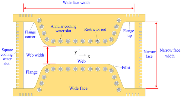
Cross-section of typical beam blank mould
The thermomechanical behaviour of two beam blank moulds, the large hole mould and the small hole mould, whose quarter cross-sections are shown in Fig. 2, was first investigated. Except for the water slot design, the structural parameters of the two moulds are the same. There is a restrictor rod in each hole of the large hole mould, as shown in Fig. 2a , and the diameters of the hole and the rod are 30 and 25 mm respectively. However, there are no restrictor rods in the small hole mould, as shown in Fig. 2b , and the diameter of each small hole is 10 mm. The size of each square cooling water slot is the same for the two moulds at 18×5 mm.
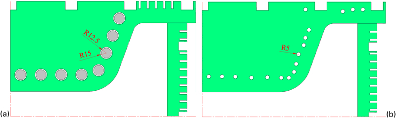
Quarter cross-section models of a large hole mould and b small hole mould
Owing to the symmetry of geometry, boundary condition and mechanical load, the quarter cross-sections of the two moulds as shown in Fig. 2, 120 mm below the meniscus, are chosen as the numerical models. The simulation conditions and material properties of the two moulds are the same and listed in Table 1 Tables 1 and 2. These 2D models are assumed to deform in plane strain and the longitudinal heat conduction is ignored. 7,9,10 It is noted that the 0·3 mm nickel layer is taken into account in the finite element models.
Simulation conditions
Material properties of moulds 11
Heat transfer model
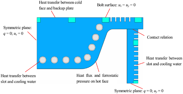
The 2D heat transfer governing equation for the mould copper plates can be expressed as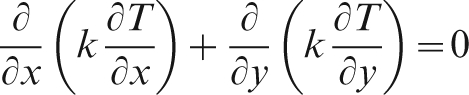
The thermal boundary conditions for the heat transfer analysis, as illustrated in Fig. 3, are described as follows:
Thermal and mechanical boundary conditions
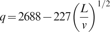
The heat flux on the hot face of a mould is determined by the following empirical equation
9,10,12
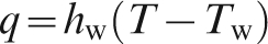
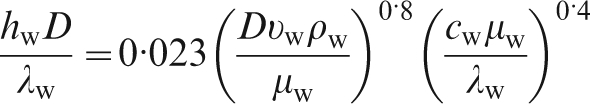
The heat flux between the cooling water and the copper plates is given by
3–10
Between the mould cold face and back-up plate, the heat transfer coefficient is assumed to be 1161 W m−2 °C−1 for the both moulds.
The adiabatic boundary condition q = 0 is applied on the symmetric planes of the two moulds.
Stress model
The total strain increment dϵ
total can be separated into four parts during stress analysis as
The load and displacement conditions for the stress analysis, as specified in Fig. 3, are described as follows:
The deformation of the bolts connecting the copper plates and the back-up plates is assumed to be negligle, so fixed conditions u x = 0 and u y = 0 are specified on the outer surfaces of the six bolts. It is noted that the bolts are tied with the copper plates in the numerical models.
Symmetric displacement boundary condition u x = 0 is specified on the symmetric plane of the wide face, and the condition u y = 0 on the narrow face.
The ferrostatic pressure determined by p = ρgL is applied on the hot face.
In addition, the contact relation between the wide face and the narrow face of the mould is defined and the friction coefficient is set to be 0·1.
Numerical simulation procedure
The steps to simulate the thermomechanical behaviour of the beam blank moulds during casting are as follows:
rapidly heat the mould from ambient temperature to operating temperature under the heat transfer, load and displacement conditions described in the last section
keep the thermal and mechanical loads for 8 h to simulate the thermal creep effect of the mould
cool the mould down to ambient temperature
repeat steps from (i) to (iii) to simulate the thermomechanical cycles experienced by the mould in service.
Thermomechanical behaviour of two moulds
Temperature distribution during operation
The temperature contours and distorted shapes of the quarter models of the two moulds in simulated operation conditions are listed in Table 1, and as numerically analysed by ABAQUS software are shown in Fig. 4. It can be seen that the peak temperature, 337·7°C, of the large hole mould locates at the fillet, where overheating takes place due to the convergence of heat flow from the web and the flange. However, the peak temperature of the small hole mould occurs on the hot face of the web at the lower value of 316·1°C. The temperature profiles across the hot faces of the two moulds during operation are shown in Fig. 5, from which it is observed that the temperature profile on the hot face of the large hole mould fluctuates greatly, and with a peak at the fillet, two valleys respectively at the flange corner and the intersection between the wide face and the narrow face occur. On the other hand, the temperature profile on the hot face of the small hole mould is comparatively smooth except in the vicinity of the intersection between the wide face and the narrow face.
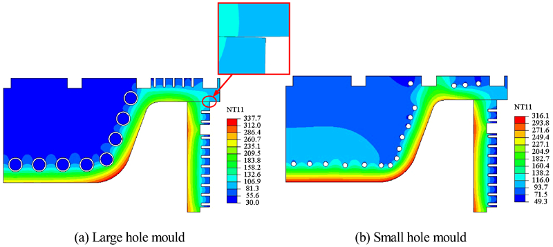
Temperature contours and distorted shapes of a large hole mould and b small hole mould during operation (distortion is amplified by 10 times)
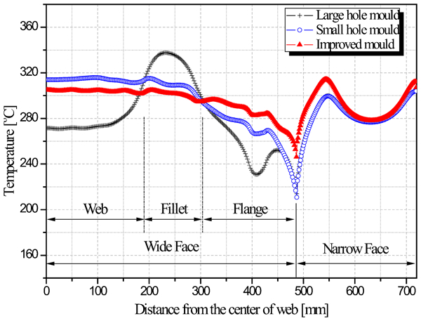
Temperature profiles across hot faces of moulds during operation
It is known that the product quality and mould service life depend on the magnitude and uniformity of hot face temperature.
7
Higher temperature not only increases inelastic strain of the mould during each thermal fatigue cycle, but also increases surface embrittlement of the mould due to grain boundary segregation. In addition, non-uniform temperature distribution on the hot face usually leads to uneven expansion and stress concentration of the mould. The difference between the maximum temperature T
max and minimum temperature T
min on the hot face T
max−T
min and the standard deviation of temperature on the hot face T
sd are usually employed to evaluate the temperature uniformity on hot face. The standard deviation of temperature T
sd is defined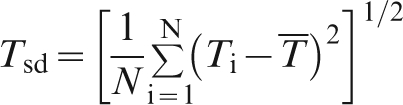

Temperature characteristic parameters on hot face of moulds
It can be seen from the data in Table 3 that the parameters T max, T max−T min and T sd of the large hole mould are larger than those of the small hole mould, which means that the temperature level on the hot face of the small hole mould is lower and the temperature distribution is more uniform than those of the large hole mould. This infers that better quality of beam blank may be obtained when the small hole mould is employed.
Mechanical behaviour during heating and cooling cycles
The procedures consisting of 10 cycles, in each of which thermal and mechanical loads are kept constant for 8 h, of heating and cooling of the two moulds are numerically simulated. The loops of the stress–strain components in the x direction at a typical point on the hot face of the small hole mould during the 10 cycles are shown in Fig. 6. It is seen that the steady state is achieved rapidly after the first cycle. During the heating process, the mould temperature arises from ambient temperature to operating temperature, and the mould tends to expand towards the molten steel, but is constrained by the bolts on the back-up plate, which induces compressive stress in most portions of the mould.
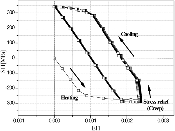
Loops of stress–strain components in x direction at typical point of small hole mould
The stress–strain loops at the same typical point on the hot faces of the large hole mould and the small hole mould during the tenth heating and cooling cycle are shown in Fig. 7. It can be seen that the strain range, which determines the low cyclic fatigue life, of the small hole mould is larger than that of the large hole mould, although the stress range of the former mould is smaller.
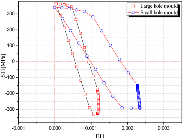
Stress–strain loops at typical point of large hole mould and small hole mould in tenth cycle
As mentioned above, the stress–strain loops of a mould arrive at steady state after the first cycle. The distortion of the small hole mould at the operating state in the tenth cycle is shown in Fig. 4. It is seen that the wide face pivots away from the narrow face and the maximum gap between the wide face and the narrow face is 0·06 mm during operation, which is very small. The distortion profiles across the hot faces of both moulds during operation are illustrated in Fig. 8, from which it is seen that the maximum distortions of the two moulds appear in the zone of the fillet at 0·572 and 0·657 mm for the large hole and small hole moulds respectively. Although the distortion of the hot face of the small hole mould is larger than that of the large hole mould, the former is more uniform. Non-uniform distortion of the hot face may lead to non-uniform gap between the mould and the strand, which will result in the non-uniform heat transfer from the strand to the mould, and induce the non-uniform deformation and defects in the strand. Moreover, it is seen that in the fillet of the large hole mould, the hot face rises, which may give rise to contact between the mould and the strand and more wear of the hot face of the mould in this zone.
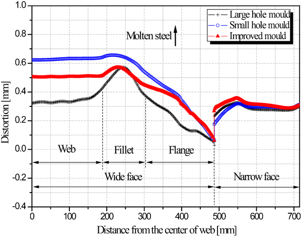
Distortion profiles across hot faces of moulds during operation
From Figure 6 Figs. 6 and 7, it can be seen that the expansion of the moulds leads to compressive stresses on their hot faces during operation, which generally causes little damage to the mould. In the 8 h at constant operating temperature, creep or stress relaxation takes place in the moulds. Upon cooling to ambient temperature, the hot faces of the moulds change into a tension state. The von Mises stress profiles across the hot faces of the two moulds after cooling are shown in Fig. 9, from which it is known that the stress distributions on the hot faces of the two moulds after cooling are nearly the same.
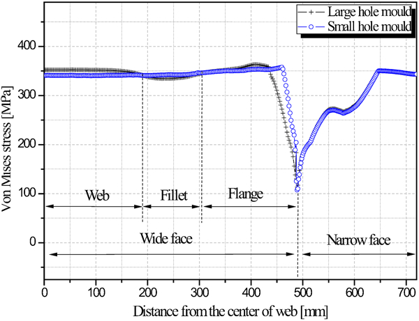
von Mises stress profiles across hot faces of large hole mould and small hole mould after cooling
Alternative stress and/or strain during heating and cooling cycles may lead to fatigue failure of the moulds. The fatigue life of a mould depends on the inelastic strain range in thermomechanical cycles, and the inelastic strain ranges profiles across the hot faces of the two moulds in the tenth cycle are shown in Fig. 10. It can be seen that the inelastic strain range profile across the hot face of the small hole mould is the larger in most of the region, and this means that the fatigue life of the small hole mould will be shorter.
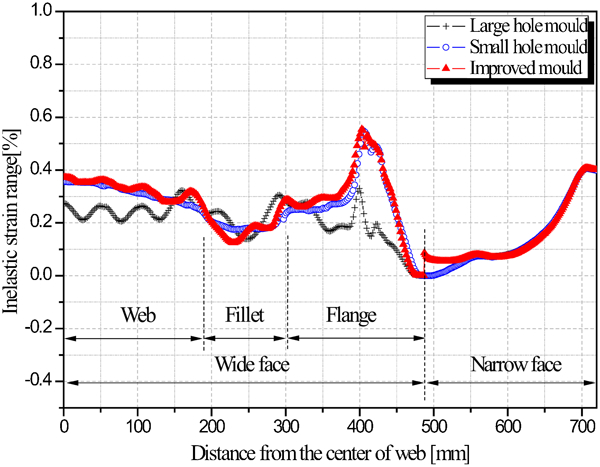
Inelastic strain range profiles across hot faces of moulds in tenth cycle
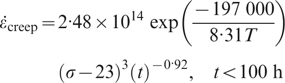
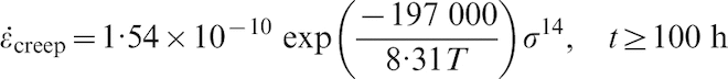
Based on experimental data, Ashida and Takao
14,15
presented the following formula
Fatigue life prediction of moulds
Plant trails
Both the large hole mould and the small hole mould were put into service at the same time at a steel plant in Maanshan Iron and Steel Co., Ltd in China. During the trial period, the product quality and mould service life for the two moulds were investigated.
The typical surface microstructures of the beam blanks at different locations of SS400 steel cast by the two moulds are shown in Fig. 11. A higher temperature mould hot face will induce a lower cooling rate to the strand, which causes coarse grains on the strand surface, and vice versa. From the temperature profile across hot face of the large hole mould, as shown in Fig. 5, higher temperature occurs in the fillet and lower temperature occurs in the other zone, so coarse grains and inhomogeneous microstructure are observed in the fillet and fine grain and uniform microstructure are observed in the flange tip, as shown in Fig. 11a . On the other hand, the temperature profile across the hot face of the small hole mould is more uniform, as shown in Fig. 5, the surface microstructures at different locations of the beam blanks cast by the small hole mould are more uniform as shown in Fig. 11b .
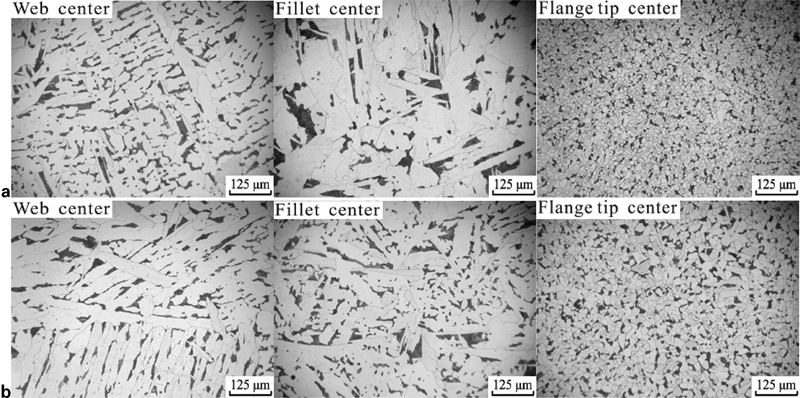
Surface microstructures of SS400 steel cast by a larger hole mould and b small hole mould 9
It is known that the service life of a beam blank mould depends on the wear of its hot face, which is mainly induced by the abrasion against the strand, and on the embrittlement of the hot face due to high temperature during casting. 7,9 The test results in the plant trials show that the service lives of the small hole mould and the large hole mould are 1200 and 1000 heats respectively, which are much shorter than the predicted fatigue lives determined by the numerical simulation in Table 4. It is seen in Fig. 8 that the distortion in the fillet of the large hole mould and the small hole mould is larger than other zone on the hot face. This means that the larger distortion of the fillet may lead it to contact with the strand and wear more easily. Moreover, the hot face in the fillet of the large hole mould rises, which may induce contact between the mould and the strand and the wear of the hot face of the mould in the zone more easily. On the other hand, the embrittlement of the hot face in the fillet of the large hole mould takes place more easily than that of the small hole mould because the temperature of the hot face in the fillet of the former mould is higher, as shown in Fig. 5. Therefore, longer service life of the small hole mould is observed in the plant trials.
Product quality is mainly controlled by the crack rate generated in a strand, which is defined as the mass ratio of the cast strand with surface cracks to the whole strand. The crack rates of the beam blanks cast by both moulds after 500 heats and 1000 heats are shown in Fig. 12, from which it is seen that the crack rates of the beam blank cast by the small hole mould are 0·47 and 1·77% respectively after 500 heats and 1000 heats, which are 4·10 and 6·85% less than thode from the large hole mould. These results demonstrate that the product quality greatly relies on the temperature and distortion distributions along the hot face of the beam blank mould. Large temperature gradients and uneven expansion across hot face of the mould may lead to non-uniform cooling on strand surface, resulting in the formation of crack on the strand surface.
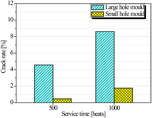
Crack rates of strands cast by large hole mould and small hole mould
The plant trails show that the quality of beam blank cast by the small hole mould is better than that by the large hold mould, and service life of the small hole mould is longer than that of the large hole mould. Combined with the numerical results, it is concluded that lower peak temperature, more uniform distributions of temperature and distortion across the hot face of the mould are beneficial to higher product quality and longer mould service life.
Improved water slot design
According to the above discussion, it is known that water slot design may strongly influence the temperature and distortion distributions of a mould. By adjusting the position and dimension of water slots, a lower peak temperature, smaller temperature gradient and more uniform thermal distortion across the hot face can be obtained. An improved design of water slots for a beam blank mould is proposed and shown in Fig. 13.
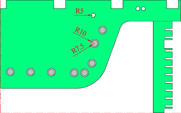
Quarter model of beam blank mould with improved water slot design
Here the arrangement of the square slots is the same with that of the small hole mould, and large hole slots, in each of which a restrictor rod is placed, and small hole slots are also positioned in the wide face. The diameters of each large hole and each rod are 20 and 15 mm respectively, which are smaller than those of the large hole mould, and the diameter of the small hole is 10 mm, which is the same with that of the small hole mould. It is seen from Figure 2 Figs. 2 and 13 that the large hole slots in the large hole mould are arranged evenly and nearly parallel to the hot face, but the large hole slots in the improved design are unevenly distributed. Moreover, the number and position of the small hole slots in the improved design are different from those of the small hole mould. It is noted that although large hole slots are used in the improved design, their dimension and position are different from those of the large hole mould.
The numerical model of the mould with improved water slot design, now termed the ‘improved mould’, was set up and the thermomechanical behaviour was simulated by ABAQUS software. The simulation conditions and the material properties of the mould are the same as earlier trials. The numerical results and the comparisons between the various moulds are discussed below:
The temperature profile across the hot face of the three moulds are shown in Fig. 5 and it is shown that more uniform temperature distribution and lower peak temperature on the hot face of the wide face are obtained with the improved mould. Moreover, the temperature characteristic parameters T max, T min, T max−T min and T sd, of the improved mould are listed in Table 3, from which it is seen that T max, T max−T min and T sd, are smaller and T min is larger than those of the other two moulds, which reflects that the uniformity of the temperature of the improved mould is better. Therefore, higher product quality should be obtained.
The distortion profile across hot face of the improved mould during operation is shown in Fig. 8, from which it is known that the maximum distortion of the improved mould appears in the zone of the fillet, and the distortion of the hot face is more uniform than that of the other two moulds. Thus less wear should place and longer mould service life should result when the improved mould is used.
The predicted fatigue lives of the improved mould at three typical positions on the hot face based on the numerical simulation are listed in Table 4. It can be seen that the fatigue life of the improved mould, based at 399 mm from the wide face centre, is shorter than those of the other two moulds. However, it has been demonstrated that the service life of the beam blank mould is determined by the wear of the hot face, which depends on the temperature and distortion distributions of the hot face, but the fatigue life.
Conclusions
Two-dimensional thermo–elastic–plastic creep finite element models of the large hole mould and the small hole mould were set up and their thermomechanical behaviour was numerically investigated. Based on the numerical investigation and plant trials, an improved water slot design is proposed. It is concluded that:
The distributions of temperature and distortion across the hot face of the small hole mould are more uniform than those of the large hole mould, and the peak temperature of the small hole mould is smaller than that of the large hole mould.
The inelastic strain range of the larger hole mould is smaller than that of the small hole mould, and its fatigue life is longer. However, the service life, which depends on the wear of the hot face, is longer for the small hole mould.
The plant trails demonstrate that the quality of products manufactured by the small hole mould was better than that by the larger hole mould, and the service life of the small hole mould is longer than that of the large hole mould, which are consistent with those of the numerical simulation results.
An improved water slot design is proposed for the beam blank mould, and it is shown by numerical simulation that better product quality and longer mould service life may be obtained. It is suggested that the improved water slot design be applied in the beam blank mould.
Footnotes
Acknowledgements
The authors wish to thank the financial supports from National Science and Technology Pillar Program in the eleventh Five Year Plan of China (project no. 2007DAE30B01).