
Abstract
The solidification structure of 6.5%Si steel ingot was simulated based on the cellular automaton–finite element (CAFE) method and compared with an actual casting. The results showed that both the average grain size and proportion of columnar crystals agreed well with the experimental ones. The parameters suitable for simulating the microstructure of 6.5%Si steel ingot were determined. The influence of superheat and cooling conditions on the solidification structure was also studied in detail. The results show that the proportion of columnar crystals decreases with decreasing superheat, and the average grain size becomes smaller. The microstructure under the condition of slow cooling is finer than of air cooling.
Introduction
Silicon steel is one kind of electrical steel, widely used in the manufacture of generators, motors, transformers and other electric components. 1 Its magnetic characteristics such as near zero magnetostriction, high permeability, high resistivity, low noise and low core loss 2 are improved by increasing Si content and optimised at 6.5 wt-%Si. However, when the Si content increases, the material becomes brittle and difficult to work by conventional hot/cold rolling processes. Therefore, the Si content is usually controlled ∼4.5% in industrial production.
Currently, several fabrication methods have been developed in Japan and elsewhere to avoid the brittleness of 6.5%Si steel, including chemical vapour deposition, rapid solidification, special rolling etc., but there are also many shortcomings, such as expensive equipment, high maintenance, environmental pollution, low yield, etc. 3 Steel (6.5%Si) cannot be made according to traditional production processes due to the large grain size and developed columnar crystals in the solidification structure of the ingot, which leads to cracking and other defects in casting and subsequent processing. 1 Therefore, controlling the solidification structure has great significance in producing excellent ingot casting and improving performance of rolling.
The numerical simulation models of the formation of microstructure used to study the dendrite are deterministic, stochastic and phase field models respectively. The stochastic model takes into account the random factors in the solidification process and is often used to study nucleation and growth of grains, including the random distribution of nucleation sites and random selection of crystallographic orientation. 4 In the 1990s, Gandin et al. 5,6 built the macro–micro-FE-CA coupling model which coupled methods of cellular automaton (CA) and finite element (FE). With the help of a cellular automaton–finite element (CAFE) model, many researchers 7–11 successively simulated the formation of the microstructure during metal solidification, and the results were validated by experiments. However, the microstructure simulation of 6.5%Si steel based on the CAFE method has seldom been reported. Therefore, the aim of this paper is to simulate microstructure of 6.5%Si steel during the solidification based on the CAFE method.
In the present research, a 6.5%Si steel ingot casting was produced in a 200 kg vacuum induction furnace, its microstructure was obtained and the physical characters of the CAFE method are discussed. Cellular automaton–finite element modules of the finite element software ProCAST were employed to investigate the solidification structure of the casting, and the influence of different superheat temperatures on the solidification structure under different cooling conditions and grain size was also compared.
Mathematical model of CAFE
Macroscopic thermal transport
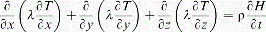
Neglecting convection in the liquid zone, the temperature field obeys the non-stationary heat flow equation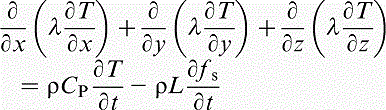
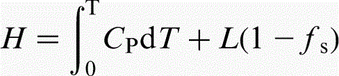
The release of latent heat in metal solidification is a significant characteristic that can divide solidification processing from other heat conduction process, which is also the bond between the macroscopy and microscopy in solidification processing. The release of latent heat is also derived from nucleation and dendritic growth in the microscopic field; meanwhile, latent heat released from dendritic growth is fed back to calculation of temperature field. Therefore, enthalpy is used as a variable rather than temperature in the computing of latent heat in CAFE simulation
12
Microstructure model
Heterogeneous nucleation model
In the process of microstructure simulation, there are two mechanisms of nucleation: homogeneous and heterogeneous. Heterogeneous nucleation has more practical significance in actual production. There are also two ways to treat heterogeneous nucleation: instantaneous nucleation and continuous nucleation. Rappaz and Gandin
4
assumed that instantaneous nucleation may occur in a range of possible sites. If there is no nucleation site in a cell, nucleation will not occur no matter how low the temperature. Conversely, new nucleation will be formed randomly in the bulk volume as a result of the fall of local temperature of the nucleating cell below the critical temperature in the given time step. At any undercooling temperature, the number of nucleation sites in the liquid steel is expressed by the following equation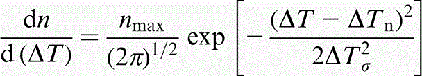
Dendrite tip growth kinetics model
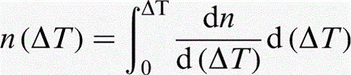
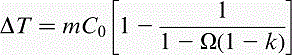
In the solidification process of an alloy, the total undercooling of the dendrite tip ΔT is generally the sum of four contributions
Coupling FE with CA model
As can be seen from Fig. 1, interpolation coefficients are defined between nodal points of the FE mesh and CA cells, and introducing the influence of the latent heat release of the grains on the calculated thermal history in order to predict the microstructure development as a function of the thermal field. The CA cell ν, with its centre in the finite element I, has non-zero interpolation coefficients, Φνi, Φνj and Φνk with the FE nodes i, j and k respectively. These interpolation coefficients allow the determination of the temperature at the cell locations at the FE nodal points. At the nodal points, the same coefficients were adopted to sum up the latent heat released by nucleation, growth and the thickening of the dendritic microstructure, updating the temperature at the FE nodal points. 14
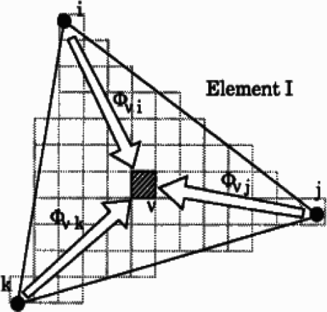
Schematic diagram of relationship between FE and CA nodes 14
Nucleation and growth algorithm
At the beginning of the calculation, a state index I is attributed to each cell, the temperature of the alloy is supraliquidus temperature and the state index of cell is set to a value I = 0. In some time step, the cell in the computational domain began nucleation. The state index I converts to non-zero integer. Then, the crystal nucleus will randomly select a growth direction to grow from a predefined grain growth orientation classes ( < 100> crystal). 5 The schematic diagram of octahedron cellular growth is shown as Fig. 2; the CA growth is based on the growth of an octahedron bounded by (111) faces and is applied to each cell having a non-zero state index and at least one neighbouring liquid cell. The octahedron associated cells ν (I ν ≠ 0) will “capture” the cell centre of one of its neighbours μ (I μ = 0) in the growing process; the state index of the cell μ is then switched to that of the parent cell ν (I ν = I μ), and new octahedron associated with cell μ will begin to grow later. As soon as a cell is fully surrounded by mushy cells, the growth of its associated octahedron is stopped. The main diagonals of the octahedron correspond to the < 100> crystallographic orientations and parallel to the axis.
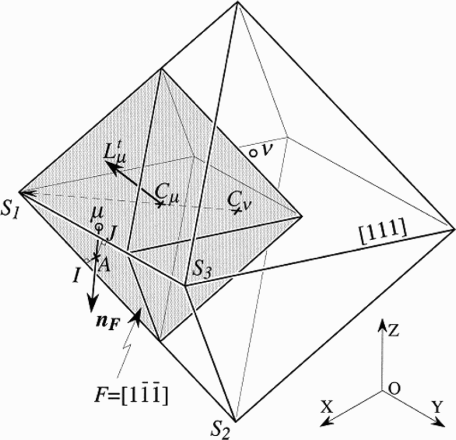
Schematic diagram of octahedron cellular growth 6
Experimental procedure and results analysis
In this study, the casting material is melted in a 200 kg vacuum induction furnace under argon protection. The composition of the high silicon steel is 6.56Si–0.0025C–0.21Mn–0.009P–0.0007S–0.96Al–0.019Cr–0.01Ni–0.01Cu–0.01V. A cuboid shape mould was designed to research the solidification structure of slab, which can directly be used for rolling, getting rid of the forging process. The mould is 20 mm material steel (see Fig. 3). Pouring temperature was 1773 K. After pouring, the mould and casting were cooled in the air. The demoulding temperature was 1473 K. The ingot size is 400 × 90 × 600 mm Fig. 4.
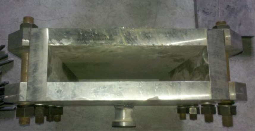
Steel mould

a ingot and b sample
The sampling location is presented in Fig. 5; the sample size is 200 × 90 × 30 mm. The alloy sample was polished and etched in 5% nitric acid. The solidification structure is shown in Fig. 6, where it is seen that the solidification structure comprises coarse crystals and a high proportion of columnar crystals, which are 12.3% in the width direction and 63.9% in the thickness direction.
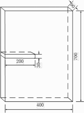
Sampling schematic
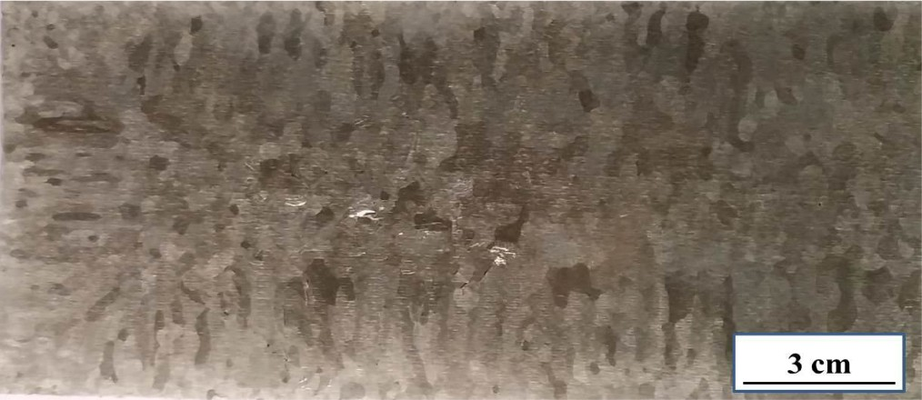
Solidification structure of ingot
The sample was cut into six small samples of 40 × 30 × 30 mm. The surface of each was polished and etched in picric acid at 343 K for 30 min. The solidification structure photographs were taken with an optical microscope with 10 times enlargement. The photomicrographs are presented in Fig. 7; coarse grains and some cracks exist at columnar crystal boundaries. The total number of grains of the six small samples was counted, and the average grain size was calculated, which is 4.48 × 10− 6 m2.
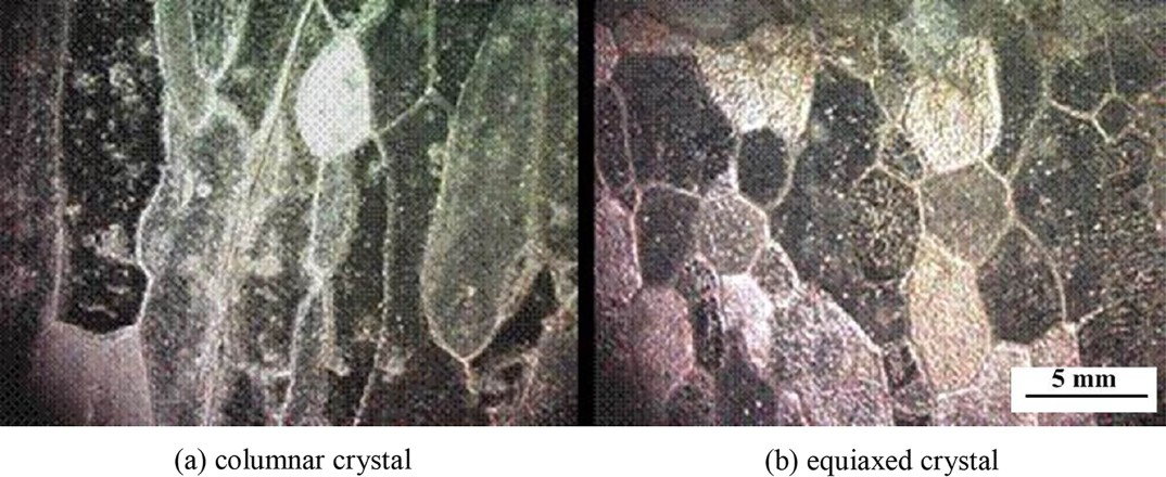
Macrostructure of a columnar crystal and b equiaxed crystal
Solidification simulation
Simulation process
Modelling and meshing
Three-dimensional model of microstructure simulation was established by Pro/E software, and it has the same dimension scale with the actual ingot. Then, the three-dimensional model was imported into the ProCAST MeshCAST module for surface and volume meshing; the meshing size of ingot and mould is 10 and 15 mm respectively. The simulated model and size parameters are shown in Fig. 8.
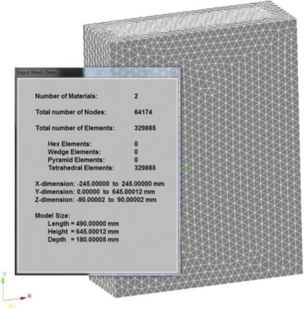
Simulation model and size parameters
Material parameters setting
The composition of high silicon steel was input to material database in the PreCAST module; Scheil model was adopted to calculate the thermal–physical parameters, such as thermal conductivity, density, enthalpy, solid fraction, etc. The liquidus and solidus temperatures were obtained through the Fe–Si phase diagram, which are 1721 and 1675 K respectively.
Initial conditions
Neglecting the filling time, the initial temperature of molten steel (the same as pouring temperature) is 1773 K, the initial temperature of mould was 353 K and ambient temperature is 318 K.
Boundary conditions
Heat transfer between mould and ambient was determined by equation (12)

Interface heat transfer between the mould and ingot was determined by equation (13)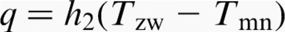
In order to study the influence of superheat on solidification microstructure of 6.5%Si steel ingot, the influence of superheat of 52, 40, 30, 20 and 10 K on the solidification structure was investigated respectively. To study the effect of cooling condition on solidification microstructure, in the case of slow cooling, the solidification structures of the ingot at superheats of 40, 30 and 20 K were also calculated. The initial temperature T 0 and interface heat transfer coefficient h 2 employed in the calculation model are listed in Table 1.
Solidification thermal parameters for M1, M2, M3, M4, M5, M6, M7 and M8
Gaussian parameters setting
Surface nucleation parameters ΔT
S,n = 0.5 K, surface nucleation undercooling for the standard deviation ΔT
S,σ = 0.1 K, volume nucleation parameters ΔT
V,n = 6.5 K and volume nucleation undercooling for the standard deviation ΔT
V,σ = 0.1 K. Maximum surface nucleation density was determined by the photomicrographs in Fig. 5; n
S,max = 3.2 × 10⁵ m− 2, according to the ASTM standard algorithm 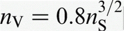
Growth kinetics parameters setting
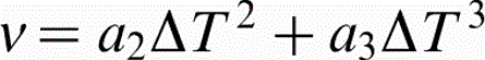
The dendrite tip growth kinetic parameters a 2 and a 3 were calculated using the data in Table 2, 15,16 as a 2 is 2.183 × 10− 7 and a 3 is 1.440 × 10− 7. Solute partition coefficient k and liquidus slope m in Table 2 were determined by the Fe–Si binary phase diagram.
Composition C 0, solute partition coefficient k, liquidus slope m and diffusion coefficient D L of binary Fe based alloy
Numerical simulation results
Comparison with experimental
The simulated result of M1 is shown in Fig. 9b where it can be seen that the microstructures are composed of columnar and equiaxed grain zones. The results are consistent with that of the practical experiment. The proportion of columnar zone is ∼12.5% in width and 66.7% in thickness; the mean surface area of the grain is ∼4.49 × 10− 6 m2.
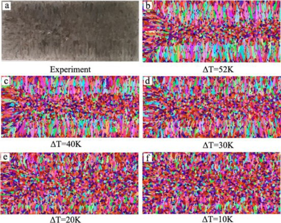
Solidification structure of simulation under different superheat
Effect of superheat on solidification microstructure
Figure 9b–f shows the solidification microstructures of M1–M5. Estimating the proportion of columnar zone in each model, the results are shown in Fig. 10 where it can be concluded that, as the superheat decreased from 52 to 10 K, the columnar zone decreased in both width and thickness. This is because that low superheat can reduce the temperature gradient in the molten steel, so as the temperature decreases, both the size and number of atom cluster in molten steel are increasing, i.e. atomic disorder degree of molten steel is decreasing, which helps to promote nucleation. Furthermore, low superheat temperature also reduces the probability of remelting of grain fragments, which fall off from the inner wall of the mould, melt from dendritic tips as well as sinking from the free surface. Therefore, low superheat is an important factor of development of nucleation embryos, which is beneficial to obtain a high equiaxed zone ratio and restrain the development of columnar crystals.
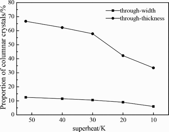
Proportion of columnar crystals of M1, M2, M3, M4 and M5
The post-processing module in ProCAST was adopted to estimate the average grain size of both columnar crystal and equiaxed crystal in each model. The statistical results in Fig. 11 show that, as the superheat temperature decreases, the average grain area of columnar crystals decreases significantly, mainly due to the decrease in temperature gradient at the solidification front, which inhibits the growth of columnar crystals. On the other hand, when the superheat decreases, the centre solidification time will increase, and the nucleation cores formed in the relatively high temperature region will have longer time to grow, which may lead to the number of grains in the central equiaxed grain zone decreasing; consequently, the average grain size of the centre equiaxial crystal increased slightly.
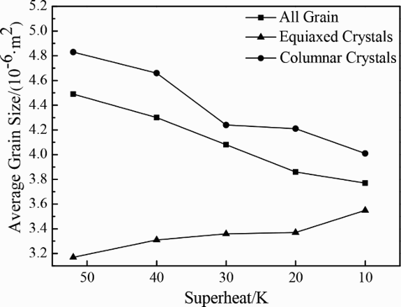
Average grain size of M1, M2, M3, M4 and M5
Effect of cooling condition on solidification microstructure and discussion
Figure 12 shows the microstructures of M2, M3 and M4 to M6, M7 and M8. Figures 13 and 14 express the proportion of columnar crystals and the average grain size of each model. It can be seen from Figs. 12–14 that the proportion of columnar crystals and the average grain size of the solidification structure of the casting under slow cooling condition are finer than those under air cooling condition at the same superheat temperature. This is because the lower heat transfer coefficient under slow cooling is an important factor in reducing the temperature gradient at the solidification front and extend the solidification time, which will help to expand the equiaxed zone and obtain a finer solidification structure.
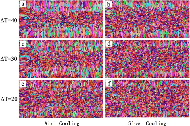
Simulated results of a M2, b M6, c M3, d M7, e M4 and f M8
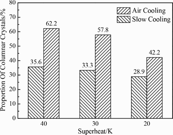
Proportion of thickness direction columnar crystals of M2, M3, M4, M6, M7 and M8
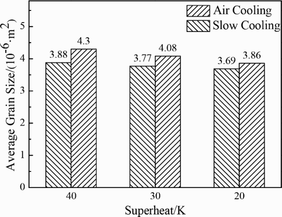
Average grain size of M2, M3, M4, M6, M7 and M8
Conclusions
1.The grain sizes of both columnar crystals and equiaxed crystals in high silicon steel are large, the mean surface area of grain being 4.48 × 10− 6 m2. The proportion of columnar crystals is 12.3% in the width direction and 63.9% in the thickness direction. 2. The CAFE method was adopted to simulate the microstructure of high silicon steel, and the simulated results included both the proportion of the columnar crystal and grain size, which is in good agreement with the experimental results; thus, the optimal simulated parameters of CAFE were determined, which are n
S,max = 3.2 × 10⁵ m− 2, n
V,max = 1.45 × 10⁸ m− 3, ΔT
S,n = 0.5 K, ΔT
V,n = 6.5 K, ΔT
S,σ = 0.1 K and ΔT
V,σ = 0.1 K. The model in this paper can be used to predict the solidification structure of high silicon steel castings. 3. For high silicon steel casting, when the superheat temperature is reduced, the columnar dendrite zone reduced, and the compactness and proportion of central equiaxed grain zone increased. Therefore, low superheat temperature is beneficial to get finer solidification structure of high silicon steel. In addition, slow cooling can help in improving the solidification structure.
Footnotes
Acknowledgements
The authors would like to acknowledge the financial support of 863 Program (grant no. 2012AA03A505) and the National Natural Science Found of China (grant no. U1360201). Sincere gratitude and appreciation should be expressed to Professor J. M. Zhang for his careful guidance.