
Abstract
This paper presents an integrated approach for SO2 reduction and energy conservation by recycling waste gas during the iron ore sintering process. We established a mathematical model for the sintering flue gas temperature (SDG-T) and SO2 content (SDG-SC), and analysed the influences of the raw materials (carbon and moisture contents) and operation parameters (sinter bed height and speed). Correspondingly, we develop a novel optimisation framework for the design of the sintering process. Using the proposed integrated approach along with a 360 m2 sinter from Anshan Iron and Steel Co., Ltd (An Steel) as an example, we have considered the SO2 captured by the waste heat resources during the sintering process. Finally, we compare our design approach with that of the conventional approach to verify the capability of our proposed approach in capturing SO2 using recycled waste gas.
Introduction
The process of iron ore sintering is not only the prime energy consumer in the iron and steel industry (ranking second only to the iron making process 1 ) but also the main source of SO2 (40–70% of the SO2 produced by the iron and steel industry is generated during the sintering process 2,3 ). The charge from the sintering process consists of a mixture of fine ores, additives (e.g. lime, olivine) and recycled iron bearing materials from downstream operations (including, but not limited to, coarse dust and sludge from blast furnace gas cleaning, mill scale) to which coke breeze is added to enable the ignition of the total charge. A large amount of high temperature flue gas (100–1500°C) 4,5 is produced during the sintering process because sulphocompounds (FeS2, CuFeS2, CuS, ZnS, PbS) and sulphates (FeS2, CuFeS2, CuS, ZnS, PbS) are widespread in mixtures of fine ore and additives, and >80% of the S element is converted into SO2 flue gas. The SO2 concentration variation is large scale (400–5000 mg Nm− 3). 6,7 Therefore, research on methods for SO2 reduction by waste heat recycling during iron ore sintering can play an important role in energy conservation and environmental protection efforts.
The utilisation and recovery of the waste gas is the primary mean for conserving energy during the iron ore sintering process. The sintering process can be divided into two steps – sintering and cooling. The waste heat resources characterising the sintering process, i.e. the sensible heat from the main exhaust gas from the sintering machine and the cooling flue gas from the sinter cooler, are generated during these two steps (Fig. 1). Waste heat recovery technology commonly used in the European Union, Japan and other countries is the emission optimised sintering system first installed at the Ijmuiden, Netherlands, plant. This technology utilises the waste gas to preheat combustion supporting air, and the energy saved accounts for ∼20% of the total sintering energy consumption. 8,9 A liner type cooler is used by the Sumitomo Metal Mining Co., Ltd (SMM), and the recoverable waste heat from cooling the flue gas accounts for ∼10% of the total sintering energy consumption. 10 Research has shown that producing 1 ton of sinter ore generates 1439.36 MJ of waste heat resources, in which the sensible heat of the sinter ore and the sintering flue gas account for 11.14 and 8.18% respectively. 11,12 Therefore, effective waste heat recovery and utilisation are important energy conservation considerations for the sintering process.
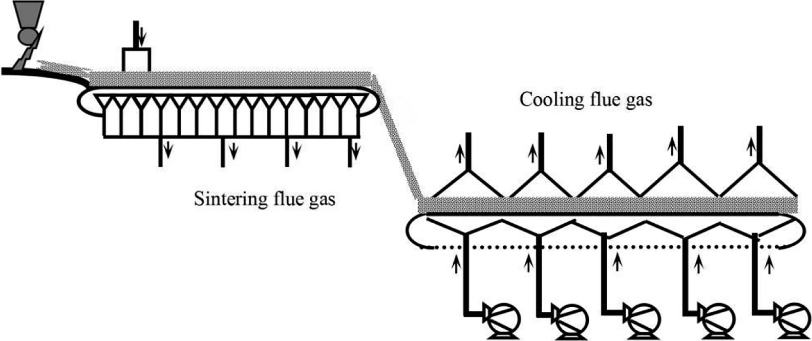
Schematic diagram of sintering process and waste heat resource
The use of low sulphur content raw materials and flue gas desulphurisation are the two methods generally used to reduce the SO2 content in flue gas. The former method, however, is limited in practice for technical and economic reasons. Thus, flue gas desulphurisation systems and technology have been widely adopted by sintering plants in recent years, including the Voeste Alpine MEROS system, 13 flue gas desulphurisation (FGD) by activated carbon by Nippon Steel 14 and the swirl jet absorbing wet limestone gypsum sintering FGD technology by Bao Steel, 15 recycling of waste gas from the end of the sinter strand combined with heat exchange (at Thyssen Krupp Stahl, Duisburg, Germany), 16 recycling of waste gas from part of the end sinter strand and use of waste gas from sinter cooler (at Voestalpine Linz, Austria), 9 etc.
Various studies on the sintering process have been conducted for different purposes. Muchi conducted one-dimensional modelling of the coke combustion and heat transfer in a sinter bed. 17 The change of coke particle size during combustion has also been considered, 18 as well as the bed height and porosity. 19,20 The discrete element method has been applied to a sintering process model. 21 To enhance the efficiency of the sintering process, proposals have been put forward with respect to oxygen supply, 22 double ignition 23 and the supply of heat from a different fuel. 24 Reducing the S content in raw materials 25,26 and flue gas circulation sintering technologies 27–30 have also been proposed. However, these studies have mainly focused on the waste heat of flue gas or SO2 behaviour in the flue gas circulation sintering processes. In our study, we propose an integrated framework for SO2 reduction by recycling waste heat during the iron ore sintering process, and we establish and verify a flue gas temperature and SO2 content distribution model in a field test. 31 We analyse the influencing factors, including bed height, bed speed, carbon content and moisture content, and discuss the distribution laws of the flue gas temperature and SO2 content. Finally, we compare results using our integrated design with those of the traditional process, using a 360 m2 sinter machine as an example. This paper presents our integrated design for waste heat recovery and SO2 reduction, a technology that will prove useful in the sintering process industry.
Methodology
Modelling method
Theoretical foundation
The sintering process takes place from the top to the bottom of the sintering bed, which may be divided into four vertical zones, i.e. the sintered, combustion, drying and wet zones. In the combustion zone, the iron ore is in full contact with the coke breeze and is burned, producing sintering flue gas (1300–1500°C). At this stage, the unburned iron ore temperature increases due to the passage of the high temperature sintering flue gas, and a flue gas temperature in the drying zone of 100–700°C is typical. After the drying zone is the wet zone, where the flue gas temperature is no more than 100°C. After full combustion between the iron ore and coke breeze, the flue gas temperature in the sintered zone is generally < 1100°C. Governing equations have been established based on the four vertical zones shown in Fig. 2a .
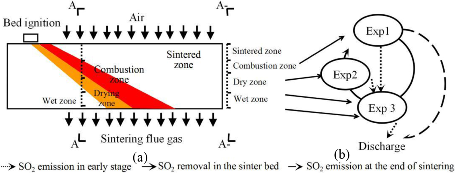
Schematic diagram of a zone structures and b SO2 enrichment emission model across sinter bed
The S element in the sinter mixtures mainly exists in the form of sulphide (FeS2, BaSO4, etc.). SO2 is mainly produced during three stages of the sintering process, 32,33 namely, the combustion stage (Exp. 1), diffusion stage (Exp. 2), and absorption stage (Exp. 3), as illustrated in Fig. 2b .
Assumptions
We have made simplifying assumptions to describe the flue gas temperature and SO2 content mathematical model. These assumptions are described in detail below: (i) we simplified the sinter bed to a one-dimensional area in the direction of the bed length and assumed the material properties to be homogeneous in the sinter bed. We did not consider changes in the properties across the width of the bed (ii) we assumed the walls of the sinter bed to be heat insulated. We ignored heat loss, air leakage, mass transfer and radiation heat transfer. We simplified the combustion model of powdered carbon using the internal heat source model
34
(iii) we ignored the adsorption capacity of the sinter ore and the internal diffusion of the sinter mixtures.
Governing equations
Based on the assumptions above, we considered all the physical and chemical changes of the gas and solid phases in the sintering process. The equations for the processes occurring in each sintering zone are detailed below. Table 1 lists all notations.
(1) Sintered zone
Nomenclature used in equations
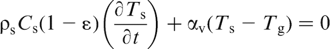
Gas phase energy conservation (2) Combustion zone (3) Drying zone (4) Wet zone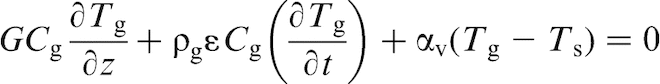
Gas phase energy conservation: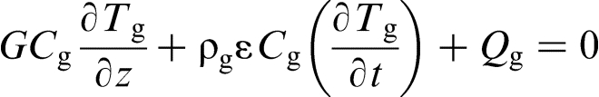
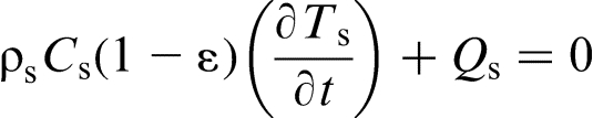
Gas phase energy conservation

The gas and solid phase energy conservation equations are the same for this zone as those for the drying zone.
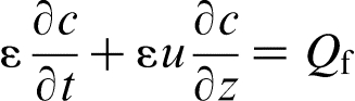
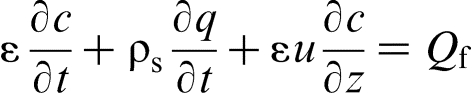
SO2 content equation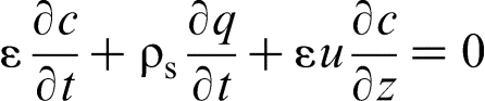
Model solution
To ensure accuracy, we changed the governing equations into discrete equations using the explicit difference scheme. We meshed the sinter bed into 400 × 2400 volume elements and used Visual Basic programming language for the model calculations. A schematic diagram of the calculation process may be found in Appendix 1.
Model validation
To validate the model's accuracy, we compared its results with those from the measured data. Table 2 shows some parameters of the field data from Anshan Iron and Steel Co., Ltd (An Steel).
Some parameters of field data from An steel
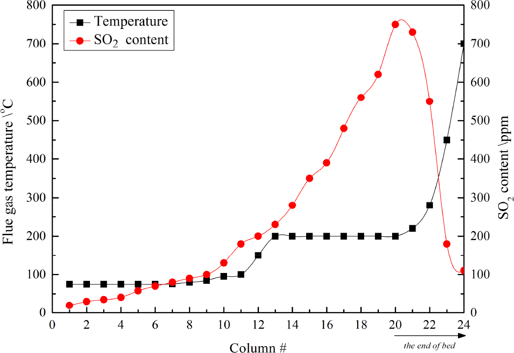
Figure 3 compares the calculated and measured values for flue gas temperature and SO2 content, and we see that the overall model trends accord with the practical conditions. The relative errors for the flue gas temperature and SO2 content are < 10%, because we ignored air leakage, simplified the boundary conditions and made other assumptions as mentioned above. A comparison of the results shows that the model can basically reflect the laws followed by the flue gas temperature and SO2 content in the sintering process.
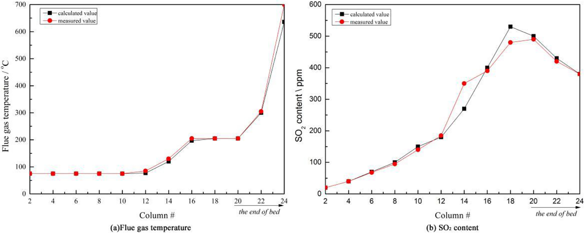
Comparison of calculated and measured values: a flue gas temperature, b SO2 content
Effects of operation and raw materials parameters
We next investigate the influences of operational parameters (sinter bed height and speed) and the raw materials used (the carbon and moisture contents). According to the distributions of SFG-T and SFG-SC, the results show that the SFG-T consists of three stages, namely the constant and low temperature stage, the constant and medium temperature and the rapid rising stage, likewise for SFG-SC, the slow rising stage, the rapid rising stage and fast falling stage.
Effect of sinter bed height
Sinter bed height is an important parameter that influences SFG-T and SFG-SC. We conduct computational tests for varying sinter bed heights from 600 to 800 mm, and the results are shown in Fig. 4.
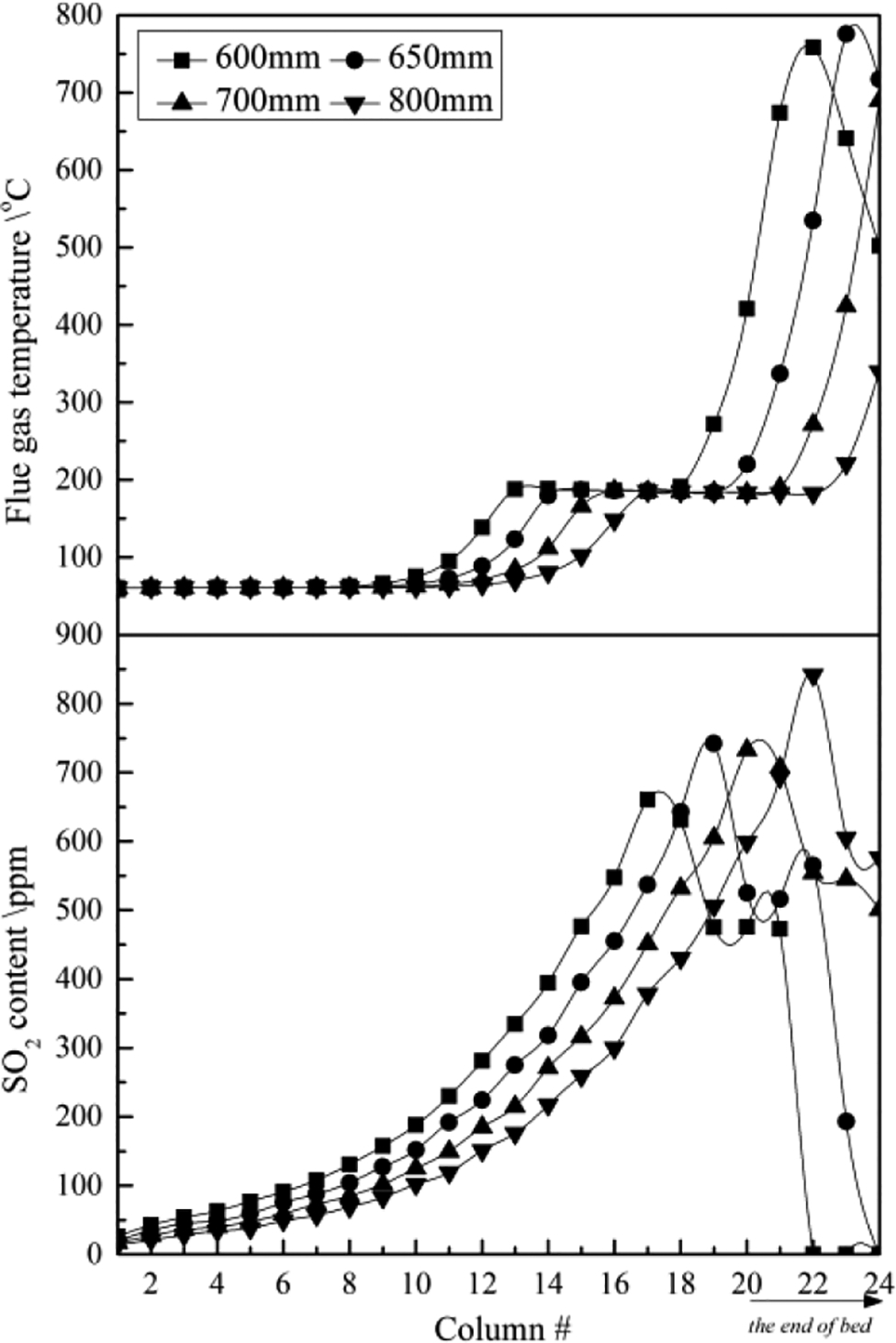
Effect of sinter bed height
Sinter bed height variations affect the SFG-T slightly in the first 10 columns, but the SFG-T increases rapidly in the middle columns (10 to 22) by two step changes. However, SFG-T decreases sharply for sinter bed heights < 650 mm. The SFG-T increases with a decrease in sinter bed height in the same place. When the sinter bed height is higher than 700 mm, the sinter mixtures under burn.
The SFG-SC continuously rises during most of the process. However, the SFG-SC declines significantly toward the end of the columns, indicating that all the S in the sinter mixtures transform into SO2 when the sinter bed height is < 650 mm.
Effect of sinter bed speed
Given that we assume the sinter bed to be fixed, we use the diffusion rate of the flue gas in the moving direction as the bed speed. We then investigate the influence of sinter bed speed variations on the SFG-T and SFG-SC (Fig. 5).
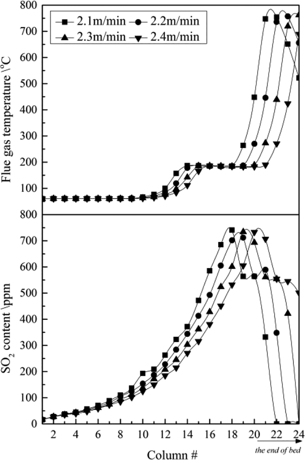
Effect of sinter bed speed
We find that a low sinter bed speed produces high SFG-T and SFG-SC values in the rising process because the flue gas stays in the sintering process for a long period of time at a low speed when the distance is constant. However, when the speed is 2.2 m min− 1 or slower, the SFG-T passes the burn through point, and the SFG-T and SFG-SC values then drop sharply. When the speed is 2.3 m min− 1 or faster, the SFG-T and SFG-SC continues to increase first and then decrease at the end of the sinter bed.
Effect of carbon content
Carbon content plays a significant role in the sintering process. We next study carbon content variations from 2.6 to 3.2% while holding the bed speed, height and other parameters constant.
The results shown in Fig. 6 reveal that carbon content obviously affects the flue gas temperature at the end of the sinter bed. The SFG-T generally increases with increasing carbon content. However, when carbon content is 2.6% or lower, the flue gas temperature remains at a constant value instead of rising because of the low carbon content, which cannot provide enough energy for the sintering process. When the carbon content is 3.0% or higher, then SFG-SC peak appears early. There is no SO2 present at the end of the sinter bed because of the fast sintering speed and high carbon content.
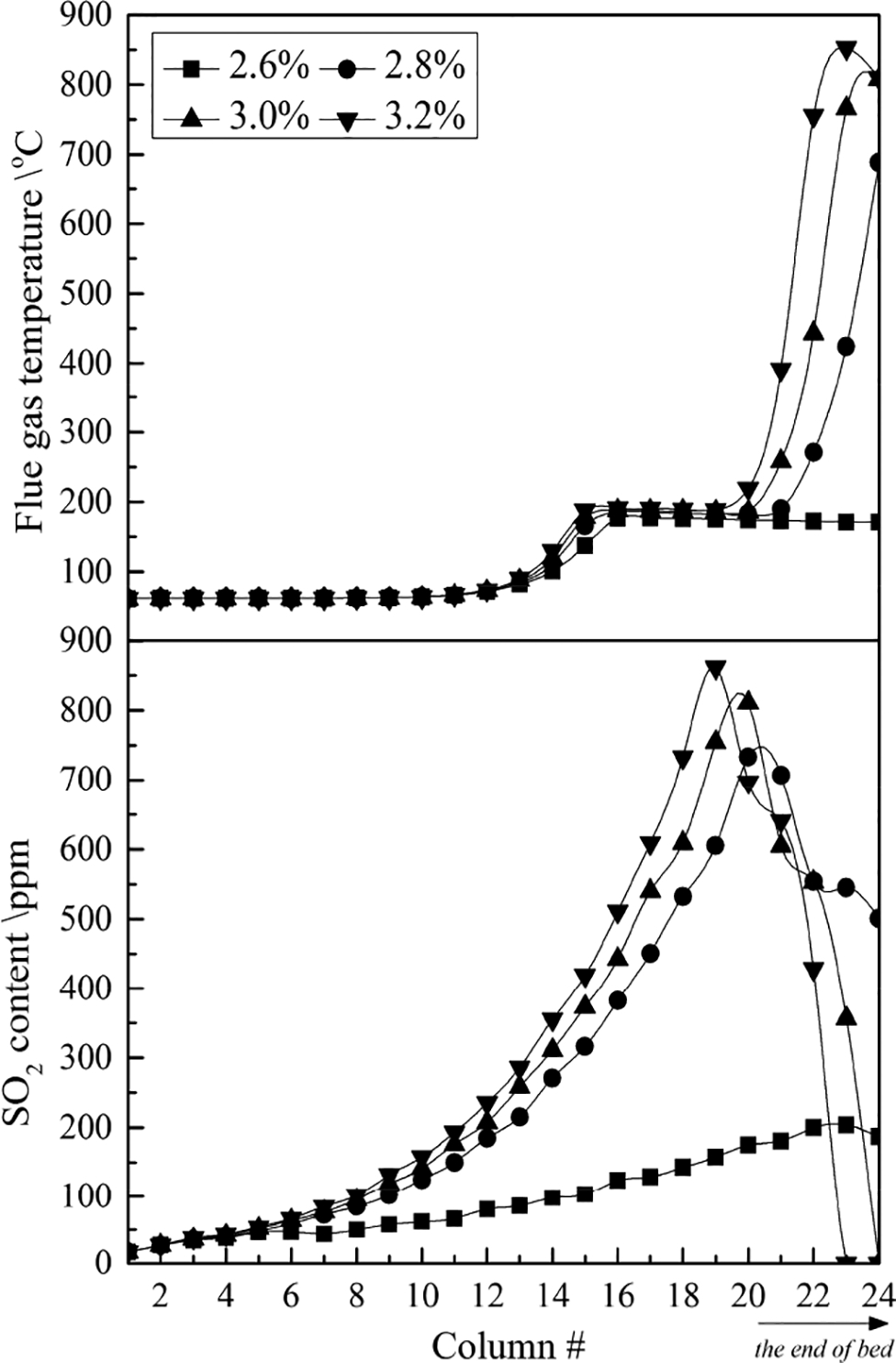
Effect of carbon content
Effect of moisture content
Moisture content is an important physical parameter for sinter mixtures. We next study the moisture content variations from 5 to 8% while holding the bed speed, height and other parameters constant.
Figure 7 shows that the SFG-T increases with increased moisture content at the front of the sinter bed and with decreased moisture content at the end of the sinter bed. We attribute this increase to the fact that, initially, a high moisture content is restrictive for SFG-T increase, but after the water has been removed half way along the sinter bed, the SFG-T reaches its maximum level in the area of hot zone burn through point. Meanwhile, the SFG-SC increases as the moisture content decreases in the rising stage, due to fact that the absorption level of the sinter mixtures increases with increased moisture content. At the end of the sinter bed, given that a minimal moisture content is beneficial for the sintering process, the SFG-SC content is low with minimal moisture content.
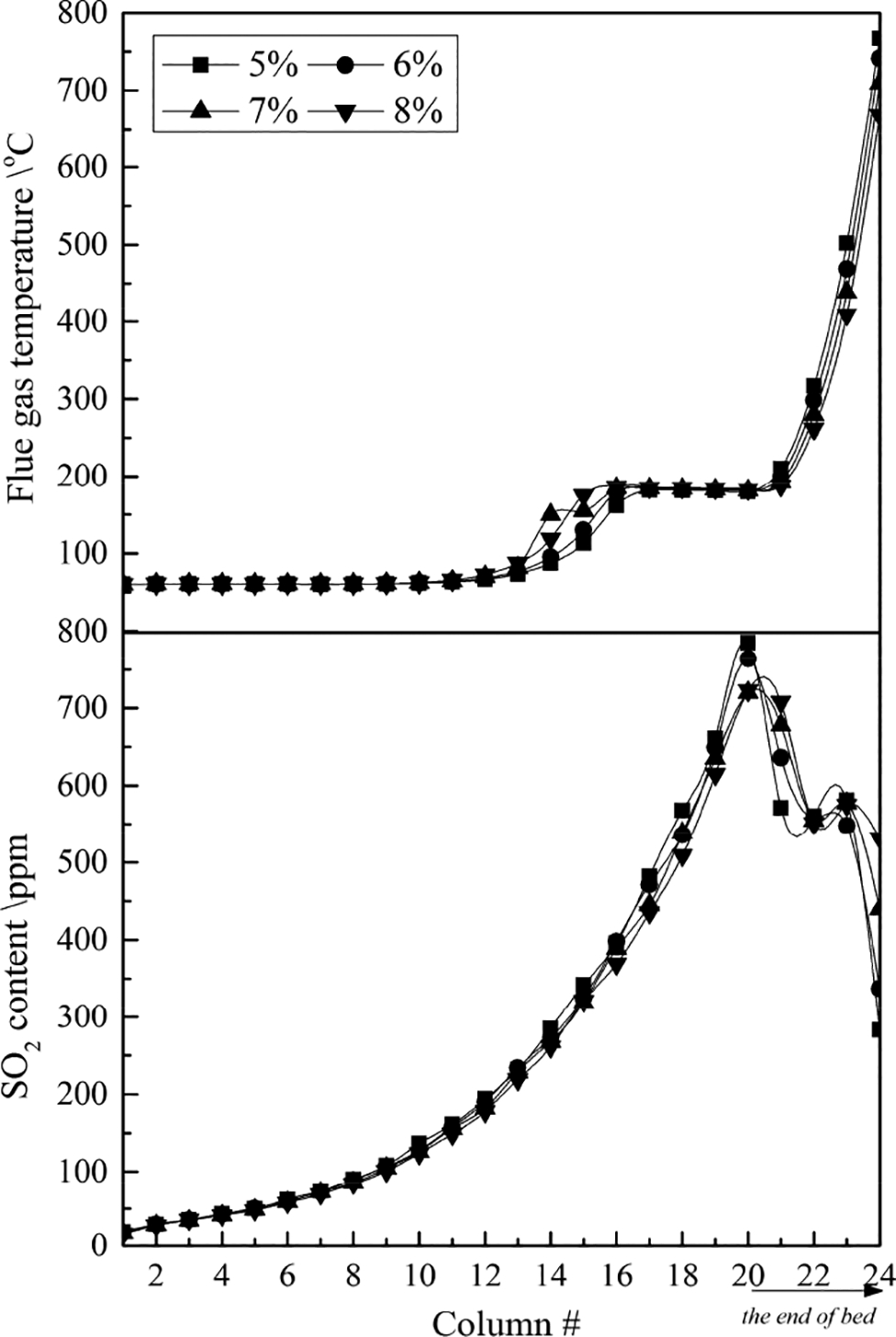
Effect of moisture content
Case study
Basic information
For our case study, we use one sinter and one cooler in An Steel's No. 3 sintering plant. The sinter is a draper type with air draft, and the cooler is a cooling type with forced draft. The annual sinter ore output of this plant is 391.3 × 10⁴ t/a. The flowrate of the plant's induced draft fan is 990 000 Nm3 h− 1. The delivery of each fan is 4.2 × 10⁴ m3 h− 1. The main parameters in the case study are listed in Table 3.
Properties of case states
In An Steel's conventional sintering process, as shown in Fig. 8, all sintering flue gases are discharged after desulphurisation by the dedusting equipment (the rotary spray drying FGD technology). We divide the cooling flue gas from the cooler into five sections, as detailed in Table 4. The first and second sections are used to generate steam in the waste heat boiler, whereas the other cooling sections discharge flue gas directly.
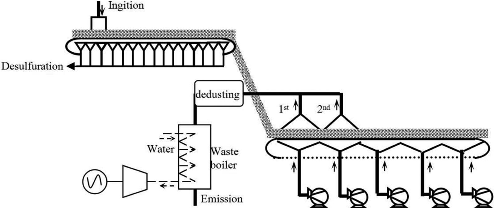
Diagram of sintering waste heat recovery, utilisation and desulphurisation using conventional approach
Cooling flue gas parameters of case study cooler
SFG-T and SFG-SC in case study
Using this basic information from the An Steel sintering plant (Table 3), we can then load the information into the model and calculate the SFG-T and SFG-SC values in the four zones. Table 5 and Fig. 9 show our results from these SFG-T and SFG-SC calculations and SFG partition.
SFG partition based on model calculations in case study
SFG-T and SFG-SC values in case study
Integrated design used in case study
Waste heat resources may be utilised in one of three ways, i.e. preheating and drying (D1), ignition and combustion supporting (D2) and hot air sintering (D3). The demands of these three methods are detailed in Table 6.
Requirements of different direct waste heat utilisation methods
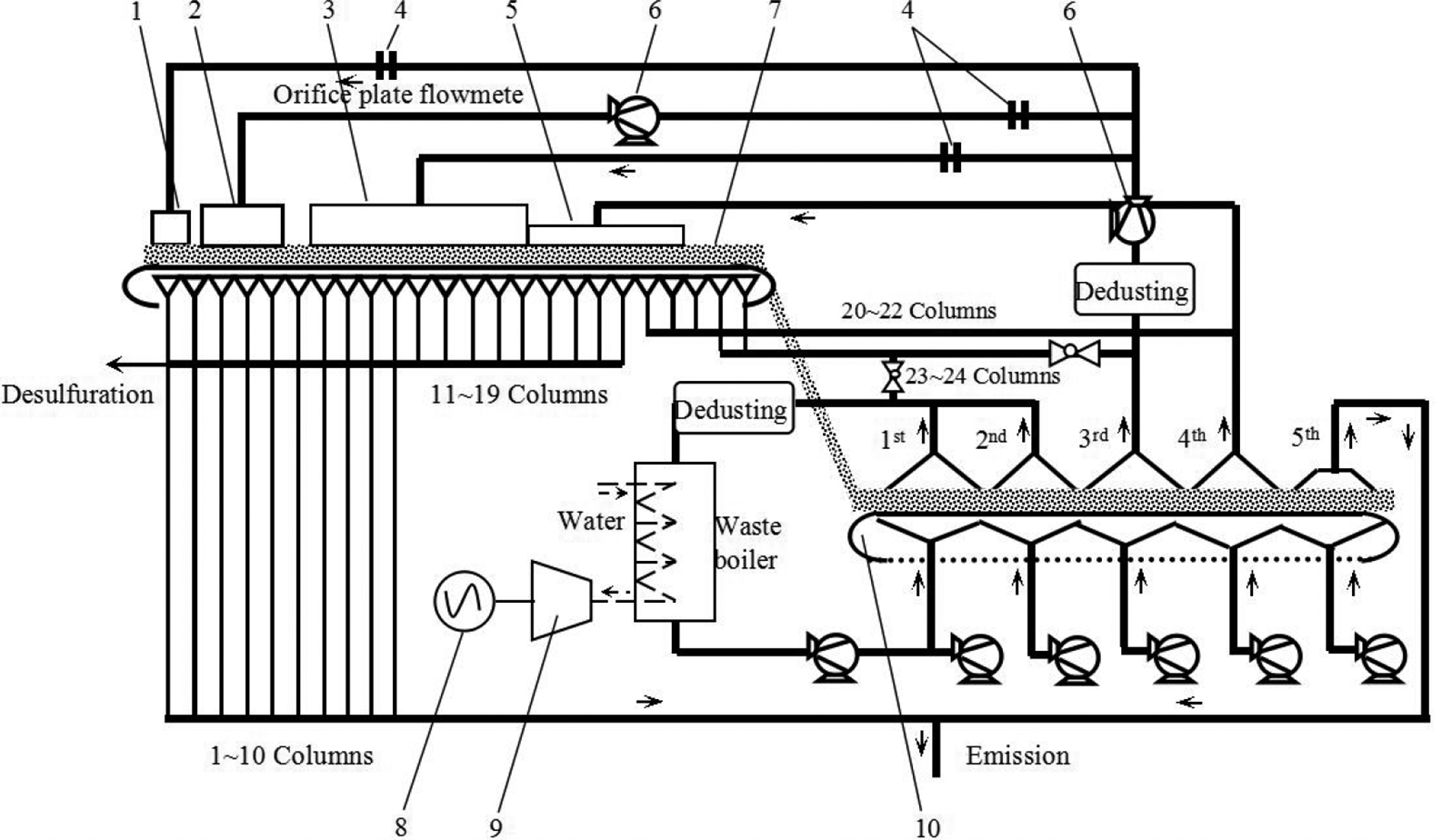
Figure 10 shows the details of our proposed integrated design. The primary methods used in the integrated design of the case study are as follows: (i) cooling flue gas with a high temperature and minimal particulate matter from the C-1 and C-2 is used to generate steam (∼70 × 104 to 90 × 104 Nm3 h− 1) in the waste heat boiler (ii) approximately 10% of the cooling flue gas from the C-3 (∼3.5 × 10⁴ to 4.5 × 10⁴ m3N h− 1) is used for D2 (iii) sintering flue gas with a high temperature from S-4 (∼8 × 10⁴ Nm3 h− 1) is mixed with the remaining 90% of the cooling flue gas from C-3 (∼30 × 104 to 40 × 104 m3N h− 1, 250°C) and then used for D1 and D3 (iv) cooling flue gas from C-4 (∼25 × 104 to 30 × 104 m3N h− 1) is mixed with the sintering flue gas from S-3 (∼12 × 104 m3N h− 1) and used for D3 (v) the sintering flue gas from S-1 is mixed with C-5 cooling flue gas, which ensures that the mixed flue gas temperature is higher than the dew point corrosion temperature. The mixed flue gas may be discharged before aspiration (vi) the sintering flue gas from S-2 is discharged after desulphurisation and aspiration (vii) to ensure safe and stable running of the waste heat boiler, the sintering flue gas from S-4 is connected with the cooling flue gas from C-1 and C-2. When cooling flue gas fluctuations occur, the sintering flue gas may be used for supplementation. 1. Preheater, 2. igniter, 3. sinter table board, 4. flowmeter, 5. flue gas mask, 6. air blower, 7. iron ore, 8. generator unit, 9. steam turbine, 10. sinter cooler.
Comparisons with the conventional approach
Compared with the conventional sintering process, our integrated design is more efficient. Our calculations show that if flue gas (18 × 104 Nm3 h− 1, 200°C) is used in D1, a reduction in ∼0.45 kg solid fuel per ton ore could be realised. If flue gas (34 × 104 Nm3 h− 1, 220°C) is used for D3, a reduction in ∼3.2 kg solid fuel per ton ore could be realised. If flue gas (3.93 × 10⁴ Nm3 h− 1, 230°C) is used for D2, a reduction in ∼11.7% of the gas could be realised. For an investment cost of 50 RMB/(m3 h− 1) to 75 RMB/(m3 h− 1), and a running cost of 1.0 RMB/(m3 h− 1) to 1.5 RMB/(km3 h− 1), and if the sintering flue gas from only the S-2 section is processed by the desulphurisation equipment, a reduction of 40 × 104 to 60 × 104 Nm3 h− 1 of flue gas could be realised. Moreover, 27.3 million RMB in investment costs and 5.5 million RMB in running costs could be saved. Based on An Steel's annual sinter ore output of 391.3 × 10⁴ t/a, this represents a solid fuel reduction in 14 283.5 t and a gas reduction in 2264.8 × 104 Nm3.
Conclusions
Based on the information provided above, our main conclusions are as follows.
1. In the moving direction, SFG-T consists of three stages, namely the constant and low temperature stage, the constant and medium temperature and the rapid rising stage. Likewise, for SFG-SC, the slow rising stage, the rapid rising stage and the fast falling stage.
2. SFG-T and SFG-SC values are influenced by many factors, including the characteristics of the raw materials (the carbon and moisture contents) and the operating parameters (sinter bed height and speed). The SFG-T and SFG-SC values increase with increasing carbon content, and decrease with bed height, bed speed and moisture content. Furthermore, the SFG-SC value peaks appear earlier than those of SFG-T when other factors are held constant.
3. Compared with the conventional process, our integrated design process saves 27.3 million RMB in initial investment costs and 5.5 million RMB/a in operating costs, while also achieving a 14 283.5 t/a reduction in solid fuels and a 2264.8 × 104 Nm3/a reduction in gas.
Acknowledgements
The authors wish to thank An Steel, China for supplying the sinter mixture. The research was supported by the National Natural Science Foundation of China (grant no. 51274065) and the Science and Technology Project of Liaoning Province (no. 2013020191-301).
Footnotes
Appendix 1. Flow diagram of flue gas temperature and SO 2 content calculation