
Abstract
Based on the developed coupled model of electromagnetism, heat and solute transportation, the macrosegregation formation and effect of secondary cooling water ratio on macrosegregation degree in strand during round bloom continuous casting process have been investigated. The solute segregation degree fluctuates from a positive to a negative value with distance from strand surface in the initial solidified shell region within thickness of 20 mm. A negative segregation region in concave shape and an irregular positive segregation zone are presented in the fixed and loosened side of strand respectively due to the gravity and thermosolutal convection. As the secondary cooling water ratio decreases from 0.25 to 0.15 L kg− 1, the solidification ratio at final electromagnetic stirring (F-EMS) centre increases from 73.14 to 77.83%. For the steel grade of 50Mn casted by round bloom casting within diameter of 0.35 m, the optimal solidification ratio at F-EMS centre is 75.05%, where the radial centre crack and shrinkage cavity at strand cross-section are removed.
Introduction
The compositional non-uniformity at the macroscopic level of a casting, which is so called macrosegregation, is one of the most well known and classical problems during the continuous casting (CC) process. Such segregation will result in the heterogeneity of physical and mechanical properties throughout the whole casting, preventing its products to perform as expected in the specific application, which is due to the fact that complete elimination of macrosegregation in subsequent hot working process is very difficult. 1,2 Therefore, an in-depth understanding of macrosegregation formation and its control techniques for CC process is significant to improve the internal quality of castings and their products.
For the efficiency limitation of plant trial to the complex metallurgical behaviours in CC process, numerical simulation has been widely developed and used as an effective means to investigate the formation and control techniques of macrosegregation during solidification. 3,4 Compared with ingot and directional casting processes, 5,6 however, fewer researches 7,8 were reported to reveal the macrosegregation formation in the CC strand using numerical simulation. The main reason should be contributed to the redundant calculation, where model computational domain for CC system should involve the region ranged from meniscus to crater end. 9 To improve the calculation efficiency, two-dimensional (2D) 10,11 or three-dimensional (3D) model 12 ignoring the turbulent flow and its effect on the heat and solute transport in strand upper part has been adopted for the CC process. However, these may influence the model accuracy and even lead to wrong decision.
Thus, in this study, the developed coupled model of electromagnetism, turbulent fluid flow, heat and solute transport using the 3D plus 2D hybrid modelling method, which has been validated and proved to be suited for popular CC process, 9,13 was employed. Combined with the numerical simulation results, the evolution and characteristics of macroscopic transportation and the effect of secondary cooling water ratio on the macrosegregation degree during the round bloom CC process will be discussed based on plant trials at a three-strand curved round bloom caster equipped with final electromagnetic stirring (F-EMS).
Model description
Figure 1 gives calculation procedure for the multiphysics/scale mathematical coupled model. Detailed implementation procedure of the model is that the heat and solute distributions in CC strand calculated by macroscopic transport model are used as input parameters for microsegregation model first, and then, the results, including concentration field at solidification front, liquid fraction and characteristic of dendritic structure within mushy zone obtained from the microsegregation model, are returned to the macroscopic transport model to update fluid flow, temperature and solute field in the CC strand. The specific mathematical description and boundary condition for the coupled model can be found in Ref. 9. Among these, the phenomena of fluid flow, heat and solute transport in CC process are simulated by the computational fluid dynamics code Fluent, while the electromagnetism is calculated via the finite element code ANSYS. Moreover, the data of electromagnetic force are imported into the Fluent code as momentum source term through coordinate interpolation algorithm.
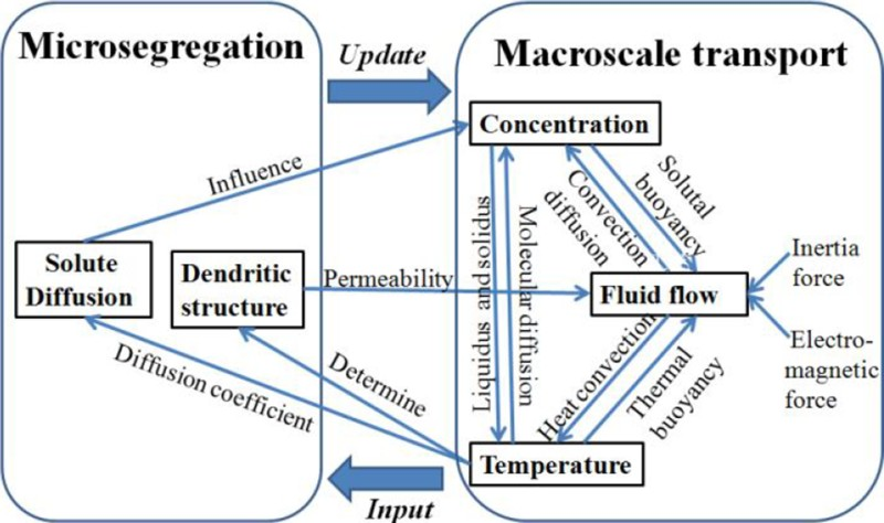
Calculation procedure for multiphysics/scale mathematical model
To improve computational efficiency, Fig. 2 gives the computational domain division for the coupled model according to the characteristic of macroscopic transportation in CC strand. It is seen that the entire computational domain for CC system is divided into three main regions: 3D turbulent flow region, 2D natural convection region and a 3D forced convection region, where the 3D–2D hybrid method was adopted to transmit the data, such as velocities, temperatures and concentrations, at the interface between the 3D and 2D calculated regions.
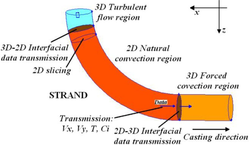
Computational domain division of coupled model for CC process
Operation conditions of industry test
Table 1 gives the operation conditions of casting test. It is seen that F-EMS is the main means to control casting macrosegregation in this curved three-strand round bloom caster. The chemical composition of the given steel is 50Mn–0.48C–0.22Si–0.80Mn–0.02P–0.02S (wt-%), and the length and cooling water flowrate of each cooling loop in secondary cooling zone adopted in plant trial are listed in Table 2 .
Operation conditions of casting test
Length and cooling water flowrate of each cooling loop in secondary cooling zone
Model results and validation
Turbulent zone
Figure 3 gives melt flow pattern and mass fraction distribution of C at strand radial longitudinal profile (x = 0 m) in the turbulent zone. It is seen from Fig. 3a that the superheated molten steel, supplied by the normal straight nozzle, passes straight down within speed of ∼0.7 m s− 1 into the CC mould, and then, part of jet flow goes down into the depth of the liquid pool, while the other part flows turn upward with a decayed speed approaching to solidifying shell and form a circulation at the upper part of the strand. For solute distribution, it is observed that the positive and negative segregation zones are presented ahead the solidification front near meniscus and in the region ranging from 0.25 to 0.75 m distance from meniscus respectively. Under the situation above, it is seen that the positive segregation is formed in the initial solidification shell, while the negative segregation begins to emerge in the shell within thickness of ∼9 mm as solidification proceeds. Combined with the melt flow pattern shown in Fig. 3a , it can be concluded that the formations of positive and negative segregation zones are induced by the floatation of solute richer molten steel with lower density and the ‘solute washing effect’ 14 of circulation flow at strand upper part respectively.
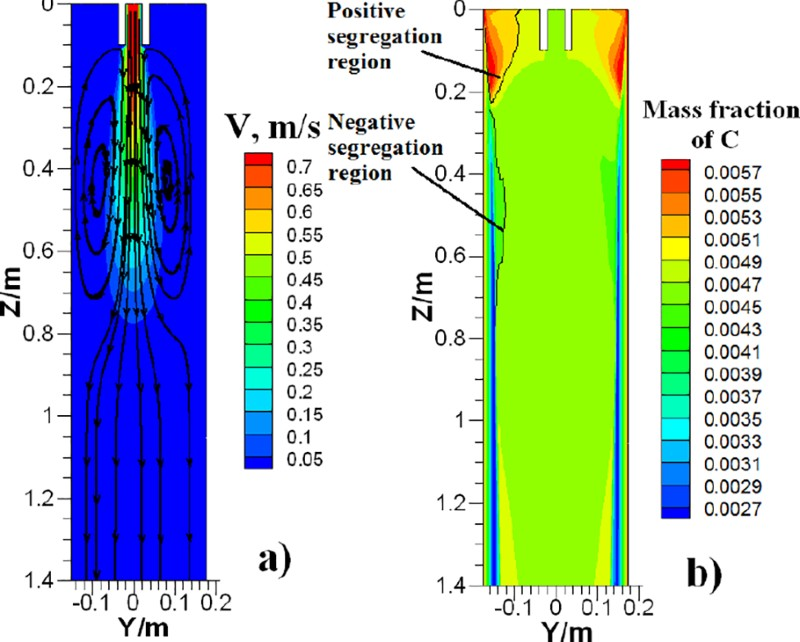
a melt flow pattern and b mass fraction distribution of solute element C at strand radial longitudinal section in turbulent zone
Natural convection zone
Figure 4 displays the melt flow patterns and mass fraction distributions of C at strand cross-sections with different distances (Z = 2, 6 and 10 m) from meniscus in the natural convection zone. It is seen from Fig. 4a that the maximum melt velocity in x and y components V x,y at strand cross-section is reduced from 0.015 to 0.004 m s− 1 with increasing distance from meniscus. Under the action of gravity, two symmetric circulations are presented at the centre area of strand cross-section. For solute distribution, it is observed from Fig. 4b that a negative segregation band within annular shape, formed in the turbulent zone, is displayed at strand cross-section due to the information heredity in the CC system. Moreover, a negative segregation region in concave shape and an irregular positive segregation zone are formed at the fixed and loosened sides of the shell respectively due to the role of thermosolutal convection and gravity.
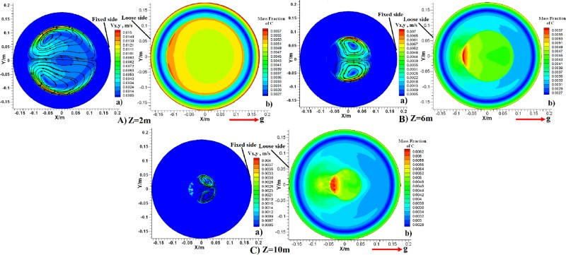
a melt flow patterns and b mass fraction distributions of solute element C at strand cross-sections with different distances from meniscus
Forced convection zone
Figure 5 shows the melt flow pattern and mass fraction distribution of C at the strand radial longitudinal section (x = 0 m). It is seen that effective horizontal swirling flow is formed at the strand cross-section in F-EMS workspace. Owing to the stirring effect, distribution of solute richer molten steel at the strand centre region gradually becomes uniform, where the maximum mass fraction of C in liquid pool is decreased from 0.62 to 0.53%.
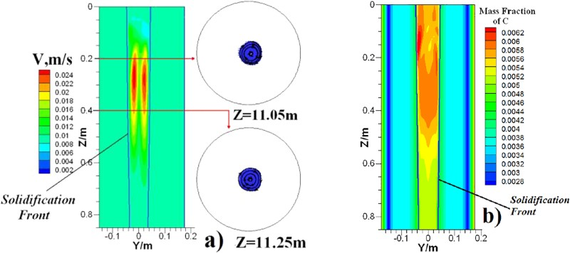
a melt flow patterns and b mass fraction distributions of C on radial longitudinal section of strand
Model validation
Figure 6 lists the detailed sample drilling locations at round bloom cross-section, where the drilling samples were obtained using a 4-mm drill in diameter up to a depth of 10 mm, and mass fractions of chemical elements C and S at the round bloom section were measured by the LECO carbon and sulphur analyser.
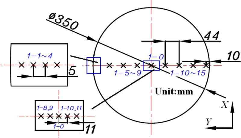
Locations of drilling samples at cross-section of bloom round casting
Figure 7 displays the comparisons between the measured results and predicted segregation profiles of C and S, defined as equation (1), at the X and Y axes of computational domain. It is seen that the measured segregation degrees of C and S at the strand centre are larger than that of the simulated results, which should be attributed to the fact that the effects of solidification shrinkage and strand deformation on solute transportation were ignored in this coupled model. However, the predicted segregation profiles of C and S presented in W shape at strand radial direction shows a good agreement with that of the measured ones. Moreover, the measured segregation degrees of C and S at sampling locations of 1-7–15 are in the range between the predicted values at X and Y axes of computational domain. Furthermore, the predicted variation that segregation degrees of C and S fluctuate from positive to negative value with distance from strand surface in the region of initial solidification shell within thickness of 20 mm agrees fairly well with that of the measured ones at the sampling locations of 1-1–4, which can also be found from the reports of El-Bealy and Fredriksson
15
and Rogberg.
16

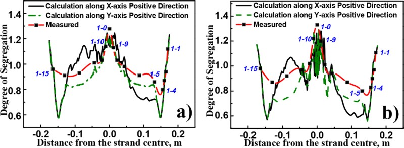
Comparison between radial measured results and predicted segregation profiles of solute elements a C and b S at X and Y axes of computational domain
Figure 8 gives the liquid fraction distribution at strand cross-section near the crater end and its corresponding casting morphology. It is seen that, under the given casting condition, the radial discontinuous non-frozen band, which will lead to the radial centre crack at casting cross-section as shown in Fig. 8b , is presented. Combined with the results shown in Fig. 7, it is observed that changed melt liquidus temperature induced by the fluctuant solute distribution in radial direction of strand is the main reason leading to formation of the non-frozen band even under the same thermal condition during the final solidification stage. 9
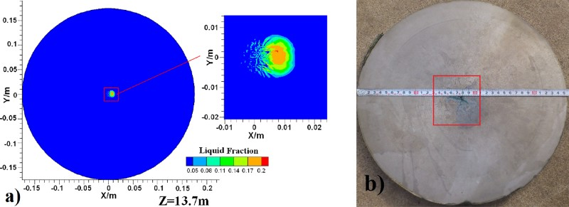
a liquid fraction distribution at strand cross-section near crater end and b its corresponding casting morphology
Model application
To prevent the radial centre crack shown in Fig. 8, the solidification ratio (ratio between the local shell thickness and casting radius R s) at F-EMS centre is optimised by varying the water ratios of secondary cooling, where casting speed is fixed to meet the constant casting period. Table 3 lists the relationship between secondary cooling water ratio and solidification ratio at F-EMS centre based on the coupled model, where casting superheat degree within 25 K is adopted. It is observed that the solidification ratio at F-EMS centre increases from 73.14 to 77.83%, while the water ratio decreases from 0.25 to 0.15 L kg− 1.
Relationship between secondary cooling water ratio and solidification ratio at F-EMS centre
Figure 9 displays the radial solute distributions of C at F-EMS exit and crater end under different water ratios. For the F-EMS exit, it is seen that an even solute distribution is presented in the liquid pool due to the action of stirring effect. The maximum segregation degree at casting centre area is reduced from 1.11 to 1.02 with decreasing water ratio, which should be attributed to the improving stirring effect induced by increasing liquid pool thickness at F-EMS working zone. 17
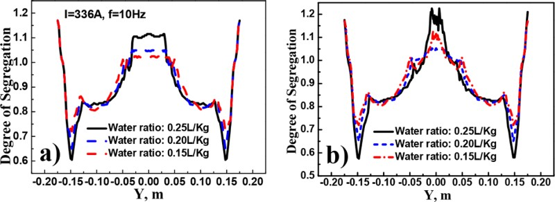
Radial solute distributions of C at a F-EMS working zone exit and b caster end under different secondary cooling water ratios
For the crater end, it is shown that the fluctuant and convex segregation distributions appear at the casting centre region under the cases of secondary cooling water ratios adopting 0.25 and 0.15 L kg− 1, which is induced by the insufficient melt stir in the F-EMS work region and the longer metallurgical length 18 as compared to the casting case with 0.20 L kg− 1 respectively. Moreover, it is observed that the lowest casting centre segregation degree is 1.05 under the case of 0.20 L kg− 1.
Figure 10 shows the morphologies of casting cross-section under different secondary cooling water ratios, where pouring superheat degrees were controlled in the range from 20 to 30 K during the whole casting period. It is observed that, as compared to the cases of 0.25 and 0.15 L kg− 1, the round bloom casting soundness has been improved remarkably under the case of 0.20 L kg− 1, where the radial centre crack and shrinkage cavity at casting cross-section are removed.
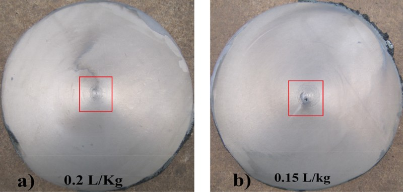
a 0.20 L kg− 1; b 0.15 L kg− 1Morphologies of casting cross-section under different secondary cooling water ratios
Based on the results above, the agreement between the simulated and trial results is fairly good. The optimal solidification ratio is 75.05% for the steel grade of 50Mn casted by the round bloom casting within a diameter of 0.35 m.
Conclusions
Based on the developed coupled model and plant trials, the formation and control of macrosegregation in strand for round bloom CC process have been investigated. The main conclusions are summarised as follows. The phenomenon that segregation degree of solute element C varies from a positive to negative value with increasing distance from strand surface is presented in the region of initial solidification shell within thickness of 20 mm. Under the effect of two symmetrical circulation flow induced by the thermosolutal convection in natural convection zone, a negative segregation region in concave shape and an irregular positive segregation zone are formed at the fixed and loosened sides of strand respectively. For the given casting case, as secondary cooling water ratio decreases from 0.25 to 0.15 L kg− 1, the solidification ratio at the F-EMS centre increases from 73.14 to 77.83%. The optimal solidification ratio at the F-EMS centre for the steel grade of 50Mn casted by round bloom casting within a diameter of 0.35 m is 75.05%, where the radial centre crack and shrinkage cavity at casting cross-section is removed.
Footnotes
Acknowledgements
This study was supported by the China Postdoctoral Science Foundation (grant no. 2014M562176).