
Abstract
To investigate the technology of twin rollers rotary forging of spiral bevel gears, three different models, which are the open die, the closed die and the floating die model, were designed to rotary forge a big spiral bevel gear whose external diameter is 246 mm. The effects of the spiral bevel gears that formed in the three models were analysed by three-dimensional finite element method under the commercial software DEFORM 3D. Finally, experiments have been carried out on a 20CrMnTi gear billet to compare the numerical results. The simulation results are in good agreement with the experimental ones and demonstrate that the floating die is the optimal model to rotary forge the spiral bevel gear, the microstructure of the gear that formed by rotary forging is refined well, and the microhardness reaches 457.8 HV (an increase of 110.0 HV) compared with the gear that formed by machining. These results provided a scientific basis for actual production of the spiral bevel gear.
Introduction
As basic transmission parts, spiral bevel gears play an important role in automobile, shipbuilding and other machinery industries because of the advantages of smooth drive, low noise and high carrying capacity. 1,2 When adopting conventional methods for machining spiral bevel gears, great deforming force is required and the actual percentage of material utilisation is low. In addition, the machining process will damage the metal's fibrous structure and result in a low anti-fatigue strength, which will reduce the service life of spiral bevel gears. 3,4
The technology of twin rollers rotary forging of spiral bevel gears is a continuous local pressure plastic forming technology. During the rotary forging process, the position of joint force of twin rollers is not changed and coincides with the axis line of machine. The twin rollers rotary forging offers the following advantages: labor saving, energy saving, materials saving, the quasi-static pressure processing, and low vibration and noise. 5,6 Since the metal's fibrous structure of tooth profile is along the streamline distribution as well as machining aggrandisement during the process of rotary forging, their bending fatigue strength, contact fatigue strength and impact resistance are significantly higher than those of the cutting parts, which can greatly improve the mechanical properties and service life of spiral bevel gears. 7
The principle of twin rollers rotary forging of spiral bevel gears is illustrated schematically in Fig. 1. 8,9 The twin rollers are installed symmetrically on both sides of the spindle axis of the device, and the angle between the roller's axis of rotation and the device's central axis is 45°. As the device's spindle rotates, the twin rollers' axis revolts around the device. When the twin rollers contact with the billet, which was fixed on the bottom die, the friction force among them drives the rollers to rotate around their own axis, which results in the rollers rolling on the billet continuously. In a word, during the rotary forging process, the twin rollers revolve around the device axis and rotate around their own axis as the same time; the bottom die feeds upward along the device's spindle axis, as shown in Fig. 1, and the twin rollers always keep local contact with the billet. The contact area among the two twin rollers and the billet is small and symmetry on the device's spindle axis; what is more, the action line of the resultant force coincides with the device's spindle axis, which greatly improves the equipment's stress state. Meanwhile, the working environment of the moulds is better, the service life is grown and the production cost is reduced.
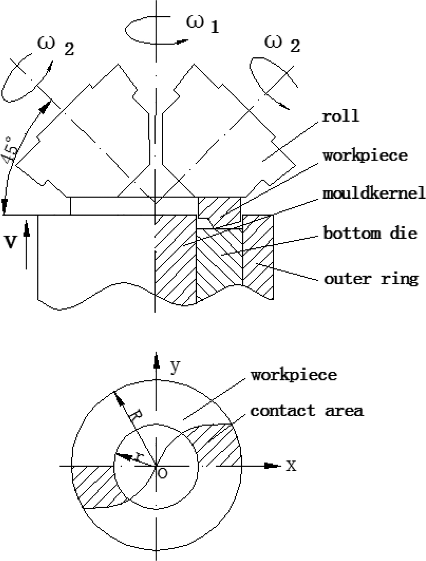
Schematic diagram of twin rollers rotary forging of spiral bevel gear
FE models
A part drawing of typical automotive rear axle drive spiral bevel gear we researched in this paper is shown in Fig. 2, and the detailed parameters of the spiral bevel gear are given in Table 1. 10
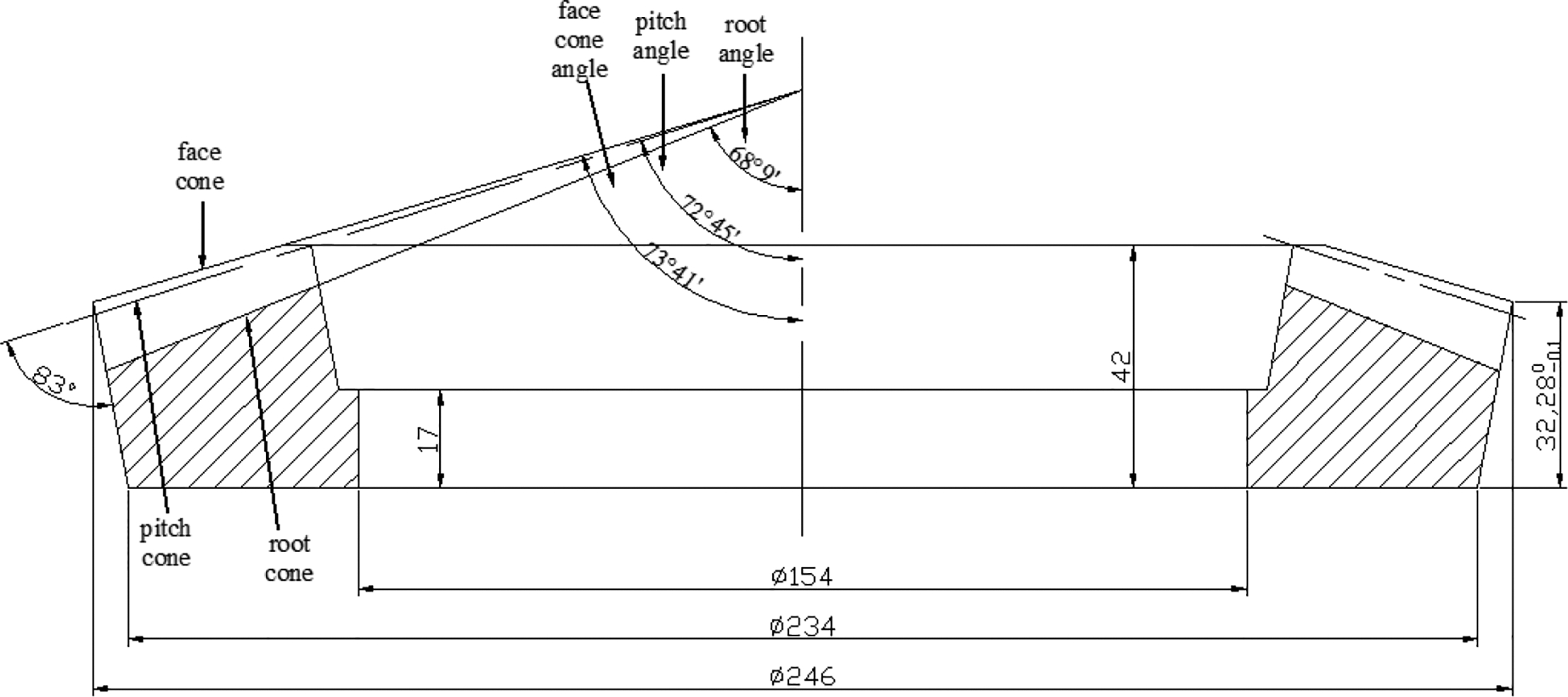
Part drawing of typical automotive rear axle drive spiral bevel gear (unit: mm)
Parameters of spiral bevel gear
A complete model of the spiral bevel gear was constructed in the PRO/E software, as shown in Fig. 3, by the establishment of spherical involutes, tooth lines, tooth surface, the rotation of gear body and the addition of the array of teeth.
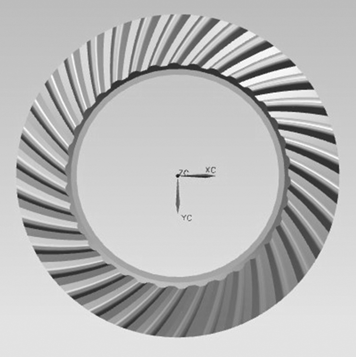
3D model of spiral bevel gear
The material of the spiral bevel gear is 20CrMnTi, the chemical composition of which is listed in Table 2. The gear belongs to large diameter gear as the external diameter of the spiral bevel gear is 246 mm. The large deformation zones of the spiral bevel gear are concentrated in the tooth profile, while the remaining area is mainly for rigid movement and deformed slightly. Whether the tooth is fully filled or not, the force of rotary forging is an important factor in deciding the best technology of production.
Chemical composition of 20CrMnTi steel/wt-%
Three technology models—open die, closed die and floating die—have been designed to simulate the gear's deformation.
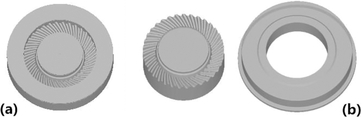
The depth of concave cavity in the open die model is the same as the height of the gear, which is shown in Fig. 4a . In the closed die model, both of the rollers have a step, and the depth of concave cavity is higher than the height of the gear. During the process of rotary forging, the step of the roller is always embedded in the bottom die, hindering metal flowing outside of the cavity, as shown in Fig. 4b .
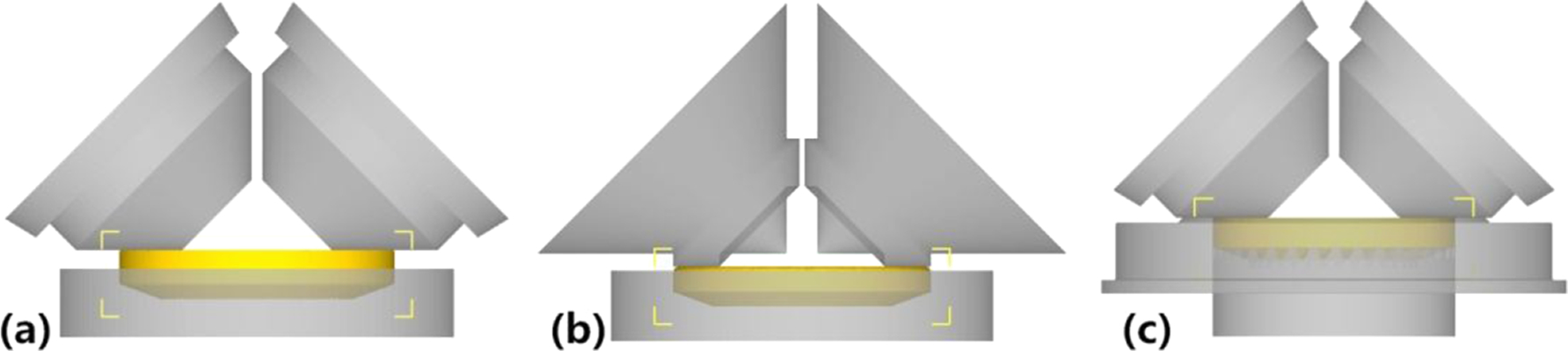
a open die model; b closed die model; c floating die model
The floating die model is shown in Fig. 4c . Compared with the previous two models, this model has a feature that the concave cavity is made up with the bottom die and the outer ring. A spring device is used to control the floating value of the outer ring in actual production. In the process of rotary forging, the outer ring moves downward relatively to the bottom die, forming a semiclosed cavity with the twin rollers.
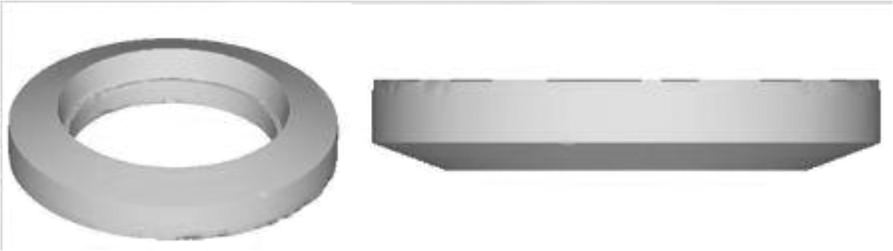
The bottom die of the open die and closed die models is shown in Fig. 5a , while the bottom die and outer ring of the floating die model are shown in Fig. 5b .
a bottom die of open and closed models; b bottom die and outer ring of floating model3D model of bottom die
According to the gear shape and the principle of volume invariably, the blank was designed as shown in Fig. 6.
3D model of blank
FE simulation
Process parameters
During the twin rollers rotary forging process, the elastic deformation of the material is much smaller than the plastic deformation. Therefore, rigid plastic model is used during the process of numerical simulation of spiral bevel gears.
The simulation temperature of the blank is set at 1000°C, while that of the dies is at 68°C. The blank is plastic and the dies are rigid. DEFORM-3D default mesh (tetrahedron element) was applied to model the blank. As the metal flows, stress and strain of the tooth shape are the focus areas, and local mesh refinement is done in tooth shape to improve the accuracy of the simulation result. In order to ensure the precision and convergence of calculation, the element is remeshed according to the mesh distortion condition at any time.
The smallest element size of the mesh in the simulation is 0.8 mm, the maximum size is 8 mm, and the size ratio is 10. The large deformation zone of rotary forging of spiral bevel gears is located in tooth shape, while the middle part is mainly for rigid movement. Thus, only small or even no deformation takes place. Moreover, due to the complex shape of the teeth, the local mesh needs to be refined. As can be seen from Fig. 7, the green areas show the regional element refinement.
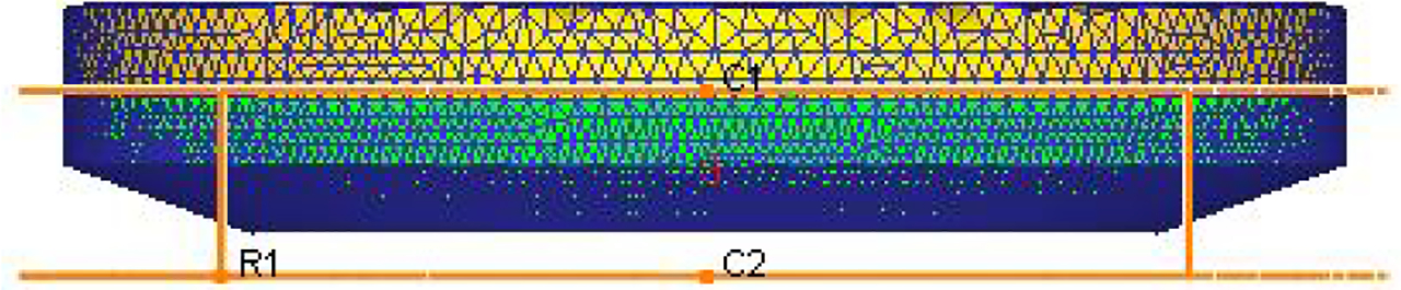
Refinement of regional grid
The revolution speed of roller is 10 rad s− 1, and the rotation speed is 16 rad s− 1; the feedrate of the lower die is 3 mm s− 1, and moving direction is upward. The friction type is set as shear friction, and the friction factor is 0.3. In order to ensure the continuous transmission of nodal force between the elements and reduce grid distortion, a smaller time step needs to be used in simulations. However, the smaller the time step, the longer the simulation time. Therefore, selecting the appropriate time step ensures both the calculation accuracy and efficiency. After several attempts, the time step was determined as 0.005 s per step. Simulation parameters are shown in Table 3.
Simulation parameters
Results and discussion
Deformation process
During the twin rollers rotary forging process, the spiral bevel gear is gradually formed, as shown in Fig. 8.
a 1 step; b 300 steps; c 600 steps; d 900 steps
As shown in Fig. 9, at the beginning stage of deformation, the blank and the bottom die contact together along the tooth trace, so the metal flows along the tooth trace of the bottom die. With the twin rollers continuously exerting local load on the blank, the deformation of two symmetrical regions of the blank gradually accumulated along the circumference. At last, the tooth shape of the gear is well filled with the metal.
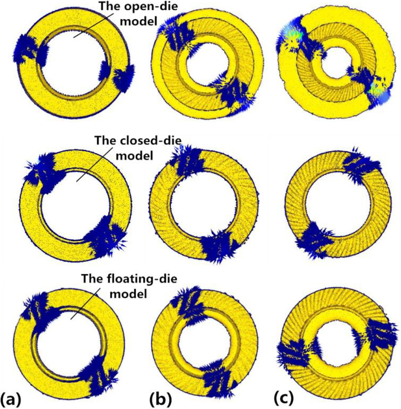
a 1 step; b 500 steps; c 900 steps
Distribution of stress effective
In the twin rollers rotary forging process, the contact area between the billet and the roller exists plastic deformation under the pressure of the roller. The forming process of spiral bevel gears by twins rollers rotary forging belongs to local accumulated deformation, and there are two symmetrical deformation areas about the gear's axis. As shown in Fig. 10, the stress effective distribution of the gear is symmetrical about the gear's centre axis during the processing of formation.
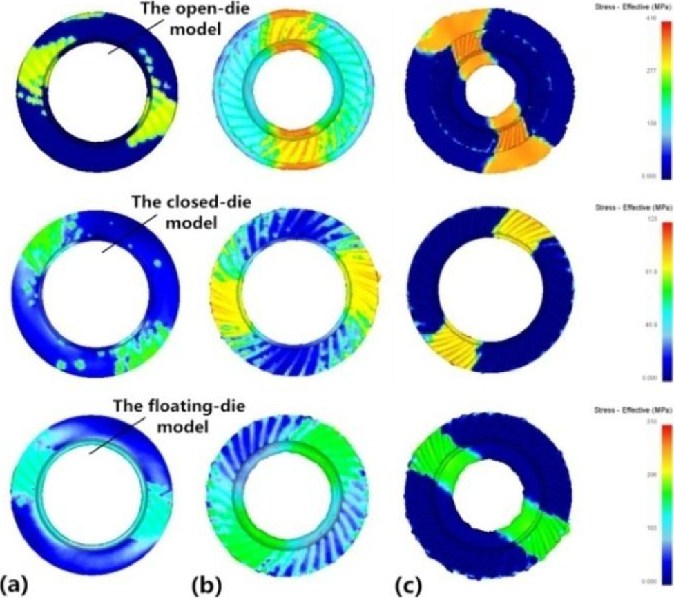
a 1 step; b 500 steps; c 900 steps
Filling effect of tooth shape
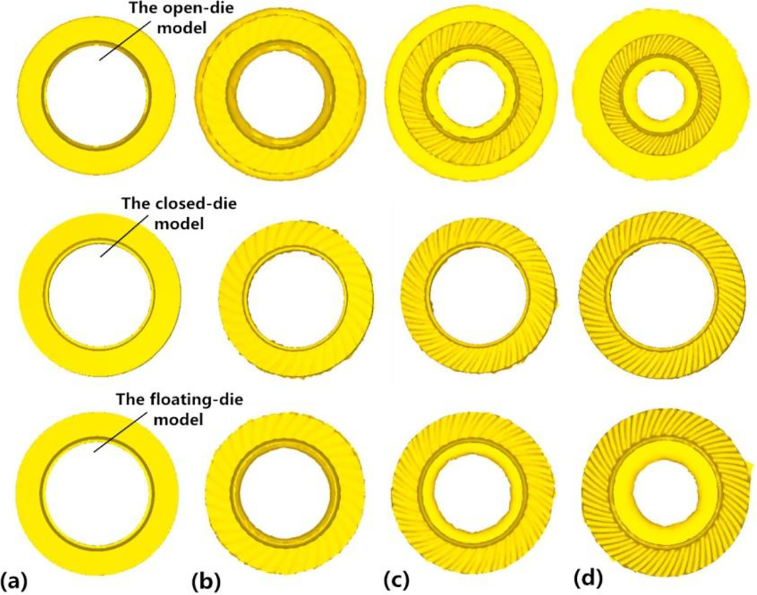
The simulation results of these three models are shown in Figs. 11–13.
Filling effect of tooth shape in open die model
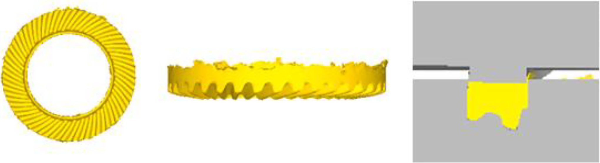
Filling effect of tooth shape in closed die model
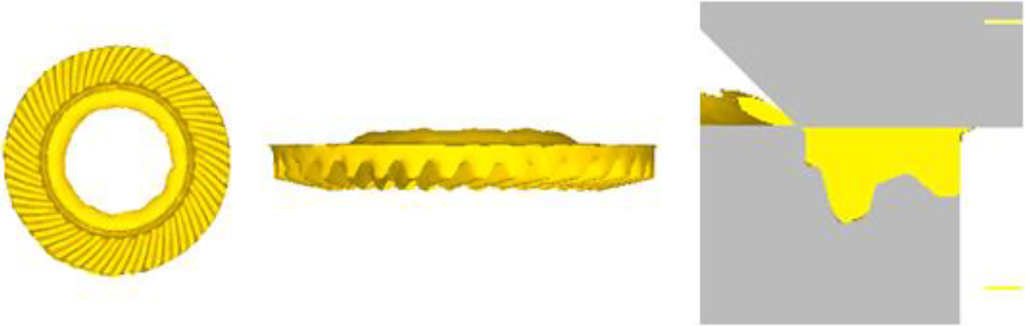
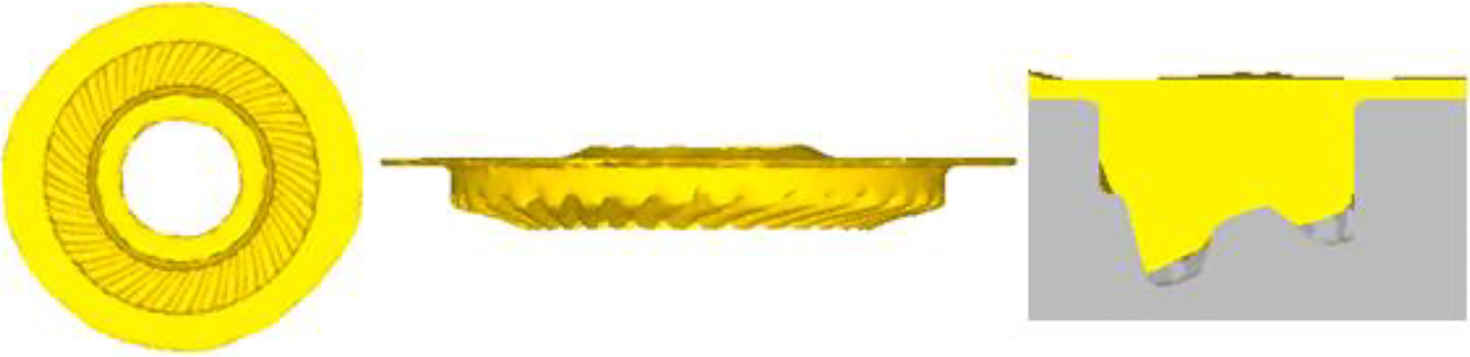
Filling effect of tooth shape in floating die model
As can be seen from Fig. 11, the spiral bevel gear in open die model is unsatisfactory because the tooth shape is not well filled with the metal and great flash formed in both outer and inner rings. That is because during the process of twin rollers rocking–rolling of spiral bevel gears,the deformation resistance of the metal contacted with twin rollers is smaller than that of the metal contacted with the bottom die; that is to say,the deforming velocity of the metal contacted with twin rollers is faster than that of the metal contacted with the bottom die according to the minimum resistance principle. Thus, the metal that contacted with twin rollers has the trend of outward expansion and great flash formed in both outer and inner rings,which leads less metal to fill the tooth shape of the gear (as shown in the cross-sectional view of Fig. 11).
As can be seen from Fig. 12, in closed die model, the gear can get clear tooth profile. That is because the step in the rollers is embedded in the bottom die, so the metal can only flow to the tooth shape and lengthwise direction because of the bottom die's constraint effect on the metal.
As can be seen from Fig. 13, in the floating die model, since the bottom die moves upward, a semiclosed die cavity is formed by the outer ring,twins rollers and the bottom die. The tooth profile that is finally obtained is very good and clear, and the inner ring of the gear has some small flash.
Forming force analysis
Figures 14–16 show the maximum forming force of twin rollers rotary forging in open die model, closed die model and floating die model respectively. The maximum forming force in open die model is 996 KN, in closed die is 521 KN, while in floating die is 665 KN. That is because in the open die model, great flash formed, which enlarges the contacting area between twin rollers and the billet, so the large forming force is needed to form the gear. However, in the closed die model,the contacting area between twin rollers and the billet is small,and great transverse flash would not be produced except some longitudinal flash. Therefore, smaller forming force of rotary forging is required. In addition, during the process of floating die model, since the bottom die moves upward, the relative motion direction of the outer ring is in accordance with the direction of the metal flowing, which is beneficial to the metal flow downward. The semiclosed die cavity formed by the outer ring,and twins rollers and the bottom die make redundant metal finally flowing to the inner ring, which avoids fold or not filling well.
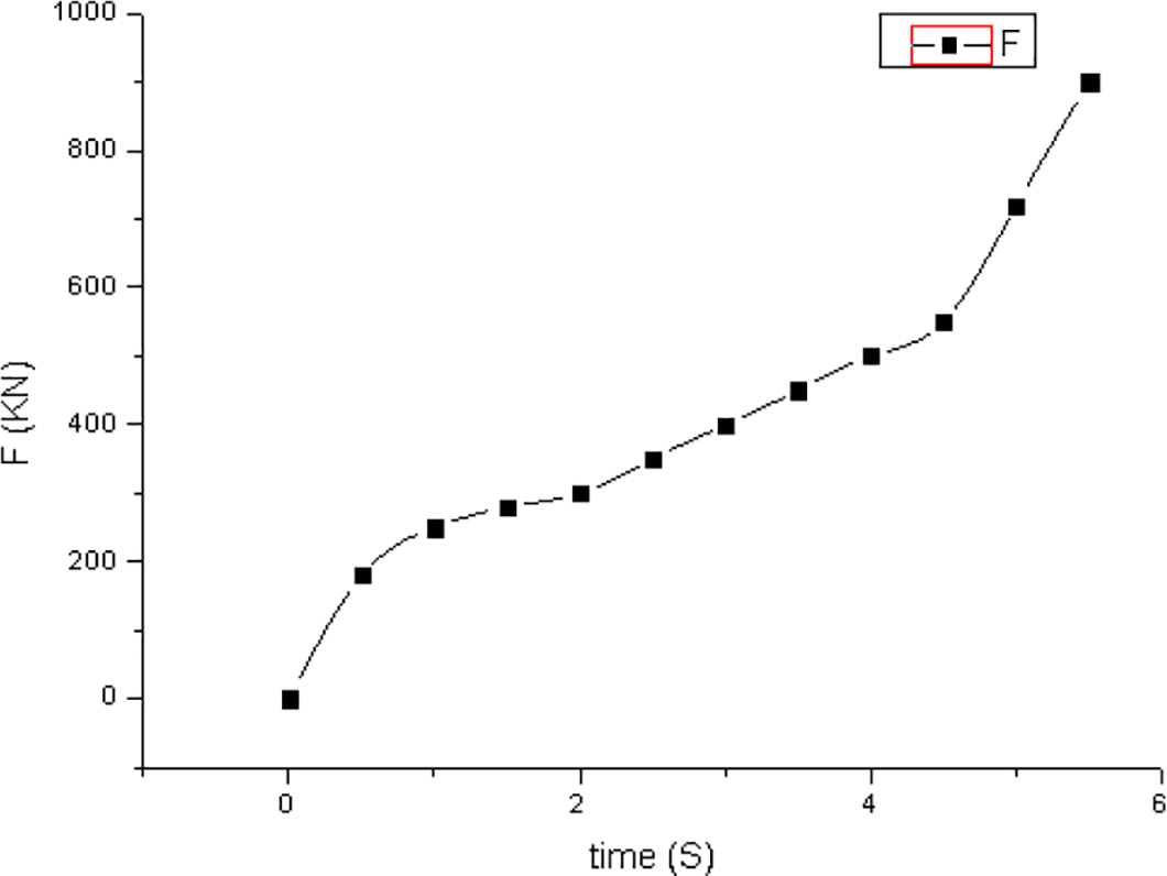
Forming force in open die model
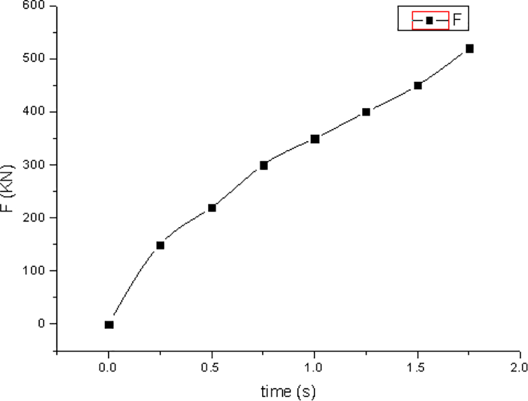
Forming force in closed die model
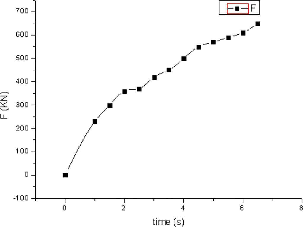
Forming force in floating die model
Theoretically speaking, closed die model can get full tooth profile of the spiral bevel gear and the forming force is the smallest. However, in the actual production, this method requires the equipment to have high assembly precision, and the rollers cannot have any eccentricity when assembled. Otherwise, the rollers and concave cavity will interfere with each other during the rotary forging process and damage the device.
In consideration of the tooth shape filling effect, material utilisation and moulding equipment tonnage, the floating die model technology was chosen to produce the gear.
Experimental
Verification of 3D FE model of twin rollers rotary forging
According to the simulation parameters and results, the open die, closed die and floating die moulds were fabricated, and 20CrMnTi gear billet was machined for experiments. Figure 17 shows the 20CrMnTi gear billet, Fig. 18 shows the equipment of twin rollers rotary forging, and Fig. 19 is the contrast of the spiral bevel gear that formed in the experiments. From Fig. 19a , it can be seen that the outer and inner circle of the gear generates great flash when deformed in the way of the open die rotary forging and the tooth shape is not filled very well with the metal. Instead, a little flash in the inner circle of the gear is generated when deformed in the way of the floating die rotary forging and the tooth shape is well filled with the metal as shown in Fig. 19c . Because of the way of the closed die rotary forging process, it can also get full tooth shape and nearly have no flash as shown in Fig. 19b . As is mentioned above, in this method, the equipment requires high assembly precision. Therefore, in practical production, we prefer the floating die method to produce the spiral bevel gear.
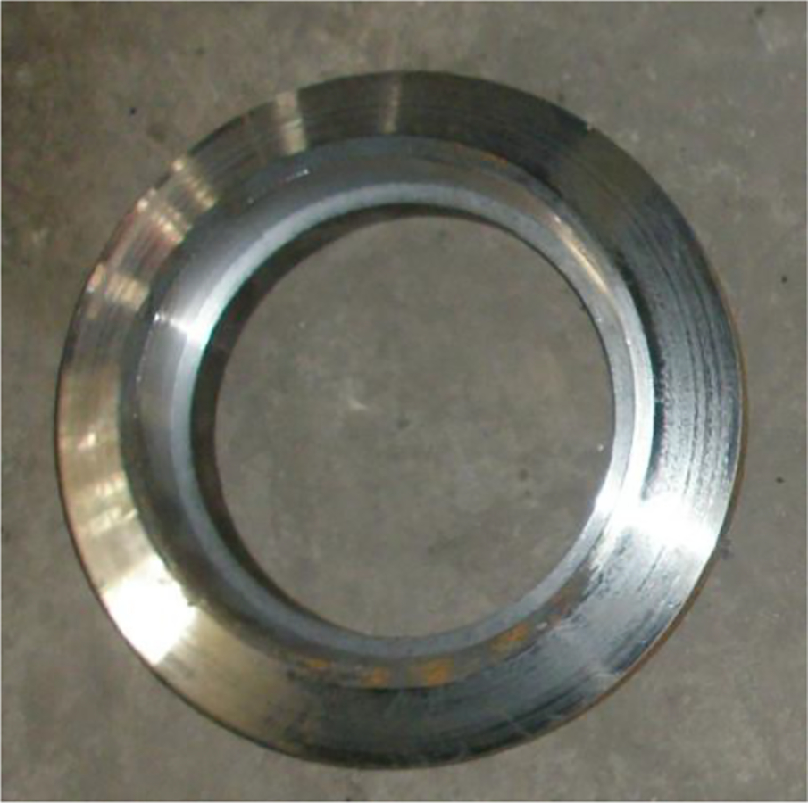
20CrMnTi gear billet
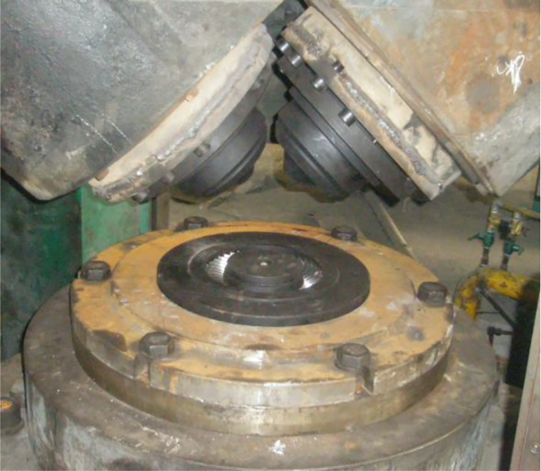
Equipment of twin rollers rotary forging
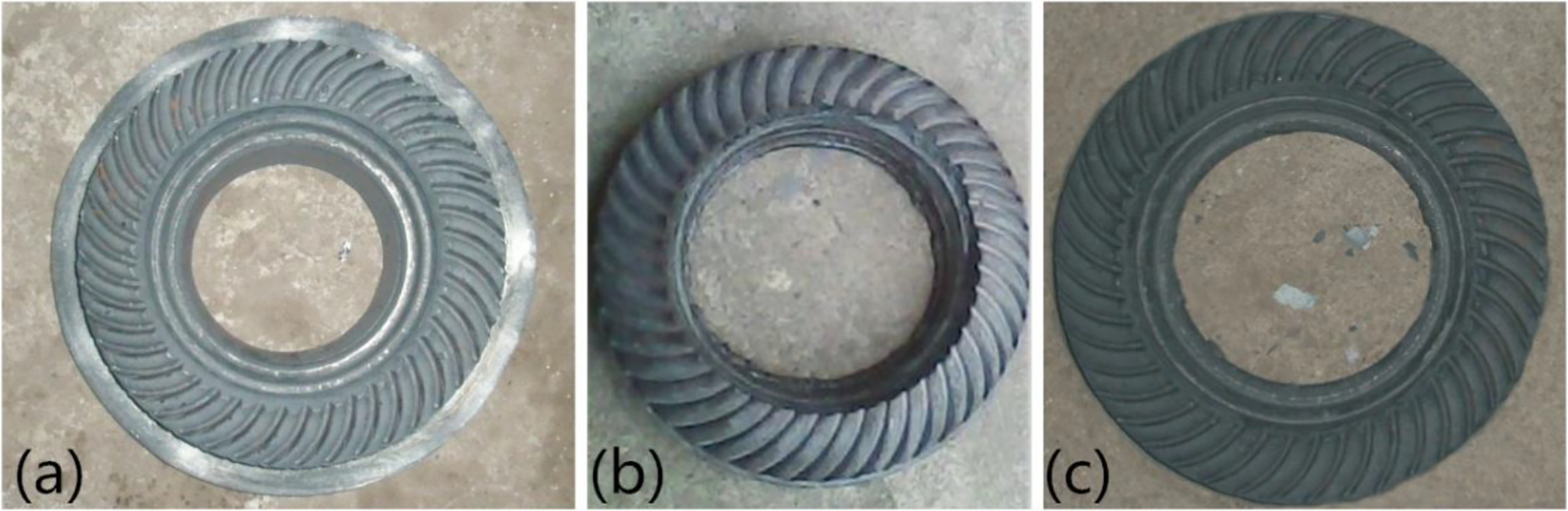
a formed in open die model; b formed in closed die model; c formed in floating die modelDeformed spiral bevel gear in experiment
Microstructure of 20CrMnTi spiral bevel gear
After the heat treatment process such as isothermal normalisation, surface carburisation and quenching, the distribution of microstructure of the spiral bevel gears formed by twin roller rotary forging, which adopted the floating die model, was observed; the microhardness was measured; and then the results with the spiral bevel gear that formed by machining were compared.
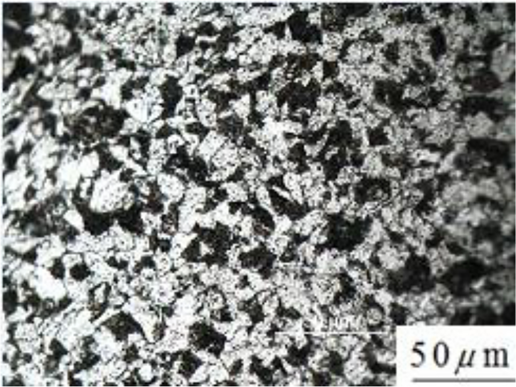
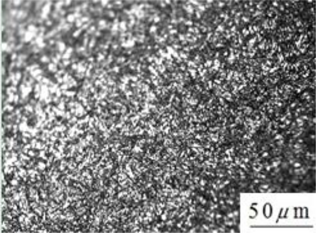
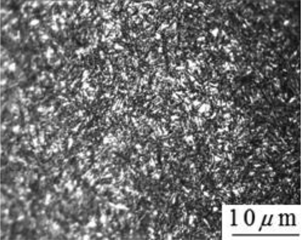
The original microstructure of spiral bevel gear material consists of ferrite and pearlite, which belong to sub-eutectoid steel and high strength low carbon steel. The microstructure of the addendum has been refined well after hot twin rollers rotary forging, as shown in Fig. 20. After isothermal normalisation, the microstructure can be further refined, as shown in Fig. 21. Finally, after surface carburisation and quenching, the microstructure of this part constitutes plate martensite, carbide and some residual austenite, achieving the greatest degree of grain refinement, as shown in Fig. 22.
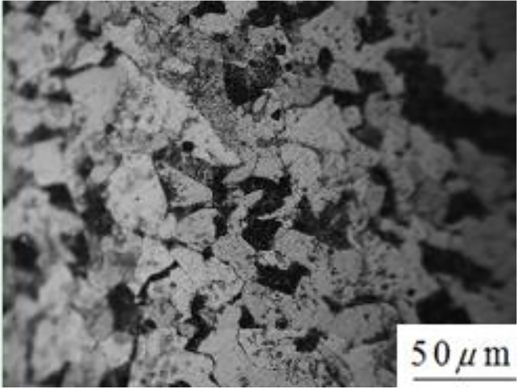
Microstructure of addendum after twin roller rotary forging
Microstructure of addendum after isothermal normalisation
Microstructure of addendum after surface carburisation and quenching
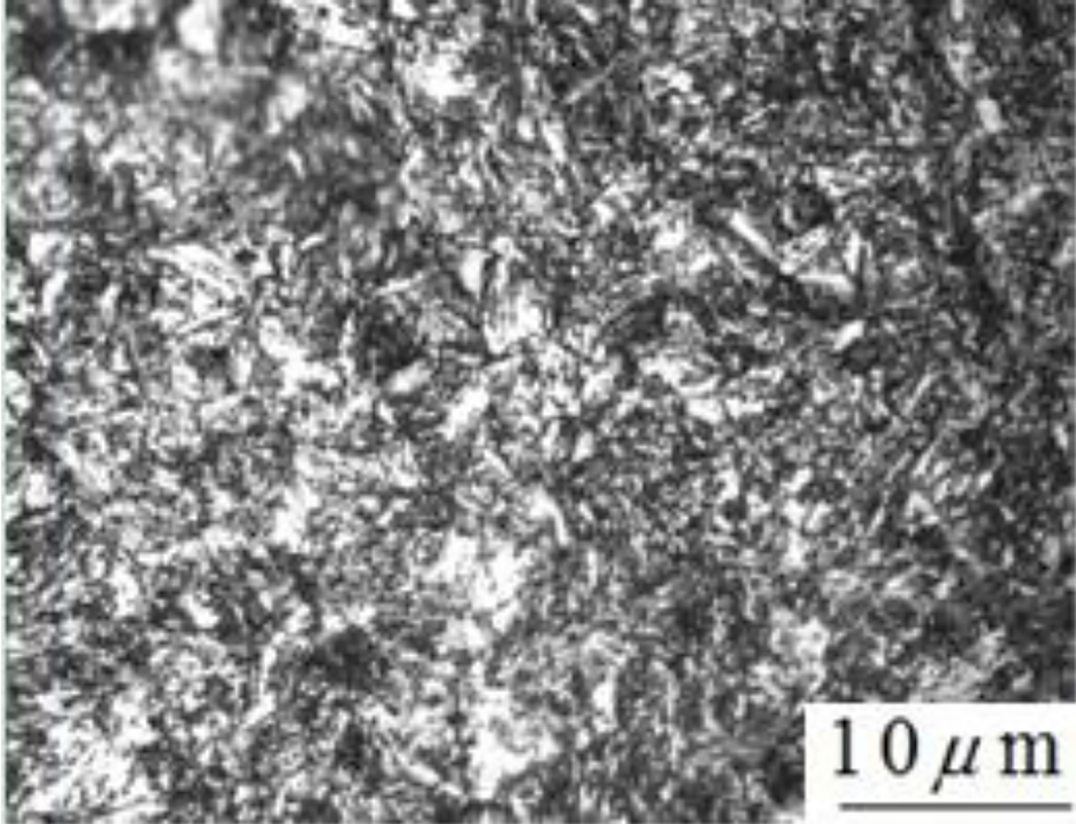
From Figs. 23 and 24, we can see that the plate martensite in the addendum after machining and quenching is more coarse than that after twin rollers rotary forging and carburised quenching process (if there is coarse martensite after the quenching process, the strength and toughness of carburising parts will significantly decreased), and the concentration of white carbide is much more higher. The size of martensite of fibrous tissue after rotary forging and carburising and quenching process is smaller, and the white carbide distribution is more uniform. So the hardness and strength are higher than that of the spiral bevel gear that formed by quenching after machining process. Moreover, the microhardness of the gear that formed by twin roller rotary forging reached 457.8 HV (an increase of 110.0 HV), improving by ∼31.7% when compared with the gear that formed by machining. These sufficiently prove that the technology of twin rollers rotary forging is superior to the conventional machining process.
Microstructure of addendum (surface carburisation and quenching after rotary forging)
Microstructure of addendum (quenching after machining)
Conclusions
In consideration of the tooth shape filling effect, material utilisation and moulding equipment tonnage, the floating die model is the optimal method to produce the spiral bevel gear. The tooth shape of the gear is well filled with billets, and the maximum forming force of twin rollers rotary forging is 665 KN. The experiments with 20CrMnTi gear billet verified the feasibility of the technology of twin rollers rotary forging of spiral bevel gears. The experiment results coincide with the simulation results and thus provided a scientific basis for actual production of the spiral bevel gear. After the heat treatment process, the microstructure of the spiral bevel gear that formed by twin rollers rotary forging is more uniform and refined than the spiral bevel gear that formed by machining and quenching process. In addition, the microhardness of the gear that formed by twin roller rotary forging reached 457.8 HV (an increase of 110.0 HV), improving by ∼31.7% when compared with the gear that formed by machining.
Acknowledgements
We would like to thank the National Natural Science Foundation of China for Distinguished Young Scholars (grant no. 50725517) for the support given to this research.