
Abstract
The zinc flow in a galvanising bath is numerically simulated for three cases, and the flow field is analysed using three-dimensional views. It is found that the flow near the zinc surface directs from the strip to the ingot side when inductors are equipped and whether ingots are melting or not, and the flow direction is opposite to that near the zinc surface for the case without inductor and ingot, which does not exist during the bath operation process. Whirlpools are found to be formed between the snout and the bath side walls, which will increase the chance of dross particles touching the strip surface. Some effective measures are proposed to stop more dross from adhering to strip. This work will lay foundation for the optimisation of the galvanising process to improve the coating quality of steel strip.
Introduction
The hot dip galvanising process is used to form a galvanising coating on the surface of steel strip to improve the corrosion resistance performance of steel sheets for cars, television sets, etc. Usually, in a zinc alloy bath, the core component of a galvanising line, there are channel inductor, sink roll, guide roll, steel strip, snout and ingot used for galvanising. The steel strip is rapidly immersed and continuously coated by zinc whose temperature is normally between 450 and 480°C (Figs. 1 and 2). 1 The hot dip galvanising process is a complex metallurgical process (Fig. 3). The operational parameters, such as product specification, strip parameters (e.g. strip speed, strip temperature and iron strip dissolution), bath configuration, placement and dissolution pattern of ingots of zinc alloy, inductors, heat dissipation through walls, as well as bath chemistry, can influence the characteristics of the fields of flow, temperature and the dissolved aluminium and ferrum concentrations (three fields) in the bath 1–3 and they can influence the dross formation and the coating quality of steel strip.
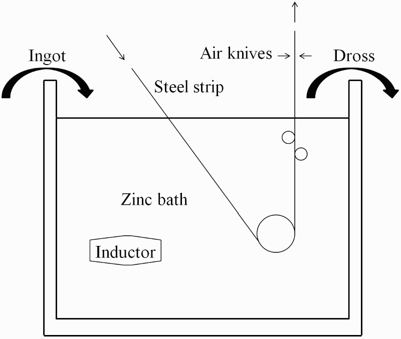
Schema of galvanising bath operation
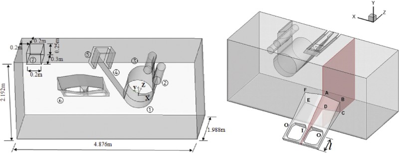
Computational domain of bath with two views (1: sink roll; 2, 3: guide roll; 4: steel strip; 5: snout; 6: inductor; 7: ingot)
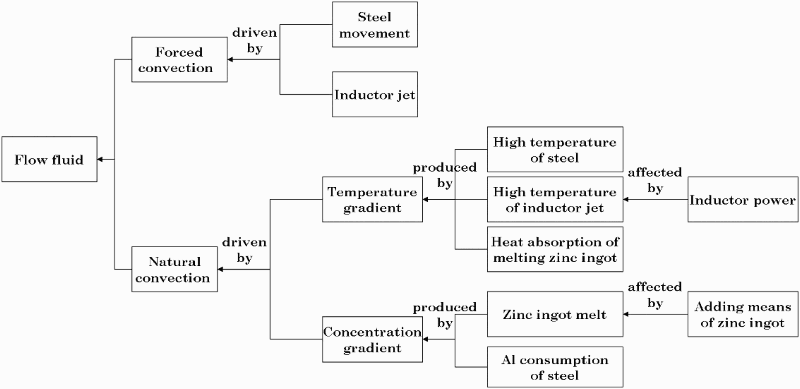
Moving mechanism of zinc liquid in bath
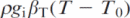
The dross formation rate should be minimised by optimising operational parameters. 4 In this case, how to minimise the effect of dross particles to the strip coating is an essential issue. Dross formation on strip is a common factor inducing strip surface coating defect. It is necessary to study the characteristics of the flow field and propose effective measures for flow control. The moving mechanism of zinc fluid in the galvanising bath is complex (Fig. 3), which is driven by both forced convection and natural convection. The zinc flow in the bath is not only forcefully driven by strip movement and inductor jet but also by the temperature gradient and the concentration gradient mainly of Al. The temperature gradient is mainly produced by the high temperature of the strip, the high temperature of the inductor jet and the low temperature around the ingots due to the heat absorption of the ingot melting. The concentration gradient is mainly produced by the ingot melting and the Al consumption of the strip.
Engineers and researchers have investigated the characteristics of the flow field in the bath and taken some measures to reduce the chance of dross formation on steel strip. Kurobe et al. 5 studied the flow field in experiments of 1:5 and 1:10 scale cold baths. Water was used instead of zinc, inductors were not equipped and ingots were not added. The flow streamlines in the symmetry plane and the plane in the depth direction near the surface are shown by the measurements in the 1:5 scale cold bath. The velocity vectors in the lengthwise planes and the widthwise planes were shown by using a computational fluid dynamics for demonstrating the basic features of flow driven by both forced convection and natural convection and the effects of strip movement, ingot melting and inductor jet. 1,6–12 Park et al. 13 and Zhou et al. 14 numerically simulated the magnetic field, electric field and three fields inside the inductors attached to a galvanising bath. The former further presented the velocity vectors in the symmetry plane and the widthwise planes. Dash et al. 15 numerically simulated the zinc flow in a continuous galvanising bath by assuming the zinc inside the bath to be isothermal. The velocity vectors in the lengthwise planes showed that the vortex is formed between the strip and the sink roll because of the movement of the strip over the sink and guide rolls and can feed the dross particles back to the flow again, and the dross is picked up by the strip, thus influencing the strip coating quality. Effective flow barriers, i.e. two alternative arrangements of placing a parallel or perpendicular plate baffle is proposed to be used to eliminate vortex in the flow field generated. However, most of the above work about flow field is based on two-dimensional (2D) planes. In this case, it is difficult to determine the overall movement of zinc with dross particles. To date, little work on the analyses of the flow field in the galvanising bath using three-dimensional (3D) views has been reported in the literature.
In this paper, the zinc flow field in a galvanising bath is simulated numerically under various conditions, and the flow distribution using 3D views is analysed. Some physical measures are proposed to reduce the influence of the dross on the strip coating quality.
Modelling
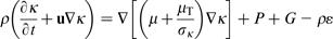
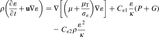
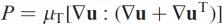
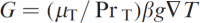
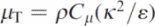
The zinc flow was modelled as an incompressible fluid described by Navier–Stokes equations. One half of the bath was modelled since the zinc bath is symmetrical with respect to the midplane in the lengthwise direction. The unsteady incompressible flow and heat transfer can be described using the 3D mathematical model governing equations including continuity, momentum, energy and standard k–ε turbulence equations based on an assumption of the Newtonian fluid:
Continuity equation
Momentum equations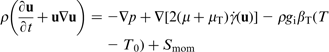


Energy equation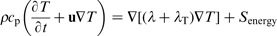


Equation for the turbulent kinetic energy K


Species mass conservation equation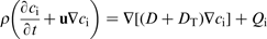

In our model, the numerical scheme for calculation used is the finite volume method. The solutions of equations carried out in this work are based on the algorithm SIMPLE proposed by Patankar. 15 Pressure is discretised with the standard scheme, while the momentum, turbulent kinetic energy, turbulent dissipation rate and energy equations are discretised with the first order upwind scheme.
Results and discussion
Model for simulation
Taking a galvanising bath as an example, a study of the performance of a galvanising bath in the respect of fluid flow and heat transfer has been carried out. One-half of the galvanising bath attached with the inductors is modelled as shown in Fig. 2. The bath is 4.876 m long, 3.976 m wide and 2.192 m deep. The channel inductors are installed at the two sides of the bath, with an incline angle of 60° to the vertical plane. Two ingots are submerged below the zinc surface at the two corners of the bath as shown in Fig. 2. The distance from points A or D to the right bath wall is 1.526 m, that from points B or C to the right bath wall is 0.954 m and the distances from points A, B, C and D to the bottom bath wall are 1.156, 1.082, 0.712 and 0.650 m respectively. The cross-section of the bath containing the longitudinal symmetry plane of the inductor centre is highlighted. The selected inlet and two same size outlets respectively denoted by I and O are shown on a horizontal line. The area of the O outlet section reaches 57.08 cm2, and the area of the I inlet section is 88.80 cm2. The inlet and two outlets are 47.85 cm away from the bottom centreline of the inductor, that is, l = 47.85 cm.
The model geometry is meshed with structured and unstructured grids. The thermophysical properties of materials used in the simulation are presented in Table 1. Proper boundary conditions are given for the model. Strip, the sink roll and guide rolls are set as a moving wall boundary, and the other walls of the bath were set as stationary wall boundary. No slip condition is given for all the walls. The inlet and two outlets of inductor is used as the outlet and two inlets of the bath model, and the bath inlet velocity can be estimated from Ref. 14 according to the specified inductor power as presented in Table 2. In this work, the ingot is assumed to be added continuously at the corner of the bath and melt at a velocity of 0.3838 kg s− 1, as presented in Table 2. A grid independence test has been carried out in order to choose a reasonable number of cells.
Thermophysical properties of zinc
Selected operational parameters of galvanising bath
Top thick dross layer.
Snout region.
Strip outlet region where no dross layer covers the zinc fluid.
Two-dimensional views of flow field
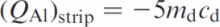
In order to study the zinc flow characteristics in the bath comprehensively, we simulate the 3D flow fields for three cases: case 1, without inductor and ingot; case 2, with inductor and without ingot; and case 3, with inductor and ingot. The selected operational parameters of the galvanising bath as presented in Table 2 are used for calculation. The 3D flow field in the bath is very complex. In order to demonstrate the general zinc flow in the bath, Fig. 4 shows the 2D velocity vectors and some streamlines in the bath lengthwise section across the middle in the width of the strip using the continuous ingot adding method based on an assumption of small enough time interval.
a case 1; b case 2; c case 3Velocity vectors and some streamlines in bath for three cases
As shown in Fig. 4, for case 1, the flow near the zinc surface of the bath directs from the ingot location to the strip because of the forced convection resulting from the strip movement and the large viscosity of zinc. This phenomenon is the same as that found by Kurobe et al. 5 in the experiments of 1:5 scale cold bath without inductor and ingot. For case 2, a vortex is formed due to the inductor jet, and the vortex is in a counterclockwise direction driven by the hauling effect due to the strip movement. This induces the flow on the zinc surface of the bath to direct from the strip to the ingot location. For case 3, a vortex is formed due to the inductor jet, and the vortex has a larger range in a counterclockwise direction driven by the hauling effect due to both the strip movement and the downflow produced by the ingot melt. The cone of the vortex in this case is placed at the position deeper than that in case 2, but the flow also directs from the strip to the side where ingots are placed. During the operation of the bath, the inductors are on load all the time, the ingots are submerged over several time intervals and the dross on the zinc surface is not moved. The thick dross layer is therefore formed, which can act as an effective thermal protective coating of the bath. Therefore, case 1 does not occur, and in the latter two cases (cases 2 and 3), the zinc flow on the zinc surface of the bath directs from the strip to the ingot location. In fact, the surface dross layer will maintain a certain thickness from the beginning of the operation to a steady state, and for the latter two cases, the flow with a horizontal velocity of about 0.02 m s− 1 will recarry some formed fresh dross into the bath, and thus, the fresh dross is finally rolled onto the strip surface to influence the strip galvanising quality. In order to reduce the quantity of the formed dross and the influence of the dross on the strip galvanising quality but not to reduce the thermal protective effectiveness (i.e. the formed surface dross layer would be moved), some effective measures should be taken in the future.
Three-dimensional views of flow field
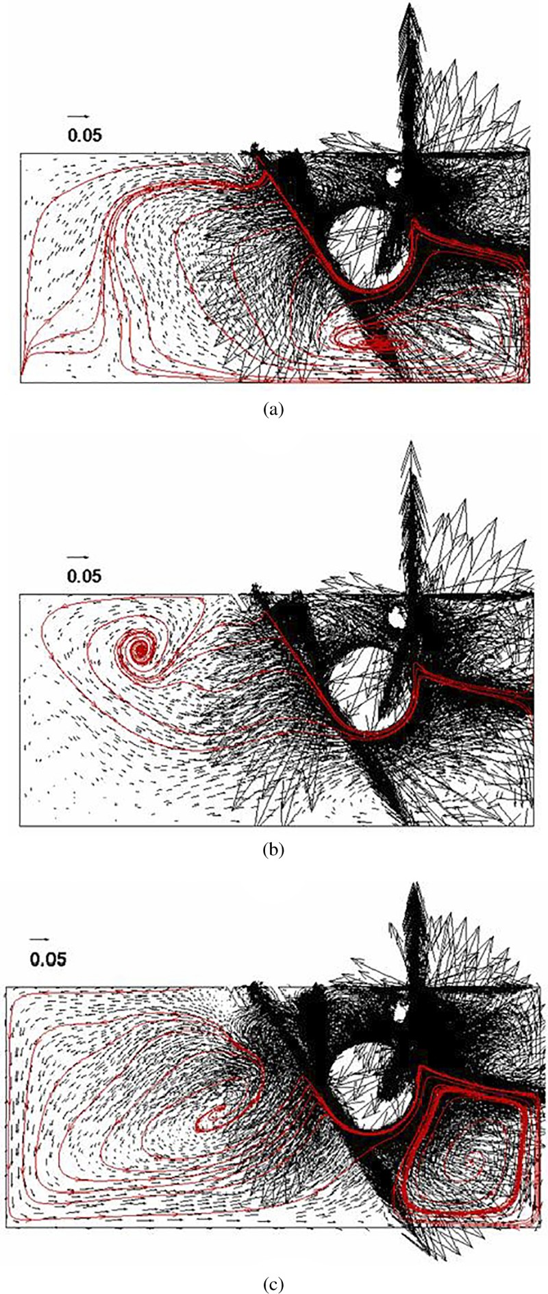
The V typed area is the most closed area in the bath. In the area, several vortexes formed possibly roll some dross particles onto the strip surface (Fig. 4). 1,12,15 A vortex is formed between the strip and the sink roll in the V typed area due to the movement and over the sink roll. The dross generation area is somewhere near the snout. Under the effect of the vortex, freshly generated dross particles easily touch the strip surface on which the coating is being formed. The vortex is, therefore, considered to be dangerous. 12,15 Next, we want to know whether there are dangerous special flows outside the V typed area.
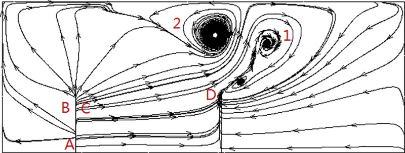
Due to the blockage by all the components and the shearing force by strip movement, some obvious vortexes or whirlpools can possibly be formed. In order to demonstrate the flow around the strip between the snout and the sink roll clearly, the zinc flow inside the bath (for case 1 without inductor and ingot) without two guide rolls is simulated. Streamlines demonstrating the flow pattern near the bath surface are displayed in Fig. 5. In this figure, two large and one small whirlpools are formed between the snout and the bath sides, and the large whirlpool 1 and the small one have an identical direction of rotation, which is opposite to the direction of rotation of the large whirlpool 2. In order to demonstrate the flow around the whirlpools and the effect of the whirlpools to the strip, some streamlines of the 3D zinc flow of the two large whirlpools are displayed in Fig. 6. In this figures, the two whirlpools can be seen clearly. Although the two whirlpools are outside the V typed area, the dross particles on the bath surface especially the freshly generated dross particles around the snout will be sucked into the whirlpools and enters the V typed area where a weak negative pressure is generated due to strip movement. This will, to a large extent, increase the chance of the dross particles touching the strip surface, which is helpful for the dross particles to adhere to the strip. The two whirlpools can, therefore, lower the strip coating quality. Some effective measures should be taken to stop more dross from adhering to the strip, for example, to stop the whirlpools from being formed, to increase the frequency of cleaning the dross on the surfaces, especially the freshly generated dross, and to isolate the area of generating fresh dross particles from the whirlpools.
Flow pattern near bath surface
a whirlpool 1; b whirlpool 2Some streamlines of three-dimensional flow of two large whirlpools
Conclusions
The zinc flow field in a galvanising bath is studied, which affects dross formation on a steel strip. The zinc flow near the zinc surface is found to direct from the strip to the ingot, for case 2 with inductor and without ingot and case 3 with inductor and ingot, which is opposite to the flow direction near the zinc surface for case 1 without inductor and ingot, which does not exist during the bath operation process. Based on these, a salvage device is proposed to be placed near the ingot location and a little below the surface of the bath to salve a part of dross. Whirlpools are found to be formed between the snout and the bath side walls, which will, to a large extent, increase the chance of dross particles touching the strip surface. Some effective measures are proposed to stop more dross from adhering to strip. This work is expected to lay foundation for the optimisation of the process of the galvanising line to improve the galvanising quality of steel strip.