
Abstract
Strips (1.6 mm thick) of Fe–6.5wt-%Si alloy were prepared by twin roll casting. The microstructure was found to be mainly columnar and equiaxed grains. The plastic deformation of the strip is inhomogeneous in the thickness direction. The most serious deformation is located at a certain depth from the strip surface. The influence of mechanical factors on the solidification structure of the strip is discussed. As the two solidifying shells contact with each other at the end of solidification, the columnar growth fronts break into fragments, which finally grow into equiaxed grains. At the hot rolling stage, the inhomogeneous deformation of the strip is attributed to the fact that the ductility of the alloy is sensitive to temperature. There is a large temperature gradient in the thickness direction, which can be up to 510°C mm− 1.
Introduction
Twin roll casting (TRC), which embodies the near net shape concept, is a relatively new technology of continuous casting and rolling. With several advantages over conventional sheet making process such as a reduction in total costs and time, low energy consumption and avoidance of several thermomechanical treatments, TRC has been used to prepare aluminium, magnesium, steels and shape memory alloys. As a cooling rate of 102–103 K s− 1 can be achieved, it has also been utilised to fabricate sheet products of bulk amorphous alloys. 1
High silicon non-oriented electrical steel sheet containing 6.5wt-%Si possesses excellent properties, such as minimal magnetic losses and near zero magnetostriction and is very suitable for the production of advanced transformers, power generators and electromagnetic shielding devices working at a high frequency. 2,3 However, the plasticity and toughness of the material decrease sharply with temperature ( < 400°C) because Si has considerable solid solubility in Fe, and a number of brittle ordered phases (B2 and DO3 phases) exist. 4,5 This leads to an issue that the traditional technologies such as warm and cold rolling cannot be used to prepare the material. As high silicon steels have good plasticity at high temperature, Liu et al. 6,7 have been trying to prepare this alloy by TRC.
In the TRC process, strips can be continuously prepared from the melt between the rolls. Because the flow and temperature fields are complex and the solidification process is completed in a very short time ( < 0.5 s), 1 real time observation and precise measurement are unable to be achieved, so numerical models are used. Hwang et al. 8 simulated the transient fluid flow, heat transfer and solidification behaviours during the early stage of the process. Zhang et al. 9 carried out a numerical simulation on the stress field of austenite stainless steel during the TRC process. Wang et al. 10 simulated the microstructure of steel strip TRC. The influence of the casting conditions such as pouring temperature and heat transfer coefficient between the rolls and the solidified strip on the strip solidification microstructure was investigated. However, one question in the problem of strip formation has not been noticed. This is the relationship between the strip deformation and the temperature gradient in its thickness direction.
The deformation behaviour during strip casting was experimentally simulated by hot rolling of Al alloy with a temperature gradient through the thickness direction. 11 Using this method, Park et al. 11 identified different types of strain in the strip. However, there are some differences between simulation and reality. First, in the simulation, the friction between the aluminium sheets and the roll surface is great because their speeds are different. This leads to a situation that the maximum shear strain occurs at the surface of the sheet, while there is almost no friction between the strip and the roll surface in a TRC process because the grains grow attached to the rotating rolls. Second, although the temperature gradient in the strip with a symmetrical distribution was taken into account in the simulation, the influence of temperature on material ductility was not considered.
In order to solve the problems mentioned above, an Fe–6.5wt-%Si alloy was used to carry out the present study, which enables us to discuss the inhomogeneous deformation caused by the large temperature gradient in the thickness direction of the strip during the TRC process.
Experimental
According to the phase diagram of the binary Fe–Si system (see Fig. 1), 12 the liquidus temperature for the Fe–6.5wt-%Si alloy is ∼1445°C. Taking industrial pure iron and silicon iron alloys as raw materials, an Fe–6.5wt-%Si alloy was melted in a vacuum furnace. The melt superheat was maintained at ∼70°C. The strip casting experiment was carried out using a vertical type twin roll strip caster, whose schematic diagram was shown in the previous study. 13 When TRC began, the melt entered the gap between the rolls. The cylindrical rolls, 500 mm in diameter and 150 mm in length, rotated at a speed of 35 m min− 1, and the molten pool was controlled to be 120 mm in height. At the exit of the caster, an infrared thermometer was used to record the temperature of the strip surface. The temperature was in the range of 940–980°C, and the median (960°C) was taken as the average. The strip is 110 mm in width and 1.6 mm in thickness. Microstructural characteristics of the strip were analysed with optical microscopy and an electron microprobe (EPMA-1720). The fracture appearance was observed using a scanning electron microscope (SEM, Quanta 400). The hardness of the strip was evaluated using a Vickers hardness tester (MHV-30Z).
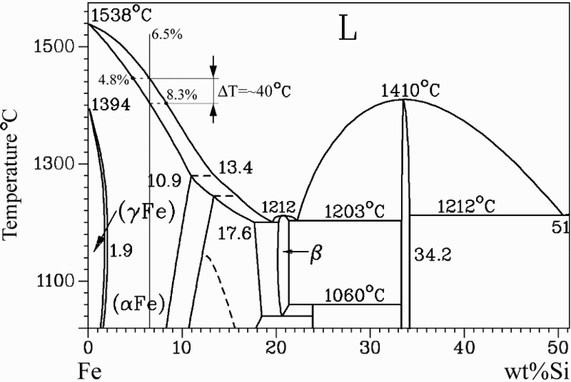
Phase diagram of binary Fe–Si system
Results and discussion
Figure 2a shows the surface morphology of the strip. It has a flat surface with a homogeneous thickness of 1.6 mm. At room temperature, the alloy is very hard and brittle. The fracture morphology of the strip is shown in Fig. 2b , and steps and river patterns, which are a characteristic feature of cleavage fracture, can be observed on the fracture surface. The average hardness is 403.5 HV0.05 (five values were obtained, which are 393.8, 401.1, 402.3, 409.7 and 410.6 HV0.05 respectively). These results indicate that the workability of the steel is poor at room temperature. The X-ray diffraction (XRD) pattern of the strip is shown in Fig. 2c . α-Fe and B2 (FeSi) are identified in the sample. It is reported 4,5 that the poor workability of the steel at room temperature can be attributed to the high solid solubility of Si and the formation of brittle phases such as B2 (FeSi) and DO3 (Fe3Si).
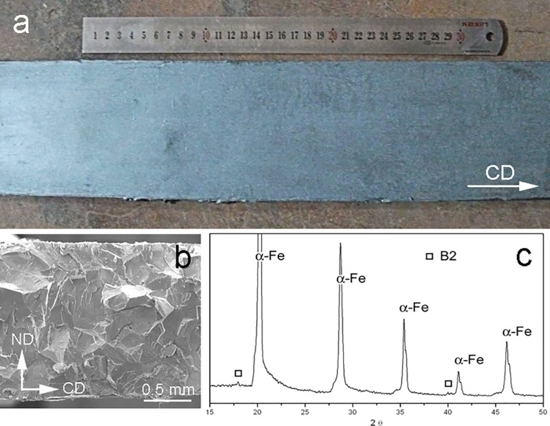
Twin roll casting strip of Fe–6.5wt-%Si alloy a is surface morphology of strip, b is fracture morphology and c is XRD pattern (ND is normal direction)
The cross-section view of the strip by optical microscopy, and electron probe microanalysis is shown in Fig. 3. It can be seen that the strip has a symmetrical structure. Strong columnar grains in a regular manner are found on both sides of the centreline. In the surface layer of the strip (s = 1.00), the grains grew in the direction perpendicular to the casting direction (CD). Then, they gradually tilted in the direction opposite to CD, which can be identified by the deformation lines. Figure 3a shows a clearer image. Small equiaxed grains are found in the central zone of the strip, with an average diameter of ∼30 μm. The columnar grains in the surface layer are larger. Their growth direction begins to tilt at the position s = 0.80, and the rotation angle can be up to 20°. At the root of the columnar grains, the boundary is straight, and no subgrain boundary is found, while at the top of it (s = 0.50), many small subgrains are observed. Meanwhile, the boundaries of the columnar grain are gradually curved from the root to the top.
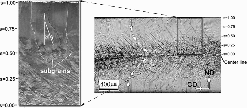
Cross-section view of strip by optical microscopy and electron probe microanalysis respectively
Twin roll casting is not a simple solidification process. The mechanical factors must be considered in order to analyse the formation of the strip microstructure. The TRC process can be divided into two stages: the first for crystal growth and the second for hot rolling. The dividing point is set at the solidification end point. Figure 4 shows the sketch of the TRC process. Above point b, the shell on each roll surface grows independently. The strip forms at point b and begins to deform as the rolls rotate.
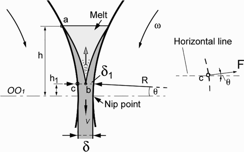
Sketch map of TRC process (rolls rotate in opposite directions with same angular velocity ω). v is casting speed. Height of molten pool h is defined as vertical distance from melt surface to horizontal line OO1, which connects two circle centres. R is roll radius, and θ is angle between OO1 and radius. Solidification end point (point b) was at height of h 1 above OO1. δ is gap between rolls, and δ1 is strip thickness at point b
In the TRC process, the temperature in the centre of the strip is higher than that at the surface because of the existence of the molten pool between the rolls; therefore, there is a temperature gradient in the strip. The liquidus temperature of the alloy is ∼1445°C.
12
From Fig. 4, it can be considered as the temperature at the solidification end point, while the temperature at the exit of the caster (960°C) can be considered as the temperature at the strip surface. By neglecting the elongation of columnar grains in the hot rolling stage, the total length of arrows in Fig. 3b
, which is measured to be 1.9 mm, can be considered as the strip thickness (δ1) at the solidification end point. Then, using these data, an estimate of the temperature gradient can be obtained. From Fig. 3, at the height of h
1, the average temperature gradient G in the thickness direction is calculated as follows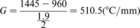
At the end of the crystal growth stage, there is a short lived mushy zone between both sides of the shell. The growth fronts of the columnar grains will be subjected to a force as the two solidifying shells contact each other. Because the ductility of steels is poor at temperatures close to their solidification point, 16,17 the columnar growth fronts break into fragments that finally grow into equiaxed grains. It has been reported that negative segregation could be caused by the phenomenon that the mushy state steel with concentrated solutes was squeezed out, when two shells encountered and began to be reduced by two rolls. 11,18 The contact force in the centre of the strip would disappear after the solidification is completed.
Below the solidification end point, the strip is in the hot rolling stage and rolling forces acting on it gradually increase as the gap between the rolls decreases. The force analysis is shown on the right of Fig. 4. Friction is neglected because the in situ grown shells have the same speed as the roll face. It is clear that the rolling forces, which are perpendicular to the roll surface and at an angle θ with the horizontal, are the main reason for the strip deformation.
In traditional hot rolling process, the largest deformation is always in the surface layer. However, the deformation distribution in the TRC strip is completely different because there is a large temperature gradient in the thickness direction of the strip, as shown above. Meanwhile, at high temperatures, a significant change in the ductility is noticed for both silicon steel and low carbon steel. 16,17 As the temperature decreases, the ductility increases first and finally decreases. It reaches the peak value at about 1150–1250°C. Therefore, the easily deformed area for both sides of the strip corresponds to this temperature zone. It can be explained why the most serious deformation across the strip thickness is located at the zone (s = 0.25–0.65) in the present work.
Conclusions
Strips (1.6 mm) of Fe–6.5wt-%Si alloy were prepared by TRC. The influence of mechanical factors on the solidification structure of the strips was investigated. The strip mainly consists of columnar and equiaxed grains. The plastic deformation of the strip is inhomogeneous in the thickness direction. The most significant deformation is located at a certain depth from the strip surface, and the columnar grains tilt in the direction opposite to the CD. The mechanical factors play a significant role in the formation of the strip structure during the TRC process. As the two solidifying shells contact each other at the end of solidification, the columnar growth fronts break into fragments, which finally grow into equiaxed grains. At the hot rolling stage, the inhomogeneous deformation of the strip is attributed to the reason that the ductility of the alloy is sensitive to temperature. There is a large temperature gradient in the thickness direction of the strip, which can be up to 510°C mm− 1.
Footnotes
Acknowledgements
This work is part of a research programme financed by Hi-Tech Research and Development Program (863) of China (no. 2012AA03A506).