
Abstract
The characteristics and kinetics of iron oxide reduction by carbon in biomass composites were studied. Iron oxide can be reduced by biomass very rapidly, and the degree of metallisation and reduction increases with temperature. Iron oxide reduction by carbon in biomass can be divided into two stages: reduction by volatile carbon followed by reduction by non-volatile carbon. The reduction times of the two stages both decrease with increasing temperature. The first reduction is controlled by gas diffusion, whereas the second stage is dominated by carbon gasification.
Introduction
Ironmaking is an energy demanding process, consuming ∼70% of the total energy in the steel company. 1 Most of the heat required for molten iron production is typically provided by coke combustion, but the coke price keeps rising with the decreased coking coal resources. In addition, ironmaking is also one of the largest industrial emitters of carbon dioxide in the world. It can be anticipated that the CO2 emissions from the steel industry will increase further along with the growth of crude iron production, unless new energy resources are valorised and the current ironmaking process is significant upgraded.
Biomass is a carbon neutral and renewable source. Biomass utilisation for energy in the industry can reduce CO2 emissions and fossil energy consumption. Abundance of biomass sources makes it possible for the substitution of coke and coal in the ironmaking process. Biomass utilisations in iron ore sintering, blast furnace, and some new ironmaking process have been reported. 2–5 In the sintering, biomass can reduce the amount of coke breeze and SO2 emission without affecting the quality of sinter. 2,3 Biomass can also reduce the amount of coke in the blast furnace. 4 (i) Charcoal can replace coke directly inside the blast furnace. (ii) Iron ore composite with biomass char can reduce coke indirectly in the furnace. 5 (iii) Biomass synthetic natural gas, bio-oil and biomass powder can be injected into the blast furnace as natural gas, heavy oil and coal powder. 6–9
In addition to applications in the traditional ironmaking process, biomass is also used in some new technologies, such as two-step direct reduction ironmaking technology. 10,11 Iron ore and biomass pellets are used as the raw materials in this process and transformed into sponge iron at last. In addition, biomass is also used as a reducing agent in a fluidised bed or fixed bed. 12–14 It has been proved that iron ore can be reduced to iron by biomass in a fluidised bed or fixed bed, which are all short ironmaking processes and are of low energy consumption and low pollution compared with the blast furnace process. It can be expected that ironmaking with biomass will be developed rapidly in the future.
However, to the best of our knowledge, studies in this area are mainly on the feasibility of iron ore reduction by biomass. To better improve the existing bio-ironmaking (ironmaking based on biomass) technology and develop new technology, reduction characteristics and kinetics of iron oxide by biomass need to be known. However, few studies have ever been published on this matter. It is well known that iron ore can be reduced by the hydrogen and carbon in biomass. This work aims at studying the reduction characteristic and kinetics of iron oxide powder by biomass carbon, which potentially helps to develop new ironmaking technology. The hydrogen reduction and their respective contribution to the reduction will be studied in the next work.
Experimental
Materials
The raw materials for the experiments were pine sawdust (PS) and hematite reagent powder. PS was provided by one timber mill in the Changping district in Beijing, China. The particle diameters were 0.15–0.45 mm, and the proximate and ultimate analysis was given in Table 1. Hematite reagent powder was provided by Sinopharm Chemical Reagent Beijing Co. Ltd. The content of Fe2O3 in hematite reagent powder was >99.0%. Before the experiment, these samples were dried in oven at 358 K for 1 h, and then were mixed and stored in desiccators for test.
Properties of PS/mass-%
Biomass–iron oxide (BI) composites were mixed from PS and hematite reagent powder in a tablet compression machine under a uniaxial pressure of 20 MPa (matrix with 20 mm in diameter and 50 mm in height). The mass ratio between PS and hematite powder in BI was 1:1. PS singly used in the experiment was also compacted under the same situation as BI. In order to keep the same amount of biomass used in each test, the mass of BI was twice as that of PS.
Methods
A schematic diagram of the experimental system is shown in Fig. 1. A SiC resistance furnace was used for heating with a maximum working temperature of 1673 ± 2 K. During the experiment, N2 was introduced at the rate of 6 L min− 1, and the temperature was kept constant for 10 min after the temperature in the reactor reached the preset temperature (1073, 1223, 1373 and 1523 K). The sample was put into a basket and fed into the reactor centre.
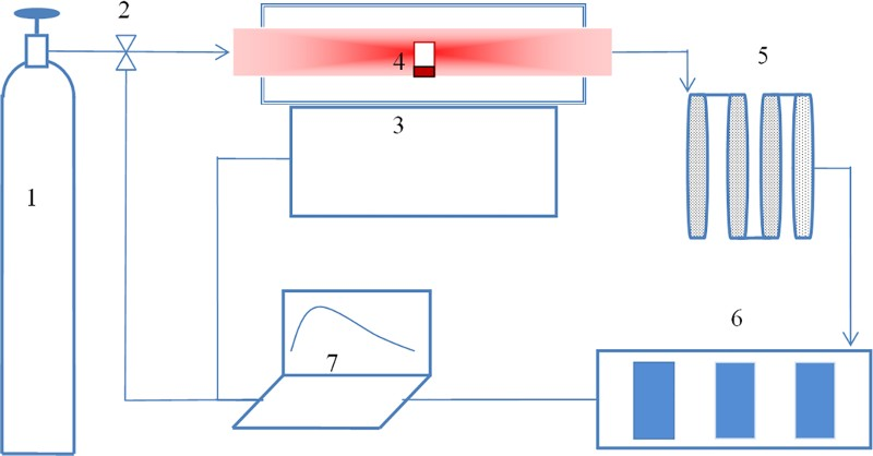
Schematic diagram of experimental apparatus (1, N2 bottle; 2, mass flow controller; 3, electric furnace; 4, samples; 5, filter and cold trap; 6, gas analyser; 7, computer)
The generated gases during sample heating were collected into the gas analyser via a filter and cold trap. Fine particles and agglomerations in generated gas, such as soot, tar and water, were removed by the filter and the cold trap respectively. CO and CO2 concentrations of generated gases were measured continuously by the gas analyser. After 10 min of sample test, the CO concentration of generated gases reached 0, so the test time of each sample was set at 10 min. After the test, the final metallisation and reduction degrees of BI were determined by chemical analysis.
In the previous work, reduction kinetics were generally studied by thermal gravimetric method. 15,16 The reacted fraction was obtained from the weight changes of sample. However, this method cannot be used in this work owing to the influence of high hydrogen content and volatile content on the weight changes. Exhaust gas analysis method was used in the study.
To ensure the reproducibility of test results, each test was repeated for three times. The relative error was calculated based on the total amount of CO and CO2. The relative error was controlled to < 10%. If the relative error was bigger than 10%, one more repetition test would be conducted. The test whose total amount was closest to the average value was selected to compare the tests among different temperatures.
Assumptions
In order to facilitate the analysis of the reduction kinetics, assumptions on the reduction process of BI are as follows. (i) First, there is a uniform distribution of particles of chemicals inside BI. (ii) Second, many reactions occur in BI in the high temperature process, such as biomass pyrolysis and iron oxide reduction. The focus of this paper is to study the reduction of iron oxide. Reactions and processes related to the reduction are considered, and any reactions unrelated to reduction are ignored. (iii) Third, H2 and CO can affect each other due to the water gas shift reaction, but H2 is converted into H2O again after the reduction. The reactions are as follows: CO+H2O → H2 + CO2; H2 + Fe2O3 → Fe+H2O. The overall reaction of the above is as follows: CO+Fe2O3 → Fe+CO2. This phenomenon also occurred in the blast furnace. H2O plays the role of a catalyst for the carbon reduction. In this paper, H2O from biomass pyrolysis is also considered as a catalyst.
Results and discussion
Reduction analysis
The morphologies of BI at different temperatures are shown in Fig. 2b . The sample at 298 K in the figure is the one without reduction. As can be seen from the size of samples, the volume of BI reduces with temperature. Iron with metallic luster can be observed at high temperature, especially at 1373 and 1523 K, from which it is inferred that iron oxide can be reduced by biomass in BI. In order to investigate the metallic iron content in the sample, the samples after the reaction were characterised through chemical analysis.
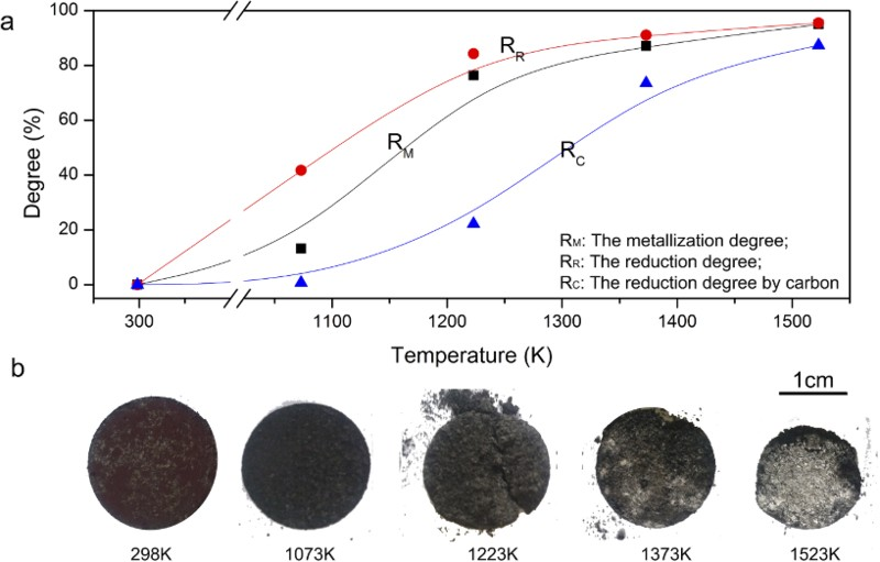
Reduction degree and morphologies of BI
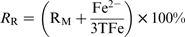
The metallisation degree (R
M) and the reduction degree (R
R) of samples were calculated according to equations (1) and (2):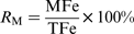
Analysis of CO2 and CO emissions
The main carbon based gases produced during biomass pyrolysis are CO2, CO, CH4 and others. 14 Iron oxide can be only reduced by CO, and the CO gas converts into CO2 after the reduction. Other carbonaceous substances (such as fixed carbon) are also converted into CO and CO2 after the reduction of iron oxide. So the reduction reaction can be studied by the change of CO and CO2.
The emissions of CO2 and CO at different temperatures are illustrated in Fig. 3. Different temperatures contribute to different gas contents. At 1073 K, the gas contents in the evolved gases from PS and BI are almost the same, which both reach a maximum level after 75 s. The maximum of CO yield is 2.8 × 10− 6 mol s− 1, much larger than that of CO2 (1.2 × 10− 6 mol s− 1), which shows that hematite is nearly not reduced by carbon at this temperature. The reason might be that the reduction rate was very slow at this low temperature, whereas the CO gas escaped too fast to reduce iron oxide. However, the degree of metallisation of BI reaches a high level of 25.77% at this temperature due to the existence of hydrogen and the lower reduction temperature of hydrogen than that of carbon. 21,22 In addition, compared with other temperatures in Fig. 3b–d , only one reduction stage exists at this temperature.
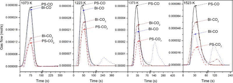
CO2 and CO emission of BI and PS at different temperatures
At 1223, 1373 and 1523 K, the CO2 and CO curves of BI are different from those of PS. These differences are caused by the reduction of carbon in BI. According to the CO curves of BI, the reduction of carbon occurs in two stages. At the first stage, CO content in the gases that evolved from BI is lower than that from PS at the same time and temperature because some CO gas has been involved in the reduction of iron oxide, which leads to a higher CO2 content in the evolved gases from BI than that from PS. This proves the reduction of iron oxide by CO gas, and the reaction equation is proposed as equation (3).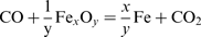
At the second stage, CO content in the evolved gases from BI is much higher than that from PS (almost zero). However, for BI, the highest CO yield reaches 2.6 × 10− 6 mol s− 1 at 1523 K, and the similar phenomenon was observed by Ueki and his co-worker
14
before. They found that the conversion ratio of biomass into CO and CO2 in biomass–iron oxide mixture reached >95%, but the conversion ratio of biomass in sole biomass only was ∼40%, strongly supporting that strong reduction occurred in BI. Other carbonaceous materials (not CO) also involves in the reduction. Without iron oxide, fast pyrolysis of biomass yields up to 75 wt-% bio-oil.
17
Fast pyrolysis is generally conducted at the temperatures from 723 to 923 K, while the reduction of iron oxide occurs at 1173–1523 K. At high temperature, bio-oil conversion into low molecular weight products may occur through three pathways. First, bio-oil might convert into gas in the first reduction stage. Second, new bio-oil different from pyrolysis bio-oil is produced in the reaction of BI, and then this new bio-oil reacts with iron oxide in the second reduction. Third, the previous two reactions occur simultaneously. If the bio-oil converts into gas, carbonaceous gas (CO) reduces iron oxide as equation (3). If the bio-oil does not convert into gas, this oil will reduce iron oxide as equation (4). Besides the oil carbon, other carbonaceous materials also include some fixed carbon. In this work, this carbonaceous material (oil and fixed carbon) is marked as Co. The reaction equation is shown as equation (4).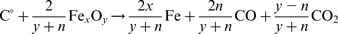
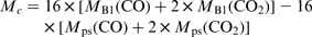
In order to further explore the contribution of carbon to the reduction, the total amount of carbonaceous gas is calculated by the integration method. The results are shown in Fig. 4. The total amount of BI is different from that of PS. The reaction rate will be calculated in the ‘Reduction of iron oxide by volatile carbon’ and ‘Reduction of iron oxide by non-volatile carbon’ sections according to this difference. Now, the contribution of carbon to the reduction is discussed first. According to equations (3) and (4), the oxygen in iron oxide is transmitted to carbonaceous gas by the carbon reduction. So the oxygen loss of iron oxide is exhibited by the change of carbonaceous gas between PS and BI.
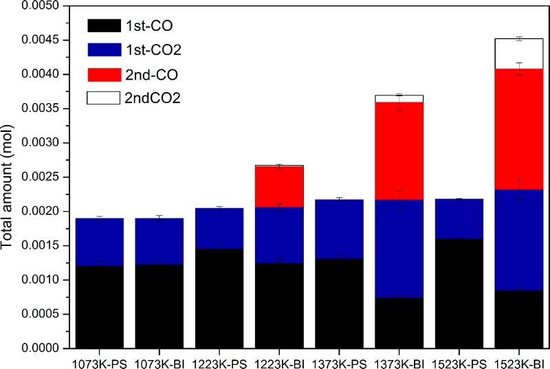
Total amount of CO and CO2 at different temperatures
The reduction degree by carbon (R
C) is calculated according to equation (5):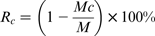
Reduction of iron oxide by volatile carbon
Definition of reduction rate and reacted fraction
As described in the previous section, the reduction of iron oxide by biomass carbon is divided into two stages: volatile carbon reduction and non-volatile carbon reduction. The reduction kinetics of each stage will be detailed in this part.
In this paper, the reduction rate of iron oxide by biomass carbon was characterised through the analysis of gas contents in the exhaust. For the reduction of volatile carbon, the reaction occurs as equation (3). From equation (3), the reaction rate is determined by detecting the change of CO content. In addition, the change is obtained by comparing the CO contents in the evolved gas from PS and BI. Since CO content in the exhausted gases from BI is lower than that from PS, the difference of them is exact part involved in the reduction of iron oxides. The reduction rate of volatile carbon (V
vc) is defined as equation (7):
Fig. 5a shows the reduction rate of volatile carbon with temperature. The reduction rate changes as the reaction proceeds, and the change trends are different at the different temperatures. It is inferred from Fig. 5a that the reaction times are ∼100, 50 and 40 s at 1223, 1373 and 1523 K respectively, which indicates that temperature exerted a key influence on the reaction time. The reduction rate of volatile carbon increases with temperature elevation. At each temperature point, the reduction rate increases first and then decreases as the reaction proceeded, especially at 1373 and 1523 K. The maximum CO content is 2.2 × 10− 6 mol s− 1 and 4.0 × 10− 6 mol s− 1 at these two temperatures.
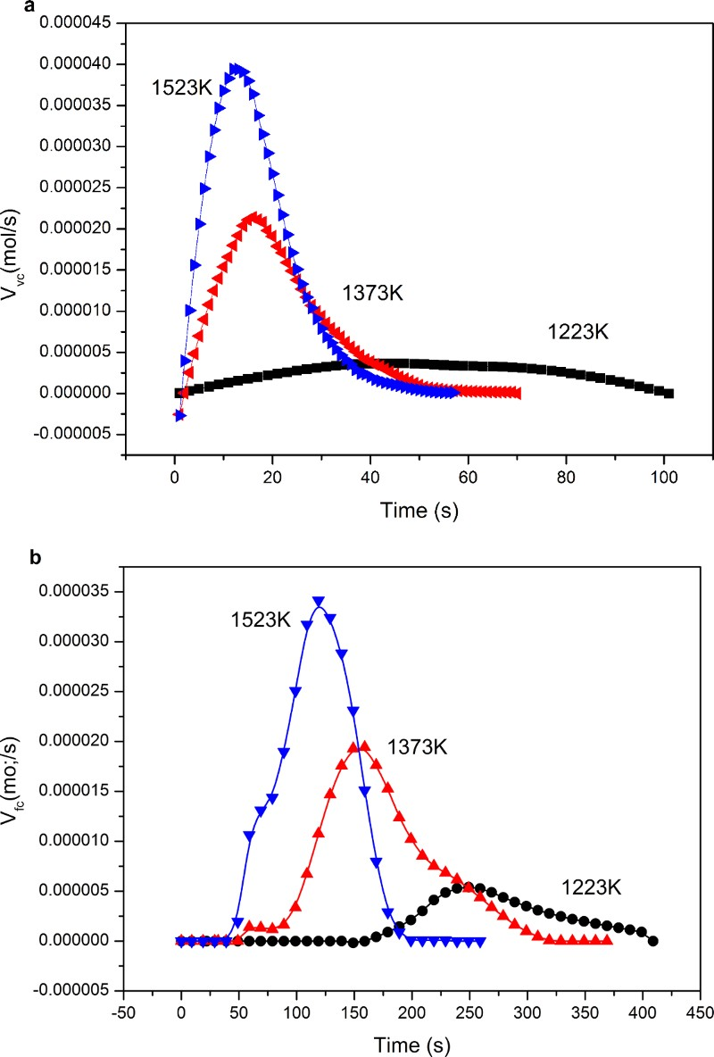
Reduction rate of a volatile carbon and b non-volatile carbon
The reacted fraction R
vc of the reduction of volatile carbon is defined as equation (8):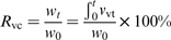
The relation between the reacted fraction R vc and time t is obtained through equation (8), and the results are shown in Fig. 6a . With elevation of temperature, the reaction fraction increased. The time for R vc to reach its maximum value at 1523 K is ∼40 s, shortest among the values, while at 1223 K, the reaction time becomes 100 s, which is the longest among all the values.
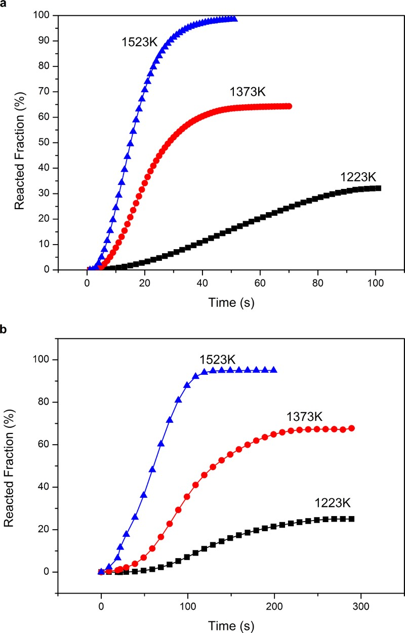
Reacted fraction of a volatile carbon and b non-volatile carbon at different temperatures during reduction
The reduction process by volatile carbon is a gas–solid reaction, and the main reaction process includes the following: (a) The gas diffuses through the porous solid product layer of iron to the boundary layer of Fe
x
O
y
(b) CO gas reacts with Fe
x
O
y
and CO2 is generated in the reaction interface (c) The reoxidation of Fe
x
O
y
by CO2
(d) CO2 goes through the porous solid product layer of iron to the surface.
The corresponding process is shown in Fig. 7. In addition, the possible rate determining steps (RDSs) during the reduction process by volatile carbon include the following
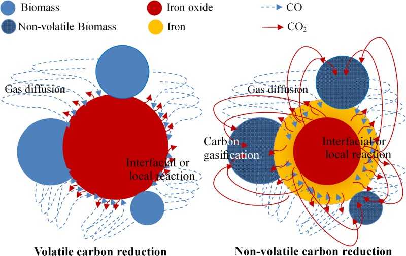
Schematic of reduction of iron ore by biomass carbon
(a) Diffusion of gas between the solid particles (b) The interfacial (or local) reaction
Kinetics analysis
The experimental data are analysed by different models with the assumed RDS. If the reduction by volatile carbon is controlled by the interfacial (or local) reaction, the reduction rate can be expressed by Mckewan equation: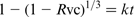
The experimental results at 1223–1523 K are analysed according to the above equations (9, 10). The rate constant k can be obtained from the results. Given the rate constant k for the reduction reaction at different temperatures, the activation energy is calculated according to the Arrhenius equations (11, 12):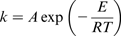
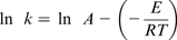
Relationship between ln k and 1/T of a volatile carbon and b non-volatile carbon
Activation energy E of volatile carbon reduction
Reduction of iron oxide by non-volatile carbon
Definition of reduction rate and reacted fraction
At the second stage, the reduction of non-volatile carbon occurs as equation (4). Through equation (4), the reaction rate can be determined by detecting the change of carbon in Co, which can be obtained by the CO and CO2 contents. According to the law of conservation of mass, the decrease of C is equal to the increase of CO and CO2. The reduction rate of non-volatile carbon (V
fc) is defined as equation (13):
The reacted fraction R
fc of the reduction of volatile carbon is defined as equation (14):

The relation between the reacted fraction R fc and time t is obtained by equation (14), as shown in Fig. 6b . The shortest time for R fc to reach its maximum value is 150 s at 1523 K, while the longest time is 250 s at 1223 K, confirming that temperature is an important factor for the reaction rate. Higher temperature contributes to faster reaction rate.
The reduction process by non-volatile carbon is different from that by volatile carbon. In previous studies on carbon based direct reduction of iron oxide, the reaction of carbon and iron oxide is considered to occur. The first step is the gasification of CO2 with fixed carbon, and the second step is the reduction of iron oxide by CO produced in the gasification.
18
As discussed in the ‘Reduction analysis’ section, the oil and fixed carbonaceous material are involved in the reduction. According to the previous studies, the amount of produced carbon monoxide in the gasification is much bigger than that in the pyrolysis,
19
and iron ore is very effective for CO2 gasification of woody biomass,
20
so the oil and fixed carbonaceous materials should also be involved in the gasification of carbon. After the gasification, iron oxide is reduced by the CO gas produced by non-volatile carbon gasification. The reactions are shown as equations (16) and (17). (e) The CO2 gas diffuses through the porous solid product layer of iron to the boundary layer of non-volatile carbon (f) CO2 reacts with the non-volatile carbon with the evolution of CO
The corresponding process is displayed in Fig. 7. So one possible RDS during the reduction process by non-volatile carbon is added as well:
(c) Carbon gasification
Kinetics analysis
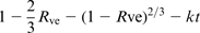
If the reduction by non-volatile carbon is controlled by the gasification of carbon, the reduction rate can be expressed as equation (18).
Activation energy E of non-volatile carbon reduction
The activation energy for gas diffusion is 79.6 kJ mol− 1, and the activation energy for interfacial (or local) reaction is 134.6 kJ mol− 1. For carbon gasification, the activation energy increases to 149.5 kJ mol− 1, indicating that the gasification of carbon has great effects on the reduction. This could be because non-volatile carbon contains some complex structure organics, which is not easy to react with carbon dioxide. In addition, it can be concluded that carbon gasification is the reduction determining step for the non-volatile carbon reduction and the activation energy of the reduction is 149.5 kJ mol− 1.
A number of studies have been conducted on iron oxide reduction by different carbonaceous materials, and the kinetics results were very different. However, most studies suggested that carbon gasification is the RDS, no matter what reducing agent, such as coal, coke, graphite or charcoal, was used. 24 Our results are consistent with those previous studies. Alkali metal as the catalyst is usually used to increase the gasification of carbon, and it may favour the carbon gasification in biomass–iron oxide composites. Moreover, the activation energy of hematite powder reduction by amorphous carbon, graphite, coal, charcoal and coke ranges from 293 to 335 kJ mol− 1, 24 much higher than that for hematite powder reduction by biomass (149.5 kJ mol− 1). This indicates that the reduction by biomass is much easier than that by other carbonaceous materials, and the rate of metallisation at 1373 K for only 10 min reaches 87.12%.
Industry prospect of bio-ironmaking
According to the above discussions, it has been found that iron oxide can be reduced by biomass and the reduction is very strong at the temperatures above 1373 K. At 1373 K, the metallisation rate of BI was 87.12%. Similar metallisation rates of iron ore and coal pellet (ICP) were found in our previous work at the same temperature. 23 However, the reduction time of ICP was 45 min, which was much longer than that for the reduction of BI (5 min). For a faster reduction rate of ICP, higher temperature over 1373 K is necessary. This indicated that iron oxide can be reduced to a greater extent by biomass than by coal, with a lower temperature of reduction by biomass than by coal. This is a significant advantage of using biomass in ironmaking as a reduction agent, for reducing the reduction temperature and saving energy.
Moreover, biomass is a renewable energy source with one most remarkable feature of reducing the net carbon dioxide emission through the carbon recirculation, and the use of biomass has broad prospects for the ironmaking processes. For example, the rotary hearth furnace (RHF) as one of the direct reduction processes has been well developed in recent years. ICP is a kind of important raw material of RHF and biomass can take the replace of the coal in ICP and be made into iron ore and biomass pellet, which can be used in RHF directly. In addition, iron ore and biomass pellet can also be used in other ironmaking processes if their physical appearances (such as mechanical strength) meet the production requirements. In addition, some new technologies could be developed according to the reduction characteristic of iron oxide by biomass in the future.
Conclusions
Carbon reduction characteristic and kinetics of iron oxide by biomass have been investigated, with the following conclusions: (i) Iron oxide can be reduced by biomass very rapidly in biomass–iron oxide composites. The metallisation degree, reduction rate and reduction degree of the composites increase with increasing temperature. At 1523 K, the metallisation of 94.96% and reduction degree of 95.54% took only 190 s. (ii) Iron oxide reduction by carbon can be divided into two stages: the first stage is the reduction by volatile carbon and the second stage is the reduction process by non-volatile carbon. The reduction times for the two stages both decreased with increasing temperature, and the time for the reduction in the first stage was much shorter than that in the second stage at 1523 K. (iii) The reduction rates in the two stages are controlled by the gas diffusion and carbon gasification respectively. The reduction in the first stage with an activation energy of 184.5 kJ mol− 1 is more difficult than that in the second stage with an activation energy of 149.5 kJ mol− 1. (iv) Renewable biomass can replace the coal in iron ore and coal pellets for direct reduction ironmaking with the benefits of reducing the reduction temperature, saving energy and reducing the net carbon dioxide emissions.
Footnotes
Acknowledgement
This work was financially supported by National Natural Science Foundation of China (No. 51234008 and No. 51574024) and Fundamental Research Funds for the Central Universities (FRF-TP-14-111A2).