
Abstract
The possibility to reduce clogging in the submerged entry nozzle when casting Al killed low carbon steel has been evaluated. The coating materials have been tested in laboratory trials and pilot plant trials. Totally, two mixes of the coating material have been tested, containing 4.8 and 9.1% CaTiO3 mixed with yttria stabilised zirconia powder. The chemical composition was analysed using a field emission gun–scanning electron microscopy equipped with energy dispersive X-ray spectrometry. The major result showed that alumina reacted with CaTiO3 in the temperature interval from 1550 to 1600°C. In addition, the clogging ratio showed a decreased clogging tendency for coated nozzles compared to standard nozzles. In addition, the results showed that an approximately three times higher steel mass could be teemed through the coated nozzles before clogging occurred compared to trials with uncoated standard nozzles. Overall, it is concluded that plasma sprayed CaTiO3 coatings can reduce the clogging tendency during the continuous casting process.
List of symbols
– constant
– pressure
– molten steel density
– acceleration due to gravity
– vertical distance
– velocity
– theoretical mass teeming rate
– nozzle outlet cross-sectional area
– vertical distance between nozzle and liquid bath upper surface
– nozzle height
– mean value of the steel mass logged on the scale
– time
– noise reduced mean value of the measured mass teeming rate
– clogging factor
Introduction
Submerged entry nozzles (SENs) are used in the continuous casting process to protect the molten steel from oxidation and to achieve optimal fluid flow conditions from a tundish to a mould. 1–4 During casting of Al killed steel, clogging of aluminium oxide, titanium nitride and calcium sulphide inside the SEN has a large effect on the slab quality, representing a potential source of surface defects in free machining and stainless steel products. 5,6
Clusters attaching to the internal wall will result in clogging of the nozzle and thereby a decreased casting productivity. 4–6 In addition, flushing of these accretions causes entrapment of inclusions that eventually become sources of macroinclusions in the final products. Upon rolling, the macroinclusions appear as designated slivers on the rolled sheet's surface. 3–5,7 Overall, it should be noted that aluminium is added to deoxidise the steel melt and that it therefore is very difficult to prevent Al2O3 accretions in the SEN. 5
The aim of this study is to evaluate if clogging can be prevented or reduced, when using CaTiO3 plasma sprayed coatings of the SEN's inlet, when casting Al killed low carbon steel. Thermodynamically, a formation of liquid calcium aluminates takes place when alumina in the molten steel reacts with CaTiO3. This occurs according to reactions (A)–(C)
5,8
: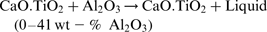
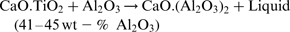

From the phase diagram of the CaTiO3–Al2O3 system in Fig. 1, it can be seen that the liquidus temperature of Al2O3 decreases with an increased CaTiO3 concentration. 5,8 Thus, the steel flow through the SEN will remove the liquid Al2O3–CaO from the SEN's internal wall at a temperature of 1600°C. 5,8
CaTiO3–Al2O3 phase diagram and eutectic point is at 41 wt-% Al2O3 and 1580°C 8
The formation of a liquid Al2O3–CaO phase has been evaluated by using both laboratory experiments and pilot plant trials. The laboratory experiments were performed to establish the formation of a liquid phase between CaTiO3 and Al2O3 by heating of a CaTiO3 powder in alumina crucibles. The suitability of CaTiO3 as a coating material was further evaluated utilising pilot plant trials with plasma sprayed nozzles. 9,10
To reduce clogging at the steel/ceramic interface, CaZrO3 and CaTiO3–ZrO2 materials have been suggested as suitable materials. 3,11,12 Therefore, the coating material in the pilot plant trials consisted of an yttria stabilised zirconia (YSZ) powder mixed with a CaTiO3 powder. The addition of YSZ enabled plasma spraying of the coating and contributed to a better adhesion between the coating and the RBM. In addition, ZrO2 is one of the most important high index materials for optical coatings. The produced thin films have been found to have outstanding thermal, mechanical and electrical properties. 13
YSZ have been stabilised at a high temperature (1100–2680°C). Therefore, the phase transition in pure ZrO2 from a tetragonal (1100°C) to a monoclinic phase (25°C) is avoided. 13 This phase transition is unwanted due to a 3–5% volume expansion, which can result in crack formations in ZrO2 coatings. In addition, thin films of YSZ have a good corrosion resistance, chemical durability, optical properties without a negative volume expansion and low thermal conductivity. 13
Background
Nozzle blockage occurs due to different factors such as poor steel cleanliness, steel temperature, shape of the nozzle, steel flow speed, and purity and stability of the refractory base material (RBM). 3,7,14,15 The RBM in the SEN commonly contains Al2O3–C, and during preheating of the SEN, decarburisation of the surface is common due to an increased oxygen activity near the inner wall. This results in a formation of an alumina layer on the SEN's internal surface, which consists of a precipitated accretion of non-metallic inclusions. 1,2,5,6 Molten steel is ejected from the space between the Al2O3 inclusions by the action of interfacial tension when the distance between the inclusions is ≤ 20 μm, since Al2O3 is almost not wetted by the steel. 3 Hence, a network of Al2O3 inclusions forms at the RBM/steel interface. 3
The build-up causing clogging has been observed to consist of several layers. First, the decarburised layer in the RBM, where the first deposit layer is formed, consists of Al2O3 particles. The second deposit layer has been observed to consist of Al2O3, SiO2 and alkalines. 15 In addition, the morphology of the Al2O3 build-up was studied by Ogibayashi, 3 who reported that two different networks could be observed. The build-up consisted of powdery alumina particles with voids, and the steel contained Al2O3 clusters. The other morphology was an Al2O3 network containing fine metal particles inside. 3 In addition, the deposition of the build-up has found to be located at the entrance of the SEN. 3,14,16 The high amount of Al2O3 clusters in the build-up has also been found to correlate to a decreased teeming rate. 16
To reduce clogging, argon gas injection into the SEN can be used. However, if the argon flow rate is excessively large, there is a risk that gas bubbles will disturb the molten steel surface and causes entrainment of the mould powder into the steel. 3,17 Another approach to reduce the clogging during casting of Al killed steels is to use calcium treatment to transform the solid Al2O3 inclusions into liquid Al2O3–CaO inclusions. 18,19 Thereafter, the inclusions are transported to the steel/slag interface in the ladle, tundish or continuous casting mould. 18 An excessive amount of calcium treatment in the ladle or tundish cannot act as a buffer for reoxidation, which takes place in the mould. Therefore, it can be difficult to predict a satisfactory Ca amount for longer casting times. 19,20 In steel grades containing levels above 0.012% S, CaS inclusions will form instead of the desired liquid Al2O3–CaO inclusions. 21
Different materials such as Al2O3–C, SiO2, MgO, ZrO2 and Al2O3 have been evaluated as possible RBM to reduce clogging when casting Al killed steels at temperatures of 1550°C. 2 For Al2O3–C, the molten steel was found to penetrate into the RBM. 2 When using fused SiO2, it was found to transform into cristobalite, which resulted in a crack formation due to the high temperature. 2 No steel was found to have penetrated into the MgO or ZrO2 RBM. However, the MgO inclusions were decomposed and the inclusions were sintered onto both the two RBMs. 2 In addition, the Al2O3–C RBM was plasma coated with Al2O3. The interaction between the molten steel and RBM could not be prevented. In addition, no interaction between the molten steel and RBM was observed when the coating material was made denser at a higher temperature. 2 In addition, clogging tests showed similar clogging resistances for nozzles made of MgO, ZrO2 and Al2O3 RBM. 22
RBM consisting of CaZrO3–C mixed with different amounts of non-hydrating CaO was tested by Okumura et al. 17 Specimens that contained a 30% non-hydrating CaO was fully eroded in contact with molten steel. In addition, erosion tests by Ramacciotti and Marino 20 showed no attack on CaO RBM by Al killed steel after a 30 min exposure time. CaO is not stable in a metallurgical process, and hydration is a problem when CaO loses its strength and undergoes a volumetric expansion. This results in cracks in the CaO coatings. 7,11,17,20 To diminish hydration, the CaO can be stabilised with ZrO2. 5,7,11,23,24 According to phase diagram studies by Murakami et al., 11 a CaO saturated CaZrO3 compound is the optimal nozzle composition. When this compound is in contact with Al2O3, a liquid phase will be formed at 1600°C. In addition, Tuttle et al. 5 carried out laboratory trials where CaZrO3 and CaTiO3 powders were pressed and sintered into RBM. Al2O3 inclusions were found to react with the RBM. However, only the reaction with CaTiO3 resulted in the formation of a liquid phase. 5
An addition of 20–40 mass-% TiO2 in the CaO–Al2O3 system has been found to decrease the liquidus temperature. 25 Moreover, CaTiO3 nozzles have been proven to outperform nozzles made of Al2O3–C, CaZrO3 and 2:1 CaTiO3–CaZrO3 in casting simulations. 7 Thus, by combining CaTiO3 with CaZrO3, it has been suggested that the material will have a better wear resistance compared to if the compounds are used separately. 12
Clogging can be reduced either by grain refiners or by inhibiting the reaction mechanism at the RBM/steel interface. 4 To obtain an optimal prevention of clogging, these measures should be combined to obtain a high steel cleanliness. This is due to that the reaction mechanisms at the RBM/steel interface will lead to the formation of more Al2O3 inclusions in the molten steel. 15
A limiting factor for CaO containing RBMs has been the ability to transport the CaO to the RBM/steel interface. If a coating is used, the additive does not need to be transported through the RBM. 7 Therefore, coating of the SEN could serve as a potential protection against Al2O3 build-up on the SEN when casting Al killed steel grades. Overall, suitable coating materials for SENs must have a combination of a favourable wetting angle with steel, a reduced potential for thermochemical reactions, and a low permeability to gases. 5,23,24 In addition, the smooth surface that a coating provides will reduce vortices in the flow that causes alumina particles to move to the SEN's wall due to inertia forces where they can stick to the surface. 3 With atmospheric plasma spraying, the coatings will have an excellent reproducibility, 10 and this is a technique that can be used for coating of the SEN for an industrial implementation at a further stage. In this study, CaTiO3 has been evaluated as a potential coating material for casting Al killed steel grades sensitive for clogging in the continuous casting process.
Experimental
Laboratory trials
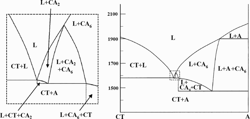
Experiments were conducted where CaTiO3 powders (99 wt-% pure, (325 mesh) were held in pure alumina crucibles in a Labmaster very high temperature graphite furnace (Fig. 2). The alumina crucible was placed into a graphite crucible and heated at a rate of 10°C min− 1. Here, the furnace temperature accuracy was ± 3°C.
Laboratory set-up for heating of CaTiO3 powder in Al2O3 crucibles in argon protected high temperature graphite furnace
In total, five different samples (C1–C5) were prepared, as presented in Table 1. Each sample consisted of ∼13 g CaTiO3 powder, which was placed in a 40 mm high crucible with a 30 mm outer diameter and a 3 mm thickness. The starting temperature was 400°C for all samples. In addition, a protective argon atmosphere with a flow rate of ∼4 L min− 1 was used.
Presentation of samples C1–C5 from laboratory trials
After the experiment, the crucibles were cooled during a 2–3 h period. Thereafter, the chemical composition of the samples was analysed using a field emission gun–scanning electron microscopy (FEG–SEM) equipped with an energy dispersive X-ray spectrometer (EDS).
Pilot plant trials—simulation of industrial casting process
In order to simulate the gap between the stopper rod and the SEN inlet for an industrial casting set-up, a 600 Hz induction furnace with a nominal melt size of 600 kg and an Al2O3 lining were used. During the trials, the upper surface of the steel melt was protected by liquid argon to minimise reoxidation of steel. About 420 kg scrap was melted and additions of 3 kg FeSi and 60 g Al were made 35 and 5 min before the start of teeming respectively.
The aim was to evaluate if the Al killed low alloyed carbon steel would react with the plasma coating and to evaluate if the clogging could be reduced. If the coating material reacts with the molten steel, this will results in less clogging when accretions does not attach to the nozzle wall. Since the nozzle inner diameter does not decrease, the teemed steel mass through the nozzles will not decrease either.
Three ZrO2 RBM nozzles were plasma sprayed with two different coating compositions. The coatings contained 100 g YSZ powder mixed with 9.1% CaTiO3 for nozzles N2 and N3, and 4.8% CaTiO3 for nozzle N4 of CaTiO3. The CaTiO3 powder was 99 wt-% pure and had a very fine grain size of (325 mesh. About 25–35 g of the powder mixing was consumed for each nozzle. The nozzles were plasma sprayed in air atmosphere after being heated up to 300°C. The powder was fed into a plasma beam and deposited onto the nozzle. 10 The nozzle dimension was limiting for the plasma beam, and the coating thickness varied between 200 and 400 μm. Owing to the nozzle geometry, the internal coating depth was 25 mm down from the inlet. In Fig. 3, the cross-section of the coated nozzle is presented. The results from the trials with nozzles N2–N4 were compared to an uncoated ZrO2 RBM reference nozzle N1.
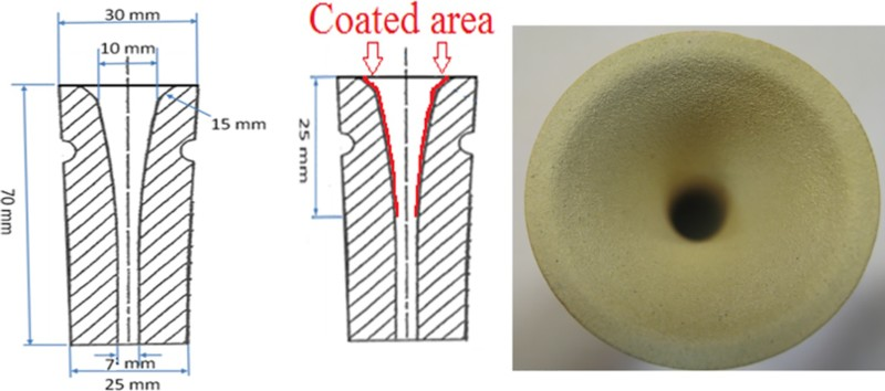
Cross-section of nozzle, and ∼25 mm of nozzle's internal wall could be plasma sprayed with 200–400 μm thick coating
During the experiments, the temperature in the nozzles and the steel melt were continuously monitored with 4 Rh–Pt thermocouples. In addition, the temperatures in the nozzles were kept higher than in the steel melt in the furnace to prevent clogging due to freezing during teeming. This is due to that if clogging did occur, then the clogging zone should consist of Al2O3 clusters and not to freezing of steel on the nozzle wall.
In total, five dual thickness steel samples were collected during each trial. Samples P1 and P2 were collected 6 and 2 min before the casting respectively. Samples P3–P5 were collected 1, 7 and 13 min after the start of casting respectively. The chemical composition of the steel and the inclusion composition were determined using optical emission spectroscopy, and the oxygen content was determined with pulse determination analysis (PDA).
During the trials, the molten steel was teemed into a mould on a scale, and the weight was measured continuously at a 1 Hz frequency. In Fig. 4, the set-up for the pilot plant trials is presented. In the experimental set-up, the open induction furnace is assumed to be the tundish from which the steel flows through a nozzle in the bottom. Owing to clogging, the nozzle's inner diameter decreased during the trials, and this was reflected on the teemed steel mass. During a clogging reaction, the teemed steel mass deviates from an ideal curve, representing a no clogging situation. After the trials, the sampled weight data were noised reduced and compared to an ideal teeming rate. The latter was calculated using the Bernoulli's equation, and in general form, the Bernoulli's equation can be expressed as follows: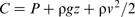
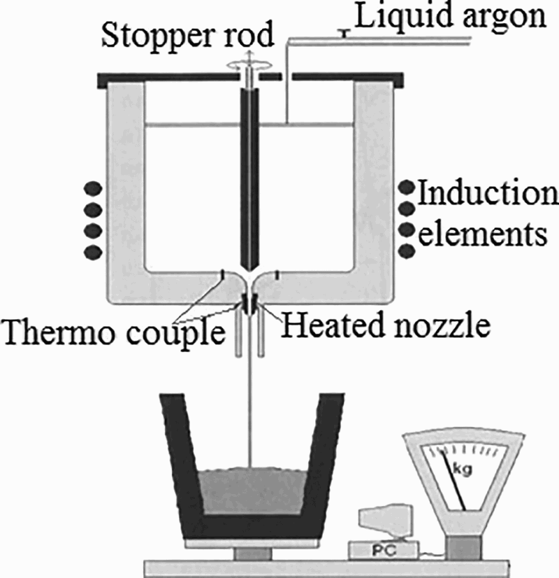
Pilot plant experimental set-up of induction furnace teeming molten steel through nozzles into mould placed on scale 14 ; teemed steel mass was continuously measured and logged; temperature was measured and controlled with thermocouples
Two points in the flowing steel melt are considered: one point at the free surface of the steel melt in the induction furnace, and it is compared with a point at the nozzle outlet. By applying equation (1) to the system, it is possible to calculate the liquid velocity at the nozzle outlet. According to the principle of continuity applied to an incompressible liquid, no fluid appears or disappears during the flow. Thus, the following relation is valid at every height position for the change of the theoretical mass teeming rate:
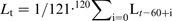

By using equation (4), the mass teeming rate in the pilot plant trials was compared to the theoretical mass teeming rate from equation (2). A deviation between data from equations (2) and (4) will appear if a nozzle starts to clog. Then, the teeming rate variation will not take place in an ideal manner from a hydrodynamic point of view. During the experiments, the different teeming rates for the theoretical and experimental values were compared. In addition, the amount of clogging was compared using the clogging factor ? suggested by Kojola et al.
23
:
The chemical compositions of the samples were conducted with a FEG-SEM equipped with an EDS. The solidified steel from within the nozzles was cut into smaller samples and ground, polished and etched. Samples from all nozzles were photographed, and the chemical composition was analysed using the backscatter mode.
Results and discussion
In total, 59 points from samples taken after heating of CaTiO3 powder in Al2O3 crucibles were studied. The amounts of oxygen, Al, Ca and Ti were analysed with SEM, and the results were compared with the phase diagram in Fig. 1 8 to establish the phases in the analysed points. The findings showed that 19 points corresponds to a solid phase, and 40 points to a liquid phase. In Table 2, evaluated phases from the chemical compositions in samples C1–C5 are presented.
Analysed points from samples C1–C5
The experiments were conducted in an argon atmosphere, and it was assumed that this was an inert system. For this reason, the elements Al, Ca and Ti were assumed to be in their oxide form.
In all evaluated samples, CaTiO3 had reacted with Al2O3 at temperatures between 1550 and 1600°C. Even though some evaluated points in the CaTiO3 + liquid phase region contained almost only CaTiO3, the analysed point was not pure. Therefore, it was assumed that the point contained a liquid phase.
For crucibles C1 and C2, the reaction was most distinguished, and the dwell time for C1 was only 12 min instead of 60 min. In addition, in some of the evaluated points in samples from crucibles C1 and C4, the element Ca was not detected. From C3, only four points were analysed with SEM. Overall, the SEM analyses of all evaluated samples showed that CaTiO3 had reacted with Al2O3. In comparison with the CaTiO3 and Al2O3 phase diagrams, the amount of Ca and Ti found in the Al2O3 crucible after heating indicated the formation of a liquid phase.
The reaction between CaTiO3 and Al2O3 to form a liquid phase during casting was further examined in the pilot plant trials. The molten steel was teemed through three CaTiO3–YSZ plasma sprayed nozzles N2–N4 and one reference nozzle N1. During the trials, the steel flow teemed out of the nozzles was observed. In the reference trial with nozzle N1, the teemed steel flow fluttered and splashed. The steel flow through the nozzle decreased, and at the end of the teeming, the steel was dripping from the nozzle. For the plasma coated nozzles N2–N4, the steel flow was observed to be calmer and steadier compared to the reference trial. Therefore, the casting could proceed longer before the teeming was stopped.
Data of the teemed steel masses for nozzles N1–N4 were compared with respect to deviation from the theoretical teemed steel mass (Fig. 5). The total teeming time was longer for the plasma sprayed nozzles. This resulted in an increase of the teemed steel mass with about three times before clogging compared to the reference trial.
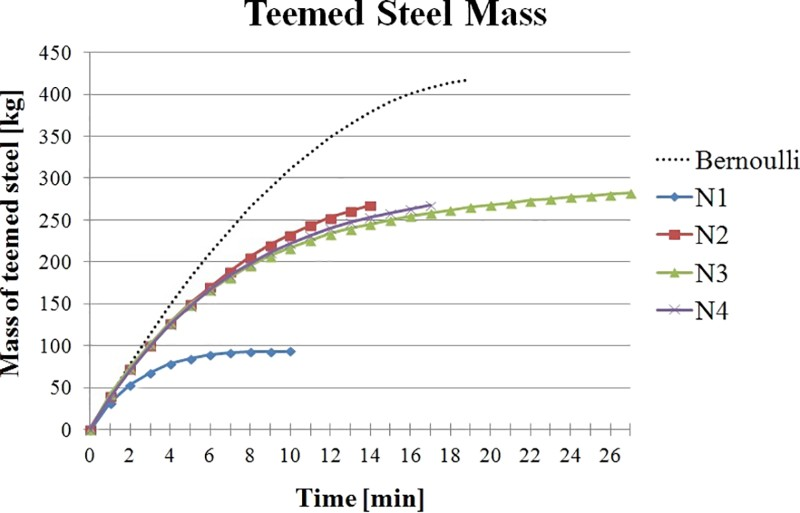
Actual teemed steel mass for all four nozzles compared with theoretical teemed steel mass through nozzles
The teemed steel masses before clogging in the nozzles were 53, 101, 103 and 100 kg for nozzles N1, N2, N3 and N4 respectively. In comparison to nozzle N1 (reference), an implementation of nozzles N2, N3 and N4 reduced the clogging tendency. In addition, the amount of teemed steel was observed to be higher for the coating containing 9.1% compared to the coating containing 4.8% CaTiO3.
In Fig. 6, the clogging factors for all nozzles are presented. The results show that the clogging factor was up to ∼1.3–1.5 times higher when casting without any coating in trial N1. The clogging factor was similar for nozzles N3 and N4, and nozzle N2 had the lowest clogging factor value. Therefore, the clogging was found to be reduced most when casting of nozzle N2 with a 9.1% CaTiO3 coating. However, since the clogging factors for nozzles N3 and N4 were similar and due to an uncertainty of 200 μm in the coating thicknesses, it cannot be concluded how much more the 9.1% CaTiO3 coating reduced the clogging in comparison to the 4.8% CaTiO3 coating. The probability for the coating to contain more CaTiO3 particles was higher for the 9.1% CaTiO3 coatings. The coating mixtures originally contained 100 g YSZ mixed with 5 and 10 g CaTiO3 respectively for the 4.8 and 9.1% CaTiO3 coatings. Only 25–35 g of the mixture were consumed in each nozzle's coating. Depending on the homogeneity on the mixing, the amounts of CaTiO3 in nozzles N3 and N4 can be similar. This could explain the similar clogging factor for the nozzles.
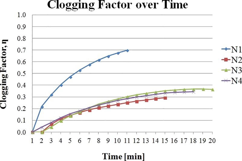
Clogging factor of nozzles, where η is 0 at start of teeming and 1 at complete clogging of nozzle
During the pilot plant trials, five dual thickness steel samples (P1–P5) were collected, and in Table 3, the analyses of the samples are presented (given in wt-%). For the reference nozzle N1, the Al content was 0.006–0.018 wt-% larger in sample P2 in comparison to corresponding data for the other nozzles. Sample P2 was collected ∼3 min after an Al addition to the steel melt before casting. Samples P3–P5 were collected after the start of teeming.
Steel compositions of dual thickness samples for nozzle N1–N4/wt-%
The element contents in the samples were even for respective nozzle. However, the average Si and Mn contents were lower for nozzle N1. In all samples, the Al content was found to decrease with an increased time. For trial N1, the Al content decreased with ∼0.030 wt-% between samples P3 and P4, as well as between samples P4 and P5. The corresponding decreases for the other nozzles were ∼0.010–0.020 wt-%. As the Al content in the lollipop samples decreased with time, the clogging tendency increased, although a high Al content will increase the clogging rate. 3 However, for the pilot plant trial, the 600 kg furnace was also the tundish. In an industrial case, the tundish will have a stable amount of molten steel during most of the teeming process. In the present trials, the level of molten steel decreased during the teeming in the pilot plant trials. Therefore, it can be assumed that the Al content in the melt decreased due to that the total amount of steel also decreased during teeming. When comparing these results to the results in Fig. 5, it is seen that after 2 min into the casting, the teemed steel mass started to deviate from the theoretical curve for all nozzles but to different extents. In total, the teemed steel mass increased with 1.89 times for 4.8% CaTiO3 coating. In the same way, the increase was 1.90 and 1.94 times for the 9.1% CaTiO3 coating.
In Table 4, the inclusion compositions in the samples determined by PDA are presented, given in wt-%. The Al2O3 inclusion content in the melt was higher in the reference experiment N1 compared in the experiments using plasma coated nozzles N2–N4. For nozzle N1 in comparison with N2–N4, the decrease of Al2O3 inclusions was 0.5–1.3 wt-% higher between samples P3 and P4. Between samples P4 and P5, the decrease was 0.4–3.3 wt-% higher for the N1 experiment compared to the coated nozzles N2–N4. Overall, the total amount of inclusions was almost the same for all nozzles.
Inclusion calculated by PDA technique/wt-%
The casting temperatures for the plasma sprayed nozzles for experiments N1, N2, N3 and N4 were 1532, 1565, 1552 and 1553°C respectively in the molten steel, and 1615, 1640, 1638 and 1646°C in the nozzle. Thus, the casting temperatures were 20–33°C lower in the furnace and nozzle for nozzle N1 in comparison to the other experiments. Previously, it has been found that the clogging factor over time is independent of the nozzle's temperature. In nozzle clogging experiments by Kojola et al., 23 clogging occurred at a constant rate for both cold and hot nozzles. It should be noticed that the clogging factor was always larger for cold nozzles than for hot nozzles, where the larger clogging factor was most likely due to an initial freezing on the nozzle's internal wall. 23 In addition, the temperature difference for the hot and cold nozzles was 300°C. 23 However, since the temperature difference in this study was only 20–33°C, it is not likely that the stronger clogging tendency in N1 compared to the coated nozzles (N2–N4) was due to an initial freezing. If the clogging would be caused by an initial freezing, SEM analyses would have shown an initial steel shell at the steel/nozzle interface and not accretions of Al2O3 clusters. 3 In addition, the clogging occurred at a constant rate for experiments N1–N4. Therefore, freezing can be ruled out as the dominating factor for the clogging. 14
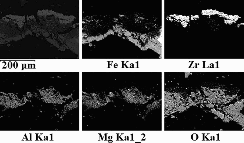
In the cross-section of nozzle N1, Al2O3 clusters had attached onto the nozzle wall, presented in the mapping from the FEG-SEM analysis in Fig. 7. Observation of nozzles N2–N4 showed that the CaTiO3–YSZ coating had reacted with the steel during casting. This was distinguished by visible clusters attached on the nozzle's inner wall. In Fig. 8, the inlets of all nozzles after teeming are presented. SEM analysis showed that the clusters contained Al and Ca in a steel matrix. However, no Ti was observed during the mapping with EDS. The content of Ca and Ti in the coating was low, and this made it difficult to detect those elements.
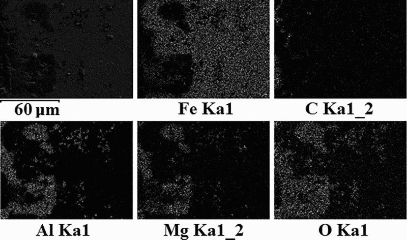
Mapping analysis of cross-section of nozzle N1 showing build-up consisting of Al, Mg and oxygen onto nozzle wall
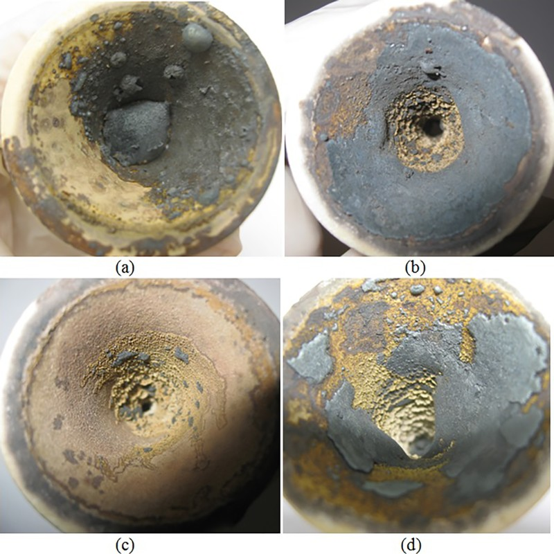
Nozzle inlet from above after casting in pilot plant trials: a N1; b N2; c N3; d N4
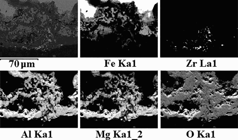
In the cross-section from the inlet into the nozzle N2, a network of Al2O3 was built up and attached to the coating. In addition, the measured thickness of the remaining coating material was up to 67 μm (Fig. 9). In Table 5, the chemical composition is presented.
Mapping analysis of cross-section of nozzle N2; elements displayed are Fe, Zr and build-up consisting of Al, Mg and oxygen; from upper part, remaining of coating can be observed by Zr content, which was measured up to thickness of ∼67 μm
Chemical analysis of cross-section; from nozzle N2
A cross-section from the middle of nozzle N3 is shown in Fig. 10. From the mapping, traces of Zr originating from the coating material have followed the steel flow down in the nozzle. In Table 6, the chemical composition is presented.
Mapping analysis of cross-section from middle of nozzle N3; elements displayed are iron, Zr and build-up consisting of Al, Mg and oxygen; elements from coating material can be observed by Zr content and was measured up to thickness of ∼19 μm
Chemical analysis of cross-section; from nozzle N3
In the SEM results for nozzle N4 in Fig. 11, it can be seen that a large amount of Zr is present at the steel/nozzle interface. The coating had reacted and been reduced to ∼30–40 μm in thickness. In Table 7, the chemical composition is presented.
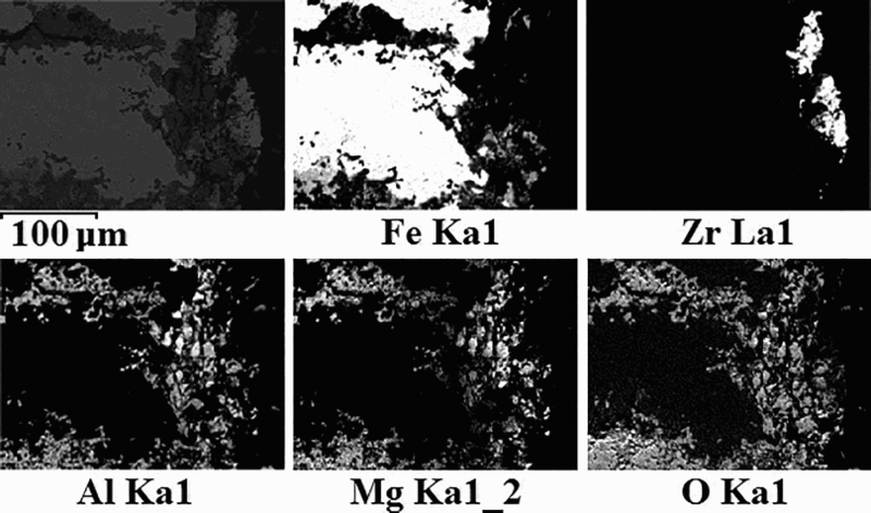
Mapping analysis of cross-section from middle of nozzle N4; elements displayed are iron, Zr and build-up containing Al, Mg and oxygen; thicknesses of two remaining parts of coating material were 28.93 and 37.24 μm, and lengths were 68.18 and 70.47 μm respectively from above
Chemical analysis of cross-section; from nozzle N4
The plasma sprayed coating was observed to be consumed during the casting, and it was thus found to be reactive. Findings of the remaining coating were observed in samples from all nozzles N2–N4. The original thickness was 200–400 μm, and the remainder of the coatings was measured as ∼70 μm. Consequently, this indicated that a reaction had taken place between CaTiO3 and Al2O3. Since the coating only was observed with SEM on a small surface, it is assumed that most of the coating was consumed during teeming and that it had reacted with Al2O3 inclusions in the melt.
The amount of CaTiO3 in the coating was very low, and it was difficult to locate any CaTiO3 that originated from the coating in the solidified steel in the nozzle and in the remaining of the coating. However, if the Al2O3 did react with CaTiO3 to form liquid inclusions, these would not be present in the solidified steel. Instead, they would simply follow the molten steel flow into the mould. Moreover, the SEM results clearly show that even though the nozzles N2–N4 were plasma coated, a network of Al2O3 cluster was formed. Accretions of Al2O3 clusters were found at the steel/nozzle interface after teeming. Consequently, the plasma coating containing a mixture of 4.8 or 9.1% CaTiO3 with a thickness of 200–400 μm reduced but did not completely stop the clogging in the pilot plant trials.
In the future, it is necessary to carry out additional trials in order to statistically verify the findings that CaTiO3 plasma sprayed coatings represent potential coating materials to be used in SENs to decrease the clogging tendency, especially since during these experiments the consumption of the reactive coating was not evaluated and the SEM analysis actually showed that the coatings had been consumed. Therefore, if the CaTiO3–YSZ plasma coating should be used in the industry, the necessary thickness of the coating needs to be established.
Conclusions
The aim of this study has been to evaluate the potential of using plasma sprayed CaTiO3 as a coating material of SEN nozzles to decrease clogging. Initially, the reaction between CaTiO3 and Al2O3 was investigated in laboratory trials. More specifically, the formation of a liquid phase when CaTiO3 reacts with Al2O3 was studied in detail. Thereafter, pilot plant trials were carried out using one uncoated reference nozzle and three nozzles coated with coatings containing both 4.8 and 9.1% CaTiO3. During the trials, steel samples were taken from the liquid steel and the nozzles were collected after casting. All these samples were studied using scanning electron microscopy in combination with energy dispersion spectroscopy. Overall, the results show that the build-up of an Al2O3 accretion on the SEN's internal wall, causing a clogging, was reduced when using CaTiO3 coated nozzles compared to when using an uncoated nozzle. The more specific conclusions from the laboratory experiments and pilot plant trials can be summarised as follows: From the laboratory trials, the SEM results showed that CaTiO3 and Al2O3 reacted. Especially, the liquid phases were found at temperatures between 1550 and 1600°C. In addition, the reaction was found to be stronger at higher temperatures. Implementation of the coating materials containing both 4.8 and 9.1% CaTiO3 mixed with YSZ increased the total steel mass that could be teemed. The clogging was not eliminated; however, the clogging tendency was reduced for all the plasma sprayed nozzles in this study. From the SEM analyses, it can be seen that that accretions of Al2O3 inclusions have accumulated at the nozzle wall. Thus, clogging of the nozzles has occurred. The SEM results showed that parts of the coating remained after the experiments. In addition, the coating thickness varied after the teeming. Where remaining of the coating was found, the coating was measured up to ∼70 μm in thickness. The coating thickness was initially 200–400 μm, and therefore, it was consumed during teeming. Consequently, this indicated that a reaction had taken place between CaTiO3 and Al2O3.
Footnotes
Acknowledgements
The committees TO23 and TO24 at Jernkontoret as well as VINNOVA are acknowledge for their financial support to this study. The University West in Trollhättan, Sweden, is acknowledged for their technical support to coat the nozzles. SSAB Special Steels AB in Oxelösund, Sweden, is acknowledged for their technical support and for their assistance in determining the chemical composition of the dual thickness steel samples. Finally, Erik Roos at SSAB Special Steels AB is acknowledged for his guidance regarding the analysis of the clogging data.