
Abstract
Reduced activation ferritic/martensitic and ferritic steels strengthened by a dispersion of oxide nanoparticles have been considered viable structural materials for fusion applications above 550°C. However, the microstructural stability and mechanical behaviour of these steels subjected to the aggressive operating conditions of these reactors are not well known. An accelerated development of these materials is crucial if they are going to be used in future power reactors. Then, it is indispensable to understand their atomic scale evolution under high temperature and irradiation conditions. The present paper reviews how the combination of transmission electron microscopy and atom probe tomography has been successfully applied for the characterisation of these steels at the near atomic scale, to reveal the nanoparticle structure, grain boundary chemistry and void distribution.
Introduction
The International Thermonuclear Experimental Reactor project and its successor Demonstration Power Plants are the first steps in the development of economically viable fusion reactors. These are indeed one possible complete solution to respond to a growing demand for energy while fossil fuels are rapidly becoming exhausted. However, the success of this endeavour is crucially dependent on the development of new materials capable of withstanding the very high radiation damage rates, high production rates of transmutation gases (H and He) and high temperatures resulting from the fusion reactions. Some structural components will be subjected to neutron fluences up to 200 displacements per atom (dpa) during the working life of the reactor. This can give rise to hardening, swelling, solute segregation and other microstructural changes that could significantly degrade material properties.1 It is essential that any materials used for structural applications maintain adequate strength, toughness and ductility, while suffering minimal dimensional changes through swelling and creep. These are very demanding requirements, which cannot be met by conventional structural materials. New materials with high decay rates of induced radioactivity are being developed for this purpose, but their ability to withstand the hostile conditions of the reactor for an extended period of time is so far uncertain.2 Among the possible reduced activation (RA) materials, the most promising structural materials for the blanket components appear to be ferritic/martensitic or ferritic steels.3
The upper operating temperature for these RA steels (∼550°C) is too low compared to the temperature necessary for more efficient and safe fusion reactors cooled by He or liquid metal.4 The addition of a homogeneous dispersion of stable oxide nanoparticles, such as Y2O3 into the steel matrix, may provide the needed increase in high temperature strength up to ∼700°C. At present, such oxide dispersion strengthened (ODS) steels are the most promising materials. They are usually produced by mechanical alloying and subsequent consolidation by hot isostatic pressing (HIP) or hot extrusion. Alloying by ball milling is used to achieve prealloyed powders having a homogenous Y2O3 dispersion, but it leads to an excess of oxygen, micrometre sized carbide particles and residual porosity in the consolidated steel. While these steels present better tensile and creep properties than their non-ODS counterparts, they also exhibit rather poor impact resistances and high ductile–brittle transition temperatures.5 Recent results have shown that the impact properties of ODS steels can be enhanced by applying suitable thermomechanical treatments.6 A rigorous control of the microstructure and cleanliness during processing to avoid oxygen and carbon contamination may contribute to improving the mechanical properties and radiation damage resistance of ODS steels. In the case of a submicrometre grained ODS steel, the nanoparticle/matrix interfaces and the large volume fraction of grain boundaries provide a large amount of sinks for irradiation defects, reducing the deleterious impact of radiation damage. 7 7,8 In addition, the nanoparticle/matrix interfaces also appear to compete with the grain boundaries as He and H (produced by neutron transmutation) trapping sites. 9 9,10 Thus, the homogeneous dispersion of nanoparticles should act as an effective inhibitor for the formation of gas bubbles at the grain boundaries, which is responsible for the premature failure of neutron irradiated steels.1
In order to achieve a complete control of the microstructure, especial attention must be paid to the characteristics of the oxide dispersion at atomic scale. This scale is the relevant one to understand the phenomena occurring in these particles during irradiation and validate the key predictive models for radiation damage in steels. Recent atom probe tomography (APT) and TEM studies have shown that the crystallography and chemical composition of the oxide nanoparticles present in ODS-RA steels can be different from the one in the starting oxide powders, giving rise to ternary oxides or core–shell particles.11–13 These changes in the dispersoids could significantly affect their characteristics and, consequently, the mechanical properties and thermal stability of the material. The most sophisticated characterisation techniques must be applied to elucidate the structure of these steels at the near atomic scale, both in as fabricated conditions and after irradiation. This article presents how APT and high resolution analytical TEM have accomplished the near atomic scale characterisation of two ODS model steels.
Experimental
The nominal composition of the two ODS steels are Fe–12Cr–0·4Y2O3 and Fe–14Cr–0·3Y2O3 (wt-%). They will be denominated ODS-Fe12Cr and ODS-Fe14Cr respectively. The Y2O3 starting powders were spherical and had sizes ⩽50 nm. Both alloys were produced by mechanical alloying and consolidated by HIP, as described in Refs. 14 and 15. The ODS-Fe12Cr alloy was milled under Ar atmosphere, while the ODS-Fe14Cr alloy was milled under He in order to study the possible formation of He bubbles and their interaction with ODS nanoparticles. After consolidation, the ODS-Fe12Cr alloy was annealed at 750°C for 4 h, and the ODS-Fe14Cr was annealed at 850°C for 2 h after being forged at 1100°C.
Discs of 3 mm diameter for TEM characterisation were prepared from the bulk material. The thickness of these discs was mechanically reduced down to ∼50 μm, in order to avoid strong magnetism effects, and then electropolished in a TENUPOL 5 twin jet polisher using a solution of 5% perchloric acid in methanol as electrolyte. During electropolishing, the temperature was kept below 243 K. High angle annular dark field (HAADF) STEM images, electron energy loss spectroscopy (EELS) line profiles and X-ray energy dispersive spectroscopy (XEDS) elemental maps were obtained using a JEOL 3000F TEM operated at 297 kV. Energy filtered TEM (EFTEM) maps were obtained with a JEOL 2200MCO prototype microscope equipped with two spherical aberration (Cs) correctors and an Ω filter. The EFTEM series were processed after acquisition using multivariate statistical analysis as described in Ref. 16.
Atom probe tomography was performed on a Cameca LEAP 3000XHR. The atom probe tips were prepared by a standard electropolishing method.17 The tips were held at temperature between 50 and 80 K during the analyses. A pulse fraction of 20% and a repetition rate of 200 kHz were used for field evaporation. The IVAS software was used for data reconstruction.
Results and discussion
The general microstructures of the ODS-Fe12Cr and ODS-Fe14Cr steels are described in Refs. 14 and 15. Both alloys present a grain structure consisting of submicrometre sized grains and a variety of secondary phases. These phases are Cr rich oxides and carbides with sizes <1 μm in diameter, most of which could be indexed either as M23C6 carbides or as Cr2O3 oxides, as well as small Y rich oxide nanoparticles. 14 14,18 These have similar sizes in both alloys, most of them being <10 nm in diameter.
The chemical composition of the small nanoparticles was investigated by STEM-XEDS-EELS, EFTEM and APT. Atom probe tomography is a powerful technique, equally sensitive to all elements, which can provide a three-dimensional (3D) reconstruction of the material at the atomic scale. However, this technique does not provide any crystallographic information in the case of these complex microstructures, and the volume of material that can be visualised is much smaller than that observable by TEM. It is thus advisable to complement APT characterisation with another high resolution analytical technique that can provide structural information, such as TEM. Moreover, the comparison between the two techniques will aid to discriminate their intrinsic artefacts, attaining reliable information.
In the present study, STEM-XEDS maps allowed visualising the Y signal for particles as small as ∼6 nm (Fig. 1). The O Kα peak (at 525 eV) did not have sufficient counts to produce usable maps, probably due to enhanced absorption in the low energy part of the spectrum. For this reason, and in order to improve the spatial resolution achieved with XEDS, EFTEM chemical mapping was also used. Multivariate statistical analysis processing of the EFTEM datasets reduced the statistical noise and further improved the signal/noise ratio of the elemental maps, bridging the gap between analytical microscopy and APT. Recent EFTEM studies have demonstrated that this methodology can be used to map Y particles smaller than 1 nm.16 Figure 2 shows Y rich particles smaller than 1·5 nm detected in multivariate statistical analysis processed Y EFTEM maps.
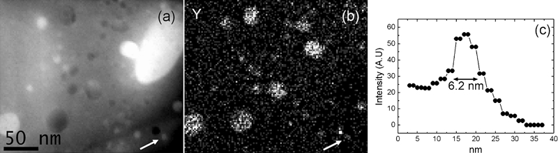
a HAADF-STEM image showing nanoparticles in ODS-Fe12Cr alloy, b corresponding Y Lα XEDS map and c intensity line profile across arrowed particle
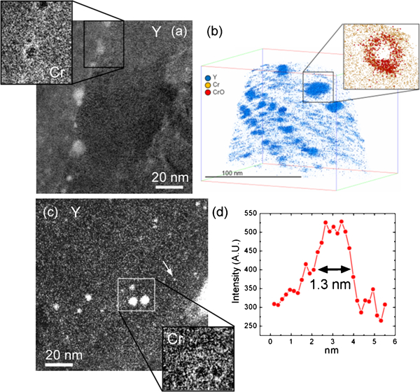
Images (EFTEM and APT) showing particles with core–shell structure in ODS-Fe12Cr and ODS-Fe14Cr alloys
The oxide particles dispersed in the steels appear to have evolved from the Y2O3 starting nanopowders. Some of the particles present a core–shell structure, having a Y–O rich core and a Cr rich shell.19 These core–shell particles were observed in both ODS-Fe12Cr and ODS-Fe14Cr steels. Figure 2 depicts how the Cr rich shell is observed by both EFTEM and 3D-APT. The shell had similar thickness in the two alloys, being ∼2 nm. Other particles seem to have incorporated Cr into their structure, showing a homogeneous Y–Cr–O composition, as observed for the ODS-Fe12Cr alloy. An example of the local analyses of one of these particles is presented in Fig. 3. These particles might correspond to ternary Y–Cr–O oxides.
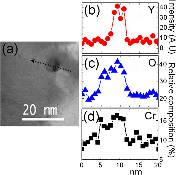
a HAADF-STEM image of two attached particles in ODS-Fe12Cr alloy, b Y Lα XEDS elemental profile and c O K and d Cr L2,3 EELS elemental profiles across line marked in a, revealing Y–Cr–O and Cr–O compositions
Although the nanoparticles have similar sizes in both alloys, their spatial distribution varied significantly from one another. The particles were much more uniformly distributed for the ODS-Fe14Cr alloy, as inferred from the estimation of the particle densities. In this alloy, the nanoparticle densities ranged between (0·10±0·02)×1023 and (1·5±0·3)×1023 m−3. In contrast, the particle densities found for the ODS-Fe12Cr alloy varied between (4·5±0·9)×1021 and (1·2±0·2)×1023 m−3. These densities were calculated in different areas from EFTEM images with average volumes of either 200×200×100 nm or 300×300×100 nm (thicknesses measured by EELS, as described in Ref. 20).
These changes in the particle distribution are probably a consequence of the differences in the processing routes of the two alloys since the milling conditions were quite different. The ODS-Fe12Cr steel was milled in an attrition mill for 27 h; meanwhile, the ODS-Fe14Cr steel was milled for 60 h using a planetary ball mill. 14 14,15 Moreover, the ODS-Fe14Cr steel was forged after the HIP process. All these changes could alter the final nanoparticle distribution.
Figure 4 reveals the presence of nanovoids with sizes as small as 2 nm for the ODS-Fe12Cr or 5 nm for the ODS-Fe14Cr alloys. 14 14,18 These nanovoids were only visible when imaged out of focus, appearing with bright contrast and surrounded by a dark Fresnel fringe in underfocused images, and with dark contrast and surrounded by a bright Fresnel fringe in overfocused images.21 They were frequently found next to the secondary phases, mainly the oxide nanoparticles. The voids were smaller than the ones found in the reference non-ODS alloys produced using the same powder metallurgy route but without the nanoparticle dispersion.18 This supports the role of the nanoparticle/matrix interface as an efficient sink for vacancies and gas atoms, and a preferential site for gas bubble formation, according to recent positron annihilation results obtained in ODS and non-ODS EUROFER steels.22 The formation of nanovoids appears to be a characteristic of steels processed by mechanical alloying and consolidated by HIP irrespective of the milling conditions and composition, at least if the milling process is carried out in Ar or He.14,18,23–25
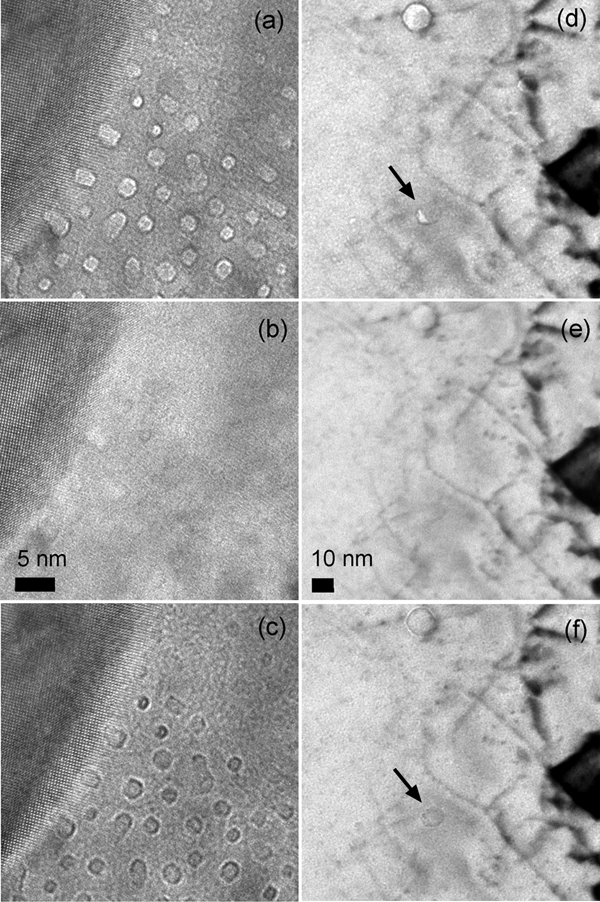
a–c through-focal series of small voids beside a carbide in the ODS-Fe12Cr alloy (a underfocused by 100 nm, b in-focus and c overfocused by 100 nm) and d–f through-focal series of nanovoids in the ODS-Fe14Cr alloy (d underfocused by 1 μm, e in-focus and f overfocused by 1 μm). The void arrowed is attached to an oxide nanoparticle
Some of these voids can contain entrapped gas atoms coming from the milling atmosphere. Void coarsening and gas bubble formation by gas diffusion towards the voids have been reported for ODS and non-ODS EUROFER steels subjected to isochronal annealing.22
The grain boundaries were analysed by APT, EFTEM and STEM-EELS. The results, as shown in Fig. 5 for the ODS-Fe12Cr alloy, reveal that some of the grain boundaries were enriched in C and/or Cr; meanwhile, other boundaries did not show any evidence of impurity segregation.26 The analyses obtained for the ODS-Fe14Cr alloy have also revealed Cr segregated at some grain boundaries, such as the one shown in Fig. 5c and d. The differences in the segregation behaviour of the boundaries could be due to a different local environment or grain boundary character.
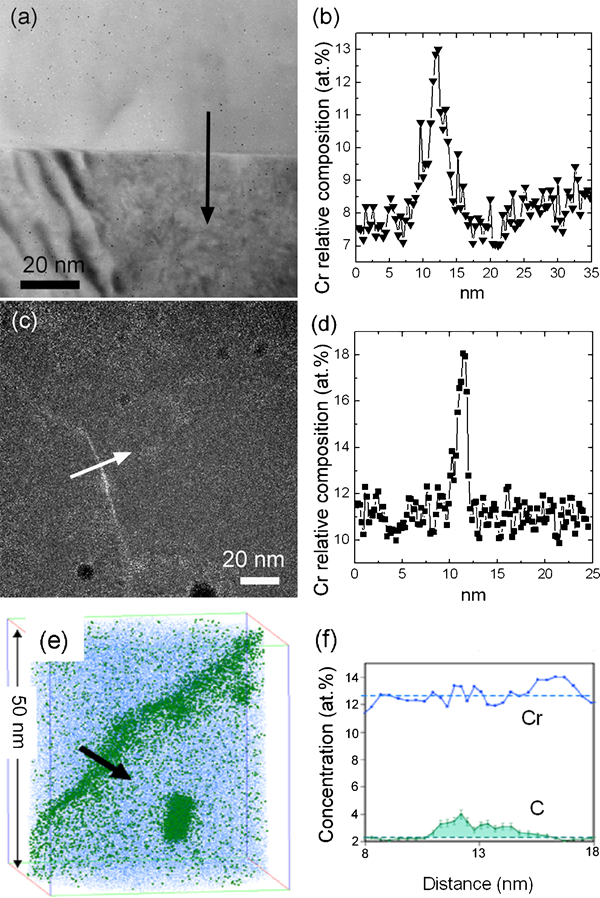
a HAADF-STEM image of a grain boundary in the ODS-Fe12Cr alloy and b EELS Cr L2,3 relative concentration line profile across the grain boundary. c EFTEM Cr M2,3 map of a region in the ODS-Fe14Cr alloy and d relative concentration line profile showing Cr enrichment across the grain boundary. e atom probe 3D reconstruction of the ODS-Fe12Cr alloy and f 1D concentration profiles obtained along cylinders placed at the positions indicated by the arrow
Conclusions
The present paper reviews how the combination of APT and high resolution TEM techniques, such as EFTEM or HAADF-STEM combined with XEDS-EELS, can provide near atomic level information indispensable for the characterisation of ODS steels. It was shown how APT and EFTEM allowed visualisation of small Y rich nanoparticles with core–shell structures where the Y signal was evident for particles as small as 1·3 nm. HAADF-STEM combined with XEDS and EELS was also used for particle characterisation, allowing the detection of other nanoparticles with a homogeneous Y–Cr–O chemical composition. The three techniques were also successfully applied for the investigation of the grain boundary chemistry. These results revealed Cr and/or C segregation to some of the grain boundaries. Furthermore, conventional TEM was applied to check the presence of nanovoids with sizes of <5 nm that were frequently found nearby or attached to the secondary phases present in the alloys.
Footnotes
Acknowledgements
The present research has been supported by the FP6 Euratom Research and Training Programme on Nuclear Energy, the Fusion Energy Materials Science (FEMaS) FP7 coordination action, the IP3 FP6 ESTEEM project under contract no. 026019 and the Consejería de Educación de la Comunidad de Madrid, through the program ESTRUMAT-CM S2009MAT-1585. EAM thanks the Royal Society for the financial support (RS Dorothy Hodgkin fellowship).