
Abstract
The magnetic pulse welding of Al-A1050 to Mg alloys was successfully performed, and the structural–mechanical properties of the interfacial bonding layer produced between dissimilar metals were studied. The morphology of the interface layer has a typical wavy pattern with an average thickness of 20 μm. Compositional microanalysis showed that the composition of the interfacial layer is Al–50 at-Mg and is practically uniform, being a direct outcome of the local melting effect, intensive mixing of the melt and a rapid rate of solidification. The composition of the bonding layer corresponds to the Al supersaturated intermetallic β phase (Mg17Al12). The elastic modulus (and the hardness) of the interfacial layer was measured using the nanoindentation technique, and its value of 60·2±1·4 GPa is in good agreement with the value calculated from first principles in the literature (57·3 GPa) for the Mg17Al12 intermetallic phase.
Introduction
Vehicle weight reduction is one of the major means available to improve automotive fuel efficiency. High strength steels, aluminium and polymers are already being used to significantly reduce weight, but substantial additional reductions could be achieved by greater use of low density magnesium and its alloys. Nevertheless, further efforts in the development of high quality dissimilar joints between magnesium and aluminium alloys are essential. The Al–Mg binary phase diagram shows that direct attempts to fusion weld Al to Mg alloys may create significant quantities of melting related, cracking susceptible intermetallic phases (IMPs): Al3Mg2 and Al12Mg17.1 A possible approach to control intermetallic compound formation and keep their total volume as small as possible is to use a lap joint configuration2 utilising a fast joining technology. Since the characteristics of the interfacial layer formed during the welding process influence the macroscopic behaviour of the joint, knowledge of its structural–mechanical properties is essential.3 However, the thinness of the intermetallic layer makes conventional mechanical property evaluation methods unsuitable for the precise determination of interface properties.3
Of the many solid state welding processes, magnetic pulse welding (MPW) has proved to be a very attractive technology.3–5 The technology has gained the attention of the welding community because it enables joining similar and dissimilar materials in microseconds; the simple non-contact process is fast and clean, and creates no heat affected zone (HAZ).6–28 Material conductivity, ductility and strength are important criteria, and MPW works best when using conductive alloys such as copper and aluminium. A great deal of experimentation has been and is being carried out using the MPW process in order to weld aluminium parts to steel, aluminium to copper, copper to steel and stainless steel to steel (for example, see MPW welded aluminium to steel parts in Fig. 1). The main drawbacks are that the outer part has to be plastically deformable (ductile), and the inner part must have sufficient structural strength to withstand the impact. Therefore, it is not possible to MP weld thin walled tubes unless there is a mandrel backing up the inner part.
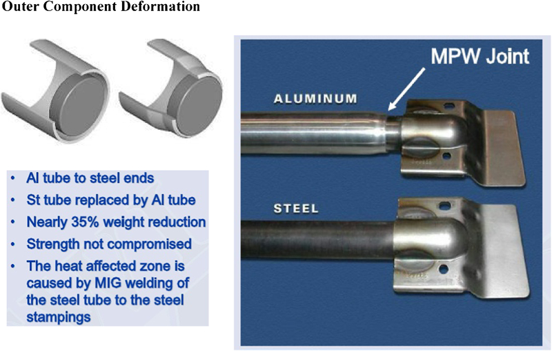
Typical MPW joint: Al–St crash beam for car door4
In MPW, a high intensity current (up to 1·5 MA) discharged through a coil initiates an eddy current in the conductive outer workpiece.4 The repulsion between the two magnetic fields creates a high pressure (in the GPa range) on the outer component, which accelerates it across the standoff gap, resulting in an angular collision (usually 5–20°) at a high collision velocity of 200–400 m s−1 with the inner workpiece.29 The magnitude of the magnetic pulse and the standoff gap size determine the velocity of impact between the components, and the axial non-uniform magnetic field provides the suitable impact angle. The resultant oblique impact creates very high localised pressures (several times the yield strength of the alloys) at the collision point.30 These pressure waves travel away from the collision point at the acoustic velocity of the metals. Since the collision is moving forward at a subsonic rate, intensive plastic deformation is created at the immediately approaching adjacent surfaces. The local pressures are sufficient to spall a thin layer of the strongly heated and deformed metal from each surface and eject it away in a cumulative jet. Although there is much heat generated at the interface, there is no time for heat transfer to the components, leading to extremely rapid rates of cooling (105 K s−1) in the bonding zone.
The surface contaminants, oxides and impurities are stripped away in the jet, leaving two atomically clean surfaces. Hence, it is not the original surfaces that are joined together, but the fresh, unaffected material below the original surface layers. The newly created clean metal surfaces impact at high pressures, forming a joint which typically does not exceed 1 cm in length (Fig. 2). Under these circumstances, while mechanical mixing and intensive plastic deformation take place, manifestations of local heating are observed as enhanced solid state diffusion, inducing solid state bonding, or as local melting, creating an interfacial bonding layer. As a result of these processes, supersaturated solid solutions30 and/or stable or metastable IMPs31 are expected to be formed in the bonding zone of MPW joints.
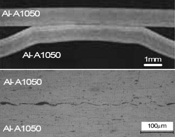
Wavy interface in MPW joint of Al-A1050 to Al-A105027
Since the nature of the interface determines the quality of the MPW joints, this contribution intends to shed some light on the structural–mechanical properties of the bonding zone between Al and Mg alloys using the nanoindentation techniques.32 This method has become widely used in the last decade in the field of structural–mechanical characterisation of small volume welded joints, 33 33,34 coatings, surfaces and composites.35–37 Despite the significance of those properties, they are not measurable by any conventional method. Nanoindentation allows confining the mechanical testing to dimensions of only a few micrometres or less, allowing the accurate mechanical testing of the thin bonding interfacial layers created by the MPW process. 38 38,39
Experimental
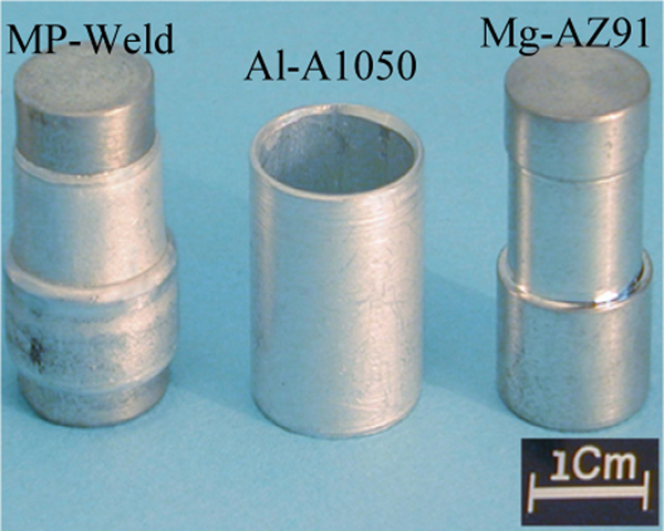
Joints of dissimilar materials with close physical properties, e.g. Al-A1050 to the Mg-AZ91 alloy and to the Mg-AM50 alloy, were prepared by the MPW technique. In all the experiments, the Al-A1050 flyer component was in the form of a pipe and the stationary component, a bar placed inside the pipe (Fig. 3). MPW parameters and experimental set-up are described elsewhere.22 After welding, the specimens were cross-sectioned and prepared for examination by standard metallographic procedures and examined using light optical microscopy and scanning electron microscopy. Microanalysis by energy and wavelength dispersive spectroscopy (EDS and WDS) was used to evaluate the local distribution of alloying elements in the joint vicinity. Measurements of hardness and modulus were made by instrumented nanoindentation (Nano Indenter XP; MTS Systems, Oak Ridge, TN, USA) using a Berkovich indenting tip (Micro Star Technologies, Huntsville, TX, USA). The indentations were performed using the ‘continuous stiffness method’ (CSM), whereby a small (2 nm or less) modulation is applied to the indenting tip, and the instantaneous modulus and hardness values are calculated continuously using the known tip area function. The nanoindentation measurements were performed across the bonding zone at regular spacing. The basic equations developed by Oliver and Pharr were used for the calculation of indentation modulus E and hardness H.40 Nanoindentation differs from bulk testing and even microhardness measurements in several aspects. First, the measurement is local and can be influenced by defects, such as voids, inclusions and crystalline defects. Whereas these allow insights into the microscopic behaviour, sufficient statistics are required to obtain a meaningful value. Second, the indentation depths are small; the surface state (roughness, presence of oxide and internal stresses) can influence the results. The application of the CSM method is thus critical so that the development of hardness and modulus with depth at a single sample position can be used to ascertain when the surface effects have been overcome. It can also be noted that the CSM measurement provides essentially tens of E and H values at each indent position, as opposed to standard quasi-static indentation, which provides only one value. Finally, in comparing micro- and nanohardness, the latter represents area at maximum load, whereas the former is for relaxed load. The microhardness of the joint was also measured by conducting Vickers tests; the conversion of the Vickers values (kg mm−2) to hardness in gigapascals was carried out according to ISO 14577-1 (2002), Annex F.41
Al-A1050 to Mg-AZ91 MP weld
Results and discussion
Characterisation
Macro- and microstructure
The macrostructure of a welded Al-A1050 to Mg-AZ91 specimen is presented in Fig. 4. No HAZ is observed in the vicinity of the interface. At higher magnifications, the formation of an interfacial bonding layer is observed, as well as the typical wavy morphology of the weld zone (Fig. 5). The same characteristics were found in the case of the MP Al-A1050 to Mg-AM50 welds (Fig. 6), but in discrete regions, thick interfacial layers were created (∼80 μm). Again, no HAZ has been observed adjacent to the bonding layer; however, cracks perpendicular to and terminating at the interface have been observed in the thick regions of the interfacial layer.
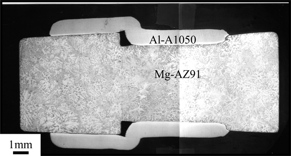
Macrostructure of cross-sectioned MP welded Al-A1050 to Mg-AZ91 specimen: outer Al-A1050 tubes and inner Mg-AZ91 rod gross deformations are evident
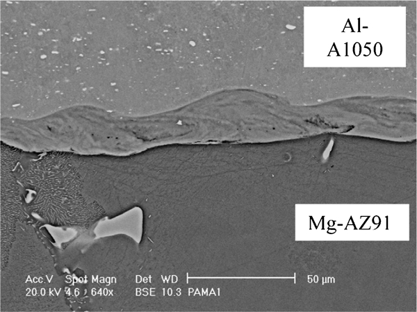
Micrograph (BSE) of MP Al-1050/Mg-AZ91 weld: wavy morphology of interfacial layer is observed; no HAZ is observed near interface, and original microstructure of Al 1050 (top) and Mg-AZ91 (bottom) is maintained
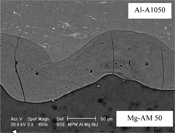
Micrograph (BSE) of MP Al-A1050 to Mg-AM50 weld: local thickness of bonding layer is ∼80 μm, and it contains cracks perpendicular to interface
Chemical composition of interfacial layer
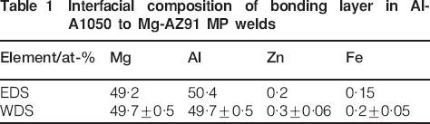
The interfacial layer microcomposition was measured, and its uniformity was confirmed by quantitative WDS line scans across the interface. See, for example (Fig. 7), the reasonably uniform distribution of zinc (present only in the Mg rod) and iron (present only in the Al tube as Al3Fe particles) across a 15 μm interfacial layer in an Al-A1050 to Mg-AZ91 MP weld; the composition of the bonding layer determined by WDS and EDS analysis, for the same MP weld, is summarised in Table 1. The uniform composition of the interfacial layer appears to be an inevitable outcome of the local melting effect, intermixing in the melt pool, as well as a rapid rate of solidification.22
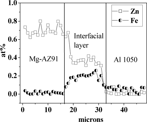
Practically uniform distribution of Zn and Fe across interfacial layer in Al-A1050/Mg-AZ91 MP weld: zinc is present only in Mg rod as alloying element, whereas iron is present only in Al tube as Al3Fe particles/inclusions
Interfacial composition of bonding layer in Al-A1050 to Mg-AZ91 MP welds
The XRD22 and microanalysis results confirm that the phase formed at the interface is the β IMP. According to the Al–Mg binary phase diagram, the β phase composition range increases with temperature. While at ambient temperatures, the Mg/Al ratio is 1·4, at 450°C, the ratio varies approximately between 0·82 and 1·4. Therefore, it can be concluded that the β phase formed at the MPW interface is an Al supersaturated intermetallic β phase.
At this point, once the composition and the structure of the interfacial layer have been determined, the perpendicular cracks reported above can be explained as follows. It seems reasonable to assume that the layer is under internal tensile stresses, and the crack formation should depend on the thickness of the interfacial layer. Three possible factors may initiate internal stresses in the interfacial layer, resulting in cracking: one factor is the effect of a difference in the densities of the bonding layer compared to a mixture of the Al and Mg phases (resulting in differential volume changes), the second is the difference in the coefficients of thermal expansion (CTE) and the third is the tensile longitudinal stresses produced during the radial deformation of the components under the magnetic pressure. A simple calculation shows that at room temperature, the density of a mechanical Al–50Mg mixture is 2215 kg m−3. Assuming that the β phase is a substitutional solid solution and the lattice parameter remains constant, then for the same temperature, the theoretical density of an Al supersaturated β phase (Al–50 at-Mg) is 2107 kg m−3 (for comparison, the theoretical density of the β phase Mg17Al12 is 2088 kg m−3). The lower density of the interfacial layer compared to that of the Al–50Mg mixture should result in compressive stresses but would not cause cracking. If the CTE of Mg17Al12 is considered to be as low as that of Mg2Si42 (7·5×10−6 K−1)43 compared to Mg or Al (29 and 27×10−6 K−1 respectively), then the significant difference in CTE should result in compressive stresses during the cooling stage of the joint. Under these circumstances, it may be safely assumed that the longitudinal tensile stresses created in the Al tube wall and in the Mg rod, and associated with the component radial reduction, play a major role in the interfacial bonding layer cracking.
Mechanical properties
An example of nanoindentation measurements across an Al-A1050 MP weld interface is shown in Fig. 8. The microhardness of the interfacial layers was also determined by the complementary Vickers test method; the conversion of the Vickers values (kg mm−2) to hardness values (GPa) was carried out according to Ref. 41. Table 2 presents the hardness values determined by the two complementary test methods, namely, depth sensing indentation and Vickers technique and the elastic modulus. The elastic modulus of Al and Mg obtained in the present study is similar to the values measured by Venkateswaran et al.,33 Urena et al.37 and Chen et al.44 However, the elastic modulus of the MPW interfacial layer consisting of the β phase was not reported in the literature; the elastic modulus of the β phase was calculated from the first principles by Wang et al.,45 and its value was reported to be 57·3 GPa, which is very close to the authors’ measured value. The Vickers microhardness values measured on the welded Al-A1050 and Mg-AZ91 components are slightly lower than those measured by the nanoindentation technique, yet in the case of the β phase, the values are reasonably close. The divergence between the hardness values obtained by the nanoindentation technique compared to the microhardness values can be attributed to local strain hardening as a function of distance from the interface/weld; the nanoindentation measurements were performed adjacent to the interfacial layer boundary (up to 40 μm), whereas the microhardness test was carried out at a distance of 100–250 μm from the interfacial layer.
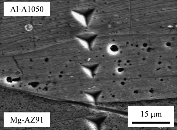
Nanoindentation line scan across Al-A1050/Mg-AZ91 MP weld interface (SEM image): in calculation procedure of elastic modulus and hardness (Table 2), indentations which are located at interface were not taken into account
Young's modulus and hardness obtained by nanoindentation method compared to results obtained by Vickers technique*
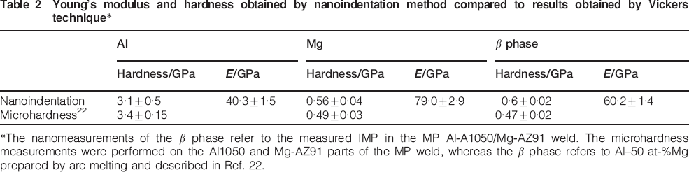
*The nanomeasurements of the β phase refer to the measured IMP in the MP Al-A1050/Mg-AZ91 weld. The microhardness measurements were performed on the Al1050 and Mg-AZ91 parts of the MP weld, whereas the β phase refers to Al–50 at-Mg prepared by arc melting and described in Ref. 22.
Summary and conclusions
The unique MPW technology offers new opportunities for dissimilar material joining components which cannot be welded by conventional welding methods. In the present study, Al-A1050 to Mg alloys were MP welded, and a wavy interfacial bonding layer (∼20 μm) was formed. The EDS and WDS compositional analyses showed that the phase formed at the interface is an Al supersaturated β phase (Al–50 at-Mg), and the alloying elements are distributed uniformly across the bonding layer. The elastic modulus of the β phase (Al–50 at-Mg) was measured by the nanoindentation technique and reported here for the first time. The calculated elastic modulus value, from the first principles45 (57·3 GPa), is reasonably close to the direct measured values by the nanoindentation technique (60·2±1·4 GPa).
Footnotes
Acknowledgements
The authors wish to express their thanks to Y. Livshitz and V. Shribman from Pulsar Ltd (Yavne, Israel) for performing the MP welds, to Dr U. Admon and Dr S. R. Cohen for many fruitful discussions, to Mr C. Cotler for the preparation of the metallographic samples and to O. Kaplan for his technical assistance.