
Abstract
The microstructure evolution of ultrafine grained C–Mn steel during tensile deformation was investigated using scanning electron microscopy. The surface morphologies and orientation imaging micrographs at different locations near the fractures were discussed. No obvious evident work hardening was identified and partially attributed to the strain driven grain boundary motion of grain rotation and/or grain boundary sliding, especially at the initial stage, while the dislocation activities gradually participate in as deformation proceeds.
Introduction
Ultrafine grained steels have been extensively studied in recent years because of their great potential applications. Although the strength of steels can be doubled by means of refining the grain size,1–3 there is always a sudden drop in uniform elongation with a grain size of ∼1 μm, which is accompanied by a high yield ratio of ∼1 when the samples are loaded with uniaxial tension.4–10 This relatively lower work hardening rate has become a bottleneck that causes limited use of the steels. Most of those flatter stress–strain curves show unstable plasticity with small total elongation and/or uniform one; however, there are still some cases whereby much larger elongation (>15) can also be obtained in ultrafine grained steels 1 3 6 1,3,6,10 even at ambient temperature.
It is reported in some research works about ultrafine grained pure Al and other alloys that favourable plasticity can also be realised, and it is always ascribed to the motions of grain boundaries more or less, especially at relatively higher temperatures and/or at lower strain rate. 4 4,11 However, the motion of grain boundaries, such as grain boundary sliding and rotation of grains, is often reported in nanocrystalline materials, and it is seldom considered in ultrafine grained steels, let alone in the tensile process of it.
The present study deals with the behaviours of microstructure evolution of ultrafine grained plain C–Mn steel when it is exerted with uniaxial tension at room temperature. The effect of grain boundary motion on the work hardening rate is also investigated in the present work.
Experimental
A plain C–Mn steel with a chemical composition of 0·14C–0·24Si–1·38Mn (mass-) was used in the present study. The initial microstructure of ferrite/spheroidised pearlite combined with cementite was prepared by rolling ferrite/pearlite at 600°C followed by isothermal holding for 1 h at the same temperature. Test specimens with dimensions of 60 mm (length)×15 mm (width)×12 mm (thickness) were cut from the steel plate made from this material.
The specimens were first cold rolled 50 with Φ300 milling roll, followed by a rapid heating performed at a heating rate of 10–15°C s−1 in a high temperature resistance furnace. After being held for 1–5 s at a certain temperature in the range of 800–900°C, the specimens were air cooled to 650–750°C and then immediately rolled by single pass rolling with a reduction of 60–70. Finally, the deformed samples were air cooled to room temperature. Two samples were prepared through this route of process, labelled as samples A and B respectively, the microstructures of which are illustrated in Fig 1. Tensile samples were machined according to the national standard (GB/T 228-2002, eqv ISO 6892:1998). All tensile tests were carried out in a SANS CMT5105 (100 kN) tensile machine at ambient temperature, and the gauge area of specimens was 25×10 mm. The microstructures were observed by scanning electron microscopy (SEM, FEI Quanta 600). In order to clarify the microstructure evolution of the samples during the tensile process, two sampling positions were adopted, one of which is nearly close to the fracture, and the other is away from it. Electron backscattering diffraction was employed to perform orientation imaging microscopy (OIM). The step size adopted was 0·3 μm.
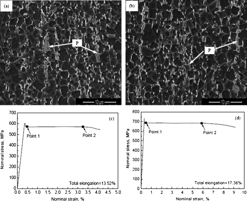
Morphologies (SEM) of samples A and B corresponding to their nominal strain–stress curves
Results and discussion
As shown in Fig. 1a and b, a combined microstructure of ferrite+pearlite+cementite was obtained in both samples A and B, and the grain size of ferrite in both samples is similarly 2±0·5 μm. The grain boundaries demonstrate that most of them are high angle ones.
The nominal stress–nominal strain curves are summarised in Fig. 1c and d. Both of them show no work hardening after the yield drop, which is similar to type II according to the study of Yu et al.12 By careful analysis, however, it is observed that there is still a little difference between type II curve and those in the present study. For type II, the stress starts to decrease during the propagation of Lüders band, while in the present study, there is a steady flow stress level from the lower yield point in Fig. 1, and the corresponding stresses for samples A and B are 570 and 683 MPa respectively. Furthermore, a gradual decrease in flow stress appears after a certain elongation in a range of 2–5, although the stress level almost remains unchanged, as shown from point 1 to 2 in Fig. 1. This tensile behaviour is much more similar to that of the ultrafine grained aluminium (d = 0·35 μm) at 77 K.12 However, the fracture surface was not flat, and also there was no remarkable shear angle from the tensile axis. Figure 2 shows the macrograph of sample B after fracture. Lüders band was more or less found near the fracture, but no serrated flow that characterises the propagation of plastic strain within a Lüders band 13 13,14 could be identified. Then, the grain boundary motion that the authors have proposed was probably an accompanying deformation mechanism during the uniform deformation.
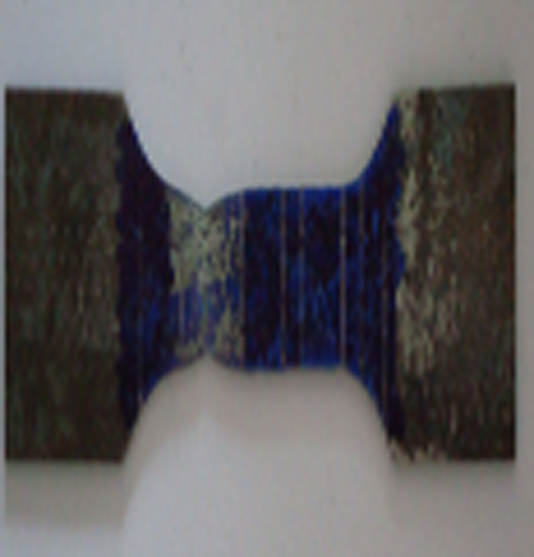
Macrograph of sample B after fracture
Figure 3 illustrates SEM images at different locations on sample B after tensile failure. In Fig. 3a, a lot of ferrite grains were found to be coarse up to ∼5 μm, as indicated by dotted circle, and the grains are one time larger than those in the predeformation microstructure (Fig. 1b). The distribution of grain size at this position is much more asymmetrical in comparison with that in Fig. 1b. It is evident that grain growth happens in the initial stage of tensile deformation rather than work hardening, as equiaxed grains are still preserved at this condition. Although this phenomenon is mostly found in nanocrystalline materials15–17 and/or in the high temperature deforming process of ultrafine materials, 5 5,18 it could also be attributed to the motion of grain boundaries, such as grain boundary sliding and grain rotation, which enables the change from high angle (15–180°) grain boundaries to low angle ones (<15°) between adjacent grains, and these grains finally merge into one coarser grain.
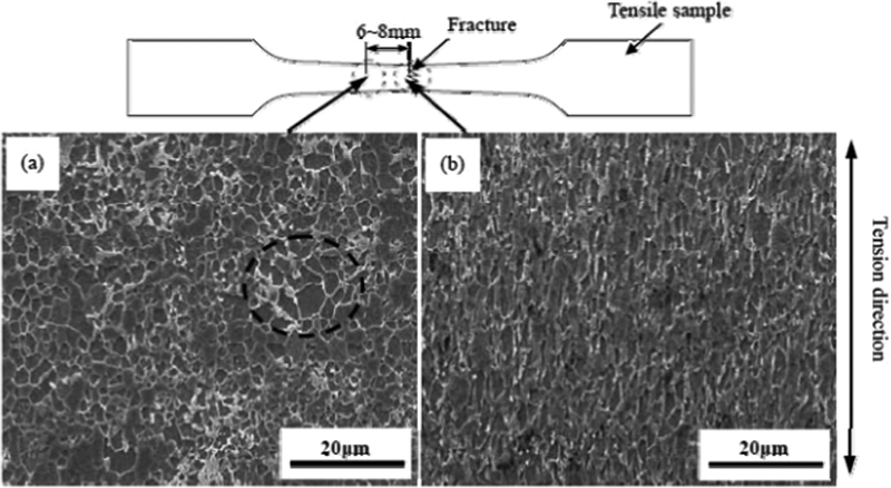
Morphologies (SEM) at different locations of sample B near tensile fracture
Figure 1b shows a microstructure at the fracture where deformed grains can be easily identified. Generally, it is considered as a certification of dislocation activities. However, it cannot simply be perorated that only dislocation plays a role in tensile deformation now, since there is no significant work hardening in this sample's stress–strain curve (Fig. 1d). Generally, a lack of strain hardening capability of ultrafine grained materials is recognised as a dynamic balance between dislocation generation during deformation and annihilation in the recovery process.19 However, it is difficult to explain the grain growth at the initial stage using this theory. A detailed information about microstructure evolution in the tensile deformation of sample B can be intuitively demonstrated by the OIM microstructures at and near the fracture obtained by electron backscatter diffraction (EBSD) measurement, as indicated in Fig. 4. According to Fig. 4a and c, lots of equiaxial coarser grains in the size of 5±0·5 μm are obtained, and the number fraction of high angle grain boundaries at this location is ∼74. In addition, some larger grains are obviously divided into several small equiaxial ones by low angle grain boundaries in Fig. 4b. That definitely presents direct evidences of strain induced grain boundary motion.
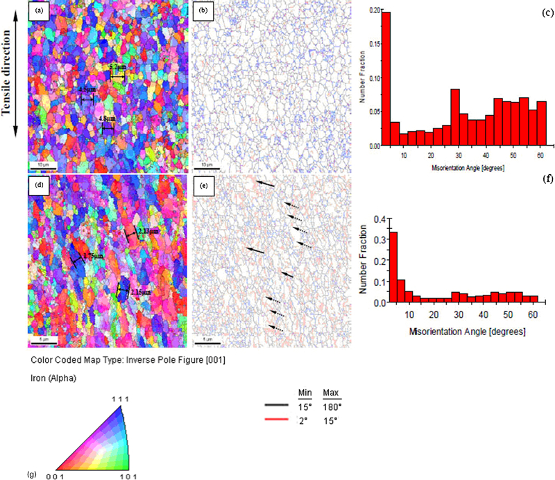
Orientation image obtained by EBSD measurement and quantitative distribution of misorientation angles at different locations near tensile fracture of sample B
Additionally, some typical deformed grains along the tensile direction are evolved at the fracture, which can be evidently found in Fig. 4d and e. In Fig. 4d, the dimensions of deformed grains perpendicular to the tensile direction are measured to be ∼2 μm, and those parallel to the tensile direction differ widely from one to another. Those grains indicated with dotted line arrows in Fig. 4e are mostly separated into several equiaxial grains by low angle grain boundaries, although some low angle grain boundaries are probably dislocations, as pointed out with solid line arrows. Comparing the number fraction of misorientation angle between Fig. 4c and f, the number fraction of low angle misorientations increases significantly to 51·9, and most of the increment depended on low angles of around 2–5°. Therefore, although the tensile deformation is coordinated by dislocations at the later period, distinct work hardening still cannot be activated while grain boundary motions always exist during the uniaxial tension.
Basing on the morphology of tensile fracture in Fig. 5, a typical ductile fracture can be recognised as equiaxial dimples are present. Identical to the dimensions of the grains measured in Fig. 4d, the size of dimples varies at ∼2 μm, suggesting that tensile failure happens right at this moment.
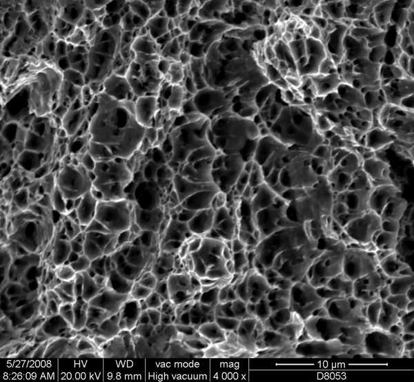
Tensile fracture morphology of sample B
Conclusions
During the tensile deformation of ultrafine grained C–Mn steel, no significant work hardening and serrated flow were found in the nominal stress–nominal strain curves. According to the analysis of microstructures and OIM at different locations near the fracture, strain induced grain boundary motion, such as grain boundary sliding and grain rotation, was identified. This grain boundary motion caused a certain growth of the ultrafine ferrite grains at the initial stage of tensile deformation with an elongation ⩽2–5. Grain boundary motion was an accompanying deformation mechanism during the uniform deformation, whereas the deformation was mainly coordinated by dislocations, especially after necking happened. However, more quantitative measurements are required to be made of the different grain size conditions.
Footnotes
Acknowledgements
The authors are grateful to Dr H. T. Liu and Dr Y. H. Guo for their help and advices. Gratitude is also extended to Dr Z. C. Zhang and Dr H. Q. Han for their indispensable assistance. The present work was financially supported by the Project of National Natural Science Foundation of China (project no. 50524702).