
Abstract
A ceramic coating was formed on the titanium alloy by microarc oxidation in an electrolyte containing nano-Fe2O3, emulsifier OP-10 and sodium phosphate. The composition, surface and cross-sectional morphology and the element compositions of the coatings were characterised by X-ray diffraction, scanning electron microscopy and energy dispersive X-ray analysis system. The spectral emissivity of the coatings was measured by a Fourier transform spectrometer apparatus. The bonding strength between the coating and the titanium alloy was studied by tensile strength test. The thermal shock resistance of the coatings was also evaluated. The results showed that nano-Fe2O3 was incorporated into the coating, and the coating had high emission at the wavelength range of 3–20 μm. The bonding strength was 33·2 MPa, and after being subjected to severe thermal shocking for 50 cycles, little peeling-off of the coating occurred.
Introduction
High friction heat from acute friction between aircraft surface and atmosphere causes a severe increase in surface temperature during hypervelocity flights and affects the precision guidance. To improve the precision guidance, metal thermal protection systems (MTPS) was widely used in the form of rigid surfaces in areas of moderate working temperature.1–4 Furthermore, elevated temperature and high heat fluxes demand that the MTPS materials must be endowed with good oxidation, thermal shock resistance, dimensional stability and ablation resistance. Because of the low thermal conductivity and the high oxidation resistance, Fe2O3 and TiO2 are used as insulator layers, which can make oxidation increased resistance of MTPS.5–7
The development and application of modern protective coating and technology are focused on improving the durability and main service properties of the coating and ensuring reliable properties, cutting the cost and time of the prepared processing. The existing traditional thermal protective coating on the metal surface contains an oxidation resistance coating bond with metal and a high emissivity ceramic outer layer. The prepared process is multistage, with the combination of such processes as diffusion plasma spraying, galvanic coating and electron beam deposition.8–10 It takes much time and money to complete it.
Microarc oxidation (MAO) is gaining increased attention as a novel and unique technique for depositing thick, dense and ultrahard ceramic coatings on Al, Mg, Ti and their alloys.11–13 The MAO process, also called plasma electrolytic oxidation, is a complex process combining concurrent partial processes of oxide film formation and dissolution. It is a room temperature electrochemical process and suitable for the formation of uniform coatings on substrates with complex geometries. The coatings synthesised through the MAO process have exhibited excellent mechanical properties and super adhesive strength between the substrates. The excellent wear, friction, corrosion, electrical and thermal properties of these coatings are of particular interest to textile machine components, aerospace components and engineering equipment components.14 However, a high emissivity ceramic coating prepared by MAO technology used as thermal barrier coating has not been reported.
In the present paper, a ceramic coating prepared by MAO in sodium phosphate electrolytic contains nano-Fe2O3. Nano-Fe2O3 was incorporated into the coating, and the emission of the coating was studied.
Experimental
Ti6Al4V discs with a diameter of 30 mm and a thickness of 6 mm were used as the substrate. The surface of the discs was polished with a waterproof abrasive paper up to 1200 grits, making the roughness of the surface Ra = 0·2 μm, and then ultrasonically cleaned in distilled water followed by acetone. The MAO process was conducted on a homemade 20 kW MAO equipment. The discs were used as anode, and a stainless steel container served as cathode. The container with a sample holder as the electrolyte cell was also used as a stirring and cooling system. During the MAO treatment, a constant voltage mode was applied. The anodic voltage was kept constant at 450 V, the cathodic voltage was controlled at 0 V and the frequency was kept at 100 Hz. The duration of the MAO treatment was 20 min. The electrolytic solutions were composed of 6 g L−1 Na3PO4 in distilled water without or with 3·0 g L−1 nano-Fe2O3 and 20 mL L−1 emulsifier OP-10 addition. The ceramic coating was prepared in electrolytes without or with nano-Fe2O3, which are noted as MAO1 and MAO2 respectively.
The phase composition of the coatings was examined with a RICOH D/max-rB automatic X-ray diffractometer (XRD) using a Cu Kα source. The surface morphologies of the produced coatings were studied by scanning electron microscopy (SEM, S-4800, Hitachi Co., Japan). The element distribution on the surface of the coating was investigated by energy dispersive spectroscopy (EDS, Oxford Model 7537, UK). The coating thickness was measured using an eddy current based thickness gauge (CTG-10, Time Company, China). The average thickness of each sample was obtained from 10 measurements at different positions. The roughness of the coating was measured by a current based roughness gauge (TR-200, Time Company, China). The average roughness of each sample was obtained from eight measurements at different positions. The bonding strength between the coating and the substrate was investigated by the direct pull-off method (modified ASTM C-633). During the thermal shock tests, the samples were heated up to 700°C and held for 2 min to make the body temperature uniform. Then, the samples were quickly taken out and put in the air for 5 min. The tests were repeated for 50 cycles. The authors carefully observed the coating surface and identified whether visual cracks or large area flakes are produced. The emissions of the coatings were measured by a Fourier transform infrared spectrometer with a simple Michelson interferometer that consists of a corner cube mirror and a KBr beam splitter. The spectral range between 0·6 and 25 μm is covered by a photovoltaic HgCdTe and a silicon photodiode detector. The sample was heated by passing a controlling current through the heater, and the temperature of the specimens was kept at 700°C. Both the thermocouple and the pyrometer were employed for monitoring the temperature of the heater and the sample. Two reference blackbodies were used to calibrate and compensate the linearity and shift of the system. More details about the equipment can be found elsewhere.15 The vertical direction emission of the sample was tested.
Results and discussion
Surface and cross-section morphologies
Surface and cross-section SEM photos of the MAO2 coating are presented in Fig. 1b and c. The elemental composition on the surface of the MAO2 ceramic coating was analysed by EDS, and the results are shown in Fig. 1d. Figure 1a shows the surface morphology of the MAO1 ceramic coating. It can be clearly seen from Fig. 1a that many micropores exist on the surface of the coating, which is the typical feature of MAO coatings. The size of pores formed after the sparks decayed is rather small and uniform. At higher magnification of the MAO1 coating, the authors can see that the diameter of the pores is <4 μm. Microarc oxidation is based on the conventional anodic oxidation of metals and alloys in aqueous electrolyte solutions. However, it differs from the conventional anodic oxidation by the discharge feature, which is produced when the applied voltage exceeds the critical breakdown voltage of the insulated film. The discharge leads to a localised high temperature and high pressure in the corresponding discharge channel, and when the melted produced mass erupts from the discharge channel, the pores remained. The formed products are rapidly cooled by the adjacent electrolyte and solidify to deposit on the surface.
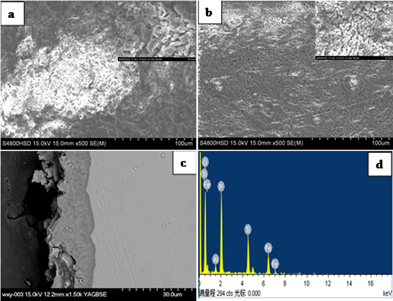
a, b surface morphology, c cross-sectional microstructure and d EDS pattern of coatings
In Fig. 1b, no micropores can be seen, with small grains distributed over the surface of MAO2. At higher magnification of the coating, it can be seen that the discharge channels are sealed by small grains, and the surface of the MAO2 coating looks like a pan. In microarc processing, the nano-Fe2O3 moves to the surface of titanium in electric field force, attaches to the surface and joins the discharge channel. In the discharge channel, the temperature is higher than 104 K,16 and the nano-Fe2O3 is sintered.
The roughness of the MAO2 coating is 0·52 μm. It is relatively smoother than that of the MAO1 coating, of which the surface roughness is 0·97 μm. This is in accordance with the surface in the SEM photos.
Figure 1c shows the cross-sectional morphology of the MAO2 coating formed on Na3PO4 electrolytic with nano-Fe2O3 addition. The coating with thickness of ∼18 μm is dense, and the thickness of MAO1 measured by an eddy current based thickness gauge is ∼15 μm. The interface between the substrate and the coating is smooth. It should be noted that there are no fracture sites in the interface between the coating and the substrate, indicating that the adhesion between the coating and the substrate will be good. Figure 1d shows the elemental composition on the surface of the MAO2 coating. Clearly, the elements of O, Al, P, Ti and Fe are involved in the coating. The elements Ti and Al from the substrate and the elements Fe and P from the solutions are incorporated into the coatings.
Phase composition of coatings
The XRD patterns for the MAO coatings formed on Ti6Al4V in Na3PO4 electrolytic solutions without and with nano-Fe2O3 are shown in Fig. 2. The XRD patterns indicate that rutile and anatase TiO2 are the main oxides existing on the oxide coating, regardless of the electrolyte composition. The characteristic diffraction peaks corresponding to the titanium substrate also appeared in the patterns. However, when Ti6Al4V is oxidised in the electrolyte containing nano-Fe2O3, the peaks of Fe2O3 are well defined in the XRD patterns. The diffraction peaks of rutile TiO2 become stronger with nano-Fe2O3 addition, while the diffraction peaks of anatase TiO2 become weaker, which maybe exit anatase TiO2 transforming to rutile TiO2. The pattern strength of the substrate become weaker with nano-Fe2O3 addition, which maybe because the coating became more compact and thicker.
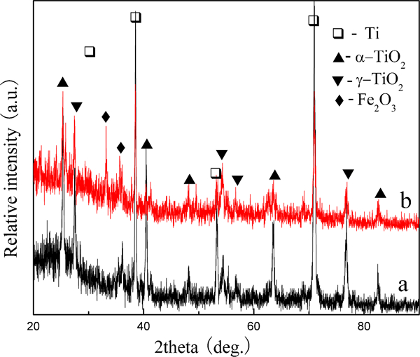
X-ray diffraction patterns of coatings prepared in electrolytes a without or b with nano-Fe2O3
Thermal shock resistance tests
Figure 3a and b shows the surface morphology of the MAO1 and MAO2 ceramic coatings after 50 times of air cooling thermal shock tests. It is obvious that there are some peeling-off in the MAO1 coating after being subjected to severe thermal shocking. The part of the peeling off is very clear, and in some sections, almost all of the outer layers are peeled off. Some peeling-off also occurred in the MAO2 coating, but it could not be observed by the eyes. From Fig. 3b, it could be seen that many particles distributed in the coating surface, just like before the thermal shock test, and the peeling happened on the surface of the outer layer, which indicates that the coating possesses a good thermal shock resistance. The thermal shock resistance of the MAO2 ceramic coating is better than that of the MAO1 coating.
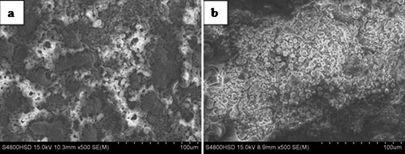
Surface morphologies after thermal shock test
Bonding strength
The bonding strength before and after the thermal shock test was studied by the pull-off tensile tests. The results are shown in Fig. 4. It was found that before the thermal shock test, the bonding strength was higher than 32 MPa. After the thermal shock test, the bonding strength of the MAO1 ceramic coating decreased a lot, but the bonding strength of the MAO2 ceramic coating decreased a little, which may be because of the growth stress at high temperature. However, all the coatings after the thermal shock test showed a tensile strength higher than 27 MPa, and the bonding strength was much higher than that of plasma spraying on Ti6Al4V.17
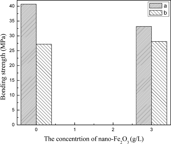
Bonding strength of coatings prepared a before and b after thermal shock test
Emissivity characterisation
Infrared radiation with wavelength in the range of 3–20 μm is important in heating and cooling. The Fourier transform infrared spectral emissivity values of the substrate and the MAO1 and MAO2 ceramic coatings with a wavelength range of 3–20 μm are shown in Fig. 5. The substrate has the lowest spectral emissivity value of 0·33. Compared to the substrate, both of the spectral emissivity values of the MAO coatings raised obviously, and more importantly, the MAO2 ceramic coating exhibited the highest spectral emissivity among them. When the wavelength is about 3–8 μm, the spectral emissivity average value of MAO2 is 0·91, and the spectral emissivity average value is 0·87 with wavelength in the range of 3–20 μm, which is caused by the presence of Fe2O3 in the structure of the coating. Correspondingly, the emission of the coatings in this spectral range is higher, which provides good heat insulation for orbital spacecraft when it is in orbit.
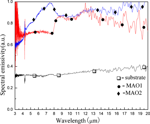
Spectral emissivity of substrate and MAO coatings
Conclusions
Ceramic coatings were prepared on Ti6Al4V in Na3PO4 electrolytic solution without or with nano-Fe2O3 particle addition. The following conclusions are drawn.
The nano-Fe2O3 particle was incorporated into the coating in MAO processing and sealed the discharge channel, which made the surface of the MAO coating much smoother.
The addition of the nano-Fe2O3 particle into the Na3PO4 electrolytic solution increased the thermal shock resistance of the MAO coating. After being subjected to severe thermal shocking for 50 cycles, little peeling-off of the coating occurred. The bonding strength has a small decrease after the thermal shock test, but the bonding strength is still higher than 27 MPa.
The addition of the nano-Fe2O3 particle into the Na3PO4 electrolytic solution increased the spectral emissivity of the MAO coating, which is caused by the presence of Fe2O3 in the structure of the coating.