
Abstract
The present study focused on reinforcing Al–Si–Cu alloy with a cast iron insert and using Zn–xAl–3Si–0·5Mg (wt-) intermediate alloys by the cast joining technique to take advantage of lightness and stiffness of the hybrid structure. The experimental set-up consisted of coating the insert using hot dipping method followed by immersing the coated insert into the Al melt and allowing the system to cool down to the room temperature. The quality of Al–Fe joints in terms of morphology, thickness, chemistry and microhardness was evaluated as a function of coating composition and immersion time in the Al melt. Characteristics of reaction layer at the coating/insert interface and its effects on the joint properties were determined using microstructural analysis and thermodynamic calculations. Combination of a suitable coating containing 27 wt-Al and optimised process parameters, including 1 min immersion time, resulted in the formation of an Al–Fe joint with promising characteristics.
Introduction
There is an increasing demand to use Al and its alloys in the powertrain automotive applications because of their low specific weight, which allows lightening of vehicles and subsequently improving the fuel efficiency. However, the relatively low mechanical strength and poor high temperature properties of Al alloys make them unsuitable for certain applications. The multimaterial (or hybrid) system is an alternative structure, where advantages of both Al alloys and ferrous alloys can be combined. In order to develop a hybrid structure with a weight saving potential and optimum properties, it is required to metallurgically join the Al to ferrous parts.1
There are very different joining methods varying from solid–solid state welding to solid–liquid state welding, but the integrity of the joint and its cost of fabrication significantly affect the selection of a joining procedure.2 Cast joining, where an Al alloy (matrix) is cast around an Fe based insert, is a good candidate because of its ability for mass production of near net shape components with complicated shape and design and particularly its low cost.3–6
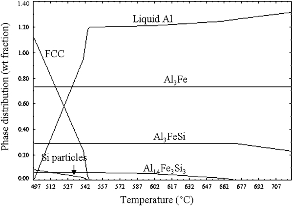
The bonding between Al and Fe could be physical, mechanical and/or chemical type.7 The interaction between Al and Fe is, however, a challenging concept due to their insolubility and the formation of hard and brittle intermetallic phases (IMPs) in the joint area, as shown in Fig. 1. The Al–Fe IMPs can be divided into two groups: high Fe content (FeAl and Fe3Al) and high Al content (AlFe2, Al5Fe2 and Al3Fe). Although all five IMPs are thermodynamically stable, all may not exist together in the reaction zone, which can be related to the difference in their nucleation and growth rates, different interdiffusion coefficients, etc.9 In order to make a sound joint with an acceptable durability and improved mechanical properties, it is required to control and to optimise the joint microstructure in terms of thickness, composition and morphology.10 The casting parameters including temperature and solidification time, the chemistry of the Al matrix and ferrous inserts, as well as the surface condition of the insert, are the most critical factors in the cast joining process. A short solidification time or the formation of an Fe oxide layer on the insert surface would prevent a thorough contact between the two metals. Even if a full contact occurs at the interface (using a special casting process such as squeeze casting or applying ultrasonic vibration into the melt during casting), the IMP layer forming at the interface is too thick and significantly degrades the joint properties.3–6,11 The use of an intermediate material could be a solution not only to improve the wettability of the Al alloy on the ferrous substrate but also to decrease the IMP layer thickness, resulting in an improvement in joint mechanical properties. The intermediate material could be employed in the form of a coating on the insert surface, and the characteristics of the reaction layer forming between the coating and the insert consequently affect the joint properties.12 An intermediate material should have two major characteristics: (1) a melting temperature lower than that of the Al alloy; and (2) be compatible with Al and Fe alloys and forms an alloying system with both without forming harmful phases.1
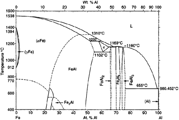
Al–Fe phase diagram8
Zn and its alloys are already being used as coatings to improve corrosion resistance of steel. Galvanising is the most common technique, and it involves dipping a steel product in a molten Zn (or Zn alloy) bath, during which the steel reacts with the liquid Zn and forms an Fe–Zn IMP layer between the steel and solidified Zn coating. Recently, many aspects of the galvanising technique and various types of Zn coatings have been studied;13–17 however, to the knowledge of the authors, little information is available on the use of Zn alloys as intermediate materials for the joining process of Fe and Al alloys. Mathieu et al. 18 18,19 published two papers on the laser braze welding technique to join an Al sheet to a steel sheet using a Zn–15Al filler. They reported that the filler chemistry affected the growth rate of IMPs, and a Zn based filler was selected due to the Al–Zn solubility and its low melting temperature, but the effect of filler on the joint quality was not discussed. The cast joining of a cast iron and/or an Al insert with the molten Al was also studied by Jorstad et al.;1 however, the main focus of his research was on the process parameters’ optimisation.
The phases forming at the interface of Fe and Zn at the bath temperatures between 450 and 490°C are solid solutions of α-Fe and η-Zn and IMP layers of Г (Г+Г1), δ and ξ, in the order given in Fig. 2. In reality, the reactions occurring in a galvanising system and mechanisms controlling the nucleation and growth of Fe–Zn IMPs are very complex due to the addition of different elements, mostly Al, into the Zn bath, impurities in the ferrous substrate, coincidence of different reactions at the interface, the fast kinetics of reactions and non-equilibrium conditions governing the process.16
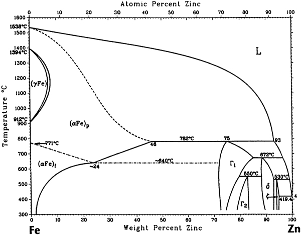
Fe–Zn phase diagram8
In the present study, joining of an Al–Si–Cu casting alloy to a compacted graphite cast iron insert (CGI) was investigated using two Zn based coatings as intermediate materials. The properties of the interlayers, especially the composition of interlayers forming at the interface between the coatings and the insert, and their influences on the joint quality were predicted using the FactSage thermodynamic modelling software. The effect of process factors such as immersion time in the Al melt and the solidification time on the joint microstructure was determined. In addition, the relationship between the joint microstructure and microhardness was established.
Materials and experiments
Materials
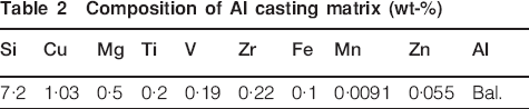
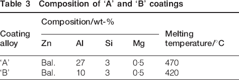
Materials were categorised into three groups: inserts (reinforcements), coatings (intermediate materials) and the surrounding alloy (matrix). The compacted graphite cast iron was cast in the form of plates, and the plates were then cut in small rectangular bars (75 mm height, 10 mm width and 2·5 mm thickness) as insert materials. The compositions of the cast iron and the Al casting alloy are given in Tables 1 and 2 respectively. Two Zn based alloys with Al contents of 27 wt- (alloy A) and 10 wt- (alloy B) were used as the intermediate materials. The composition and melting temperature of the coating alloys are shown in Table 3.
Composition of insert
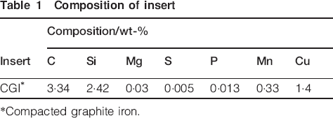
*Compacted graphite iron.
Composition of Al casting matrix (wt-)
Composition of ‘A’ and ‘B’ coatings
Experimental procedure
The experimental procedure consisted of three main stages: insert surface preparation, coating application and casting. The surface preparation includes cleaning, decarburising and flux treatment. The surface of cast iron samples was ground using SiC abrasive papers (600 grit) to obtain a fresh surface free from oxides and impurities. Then, the samples were cleaned with acetone. The decarburisation of inserts was performed in a molten salt bath containing a decarburising agent. The composition of the bath was 50 NaCl+50 Na2CO3 (wt-), and the melt temperature was kept constant at 850±5°C. The decarburising environment was provided by melting the salt in a resistance furnace using a graphite crucible. The bath temperature was kept constant at 900±5°C. The inserts were dipped into the liquid salt for a certain time, and the samples were allowed to cool down to the room temperature upon withdrawal from the bath. The decarburised inserts were brushed, rinsed with water and subsequently cleaned with acetone to remove any contaminant from the surface. Afterwards, the specimens were immersed in an aqueous sodium hydroxide solution (15NaOH) at 75±2°C for 15 s to chemically clean the surface, and finally rinsed in hot water and cleaned with acetone. The last step was the flux treatment. The flux was a mixture of salts, i.e. ZnCl2–15NaCl+3NaF.20 The salt was melted in a fireclay crucible in an induction furnace equipped with a powerful ventilation system. The melt temperature was kept at 480±5°C. The samples were immersed into the bath for 1 min to let a layer of flux cover the inserts, and then removed from the bath and immediately dipped into the Zn based coating bath.
The coatings were applied on the surface of the treated inserts. Approximately 200 g of each Zn based coating, alloys ‘A’ and ‘B’, was melted in the fireclay crucibles, and the melt temperatures were held at 550±5 and 500±5°C respectively. The treated inserts were dipped into the bath for various times (1, 3 and 5 min), then removed from the melt and either allowed to cool down to the room temperature or subsequently immersed into the molten Al matrix.
To simulate the casting operation, the coated inserts were immersed into the molten Al. The Al alloy was melted in a fireclay crucible, and the bath temperature was kept at 720±5°C. The inserts were immersed into the melt for different times of 30 s, 1 min and 10 min, and then the whole system (crucible containing Al melt and inserts) was removed from the furnace and allowed to solidify at room temperature.
Microstructural characterisation
After the coating and joining procedures, the specimens were sectioned perpendicular to the main axis, and the cross-sections taken from the samples were prepared for microstructural characterisations. The sample preparation was performed in the following sequence:
grinding from 120 to 1200 grit using SiC abrasive papers
final polishing with 0·05 μm Al2O3
ultrasonic cleaning in an acetone bath.
The microstructural analysis in terms of imaging, elemental analysis and thickness measurements was performed at the coating/insert interface, as well as at the coated insert/Al matrix interface (joint zone). A variable pressure scanning electron microscope (Hitachi S-3000N) equipped with an energy dispersive spectroscopy (EDS) detector (Oxford INCA System) was employed for imaging and elemental analysis. Backscattered electron imaging by the variable pressure scanning electron microscope was employed for measuring the thickness of the interface. The mean value of approximately 50–60 points around the interface is reported. The mechanical properties of the interface were evaluated based on the microhardness measurement using Clark LM-100AT Vickers indenter with 25 g load. The average microhardness value of four lines consisting of at least three points across the interface is reported as the final hardness value.
The thermodynamic analysis of the interactions between the CGI insert and the two Zn based coating alloys, as well as the reactions between the Zn based coated CGI and the molten Al alloy was conducted using FactSage 6·0 software.
Results and discussion
Thermodynamic analysis of interfacial reactions
As mentioned, the main objective of using a coating (or an intermediate material) is to form an inhibition layer between the Al melt and the cast iron insert in order to reduce the thickness of the reaction zone consisting of hard and brittle IMPs, to improve the wettability of the molten Al on the cast iron surface and consequently to increase the joint strength and performance.12 The microstructural studies and thermodynamic modelling were performed to optimise the process parameters in order to make a sound joint.
Interactions between insert and coatings
The chemistry of the reaction layer forming at the interface between the Zn based coating alloys and the CGI insert was studied using the FactSage calculations and microstructural characterisation.
Insert coated with alloy A
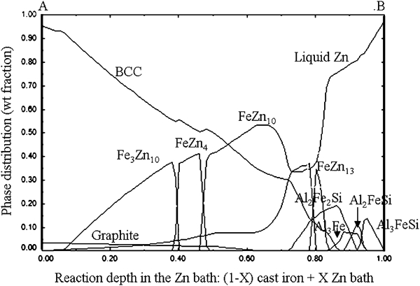
Figure 3 shows the formation of various reaction layers containing the Fe solid solution (bcc), the IMPs [Fe3Zn10 (Г), FeZn10 (δ), Al2Fe2Si, Al3Fe, Al2FeSi, Al3FeSi and Al14Fe3Si3] and the Zn solid solution moving from the CGI insert to the ‘A’ coating bath. It should be noted that lines A and B represent the unreacted cast iron and unreacted Zn bath respectively. The Y and X axes also display the weight fraction and the settlement sequence of the phases present within the insert/coating interface respectively.
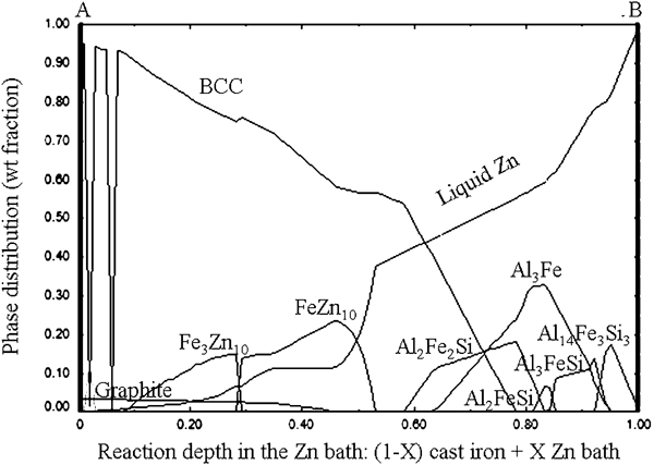
Reactions between CGI and ‘A’ coating alloy at 550°C
Figure 4 shows the typical elemental distribution across the interface between the ‘A’ coating alloy and the cast iron insert at 550°C after 5 min. The interface consisted of three main regions: the cast iron insert, the reaction layer and the overlayer, which is the solidified Zn alloy, as shown in Fig. 4a. EDS linescan further confirms the formation of different IMP layers at the interface. Aluminium distribution varies across the reaction layer and presents a sinusoidal profile, while the Fe concentration decreases, and the Si concentration increases and then decreases towards the overlayer respectively. Minor amounts of Mg and Zn are also present in the reaction layer. Figure 5 shows the map analysis of the interface proving that Zn did not diffuse into the reaction layer due to the inhibition effect of the Al–Fe–Si intermetallic layers and accumulated in the overlayer. Adjacent to the ferrous substrate, a layer containing mainly Al, Fe and Si with ∼1 μm thickness formed, as shown in Fig. 4. In the middle of the interlayer and close to the coating, different IMPs containing Al, Si and Fe are present. According to the observations, the ternary Al–Fe–Si IMPs with minor amounts of Zn and Mg mostly in the form of a solid solution in Al are predominant within the reaction layer.
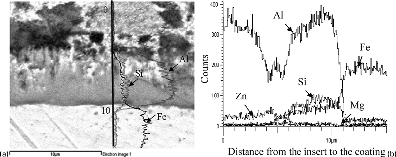
a image (SEM) and b elemental distribution across cross-section of ‘A’ coated cast iron at 550°C after 5 min
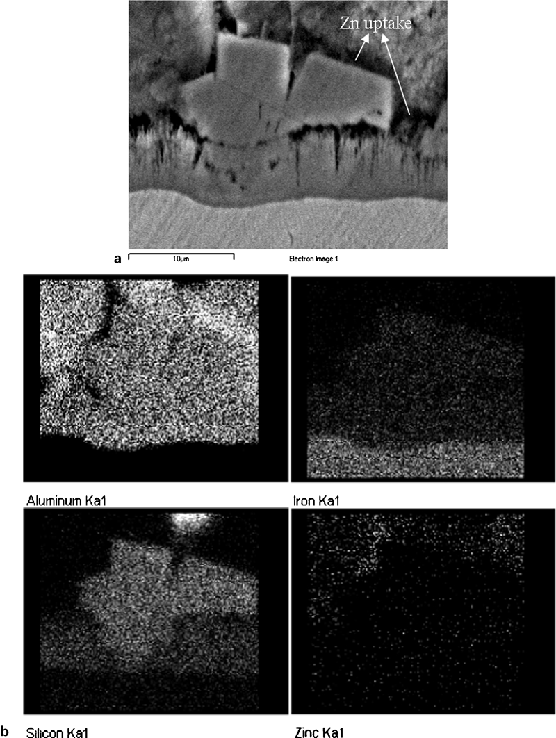
a image (SEM) and b typical EDS mapping of interface between ‘A’ coating alloy and cast iron insert at 550°C after 5 min
According to the map analysis (Fig. 5), no trace of Zn is observed at the interface using ‘A’ coating alloy, whereas the FactSage computations indicate the formation of thin layers of Fe–Zn IMPs at the coating/insert interface. This can be explained by, first, the very thin nature of Fe–Zn IMP layers, formed adjacent to the insert interface, which were not detected by the EDS, or, second, that the solidification process is not equilibrium while equilibrium conditions were assumed for the thermodynamic calculations. As a result of the equilibrium condition, the reaction time between the coating bath and the insert is assumed to be long enough for the onset of ‘outburst’ phenomenon and the formation of Fe–Zn IMPs at the interface between the Al–Fe–Si IMP layers and the CGI substrate. In fact, the reaction layer consisting of the ternary Al–Fe–Si IMPs acts as an inhibition layer against the formation of binary Fe–Zn IMPs at the interface.
According to Tang's study,17 it seems that a complex inhibition layer formed in two steps: first, the Al and Si uptake and the subsequent nucleation of Al–Fe–Si IMPs at the substrate interface, and, second, the growth of the inhibition layer by the diffusion of different species across the reaction layer. However, the inhibition is transitory, and there is an incubation period after which Zn atoms reach the Fe substrate, Fe–Zn IMPs nucleate and grow at the inhibition layer/Fe interface and as a result the ‘outburst’ or ‘inhibition layer breakdown’ happens.13 The inhibition layer is destabilised by the diffusion of Zn atoms along the short circuits, which are usually grain boundaries of the inhibition layer or the surface/particles interfaces.13 The dipping time in the coating bath, the bath temperature and the Al content of the bath are important factors in breaking the inhibition layer apart. The outburst formation could also be accelerated by other factors, such as the level of impurities of the grain size of the Fe substrate, as well as the formation of cracks in the inhibition layer due to growth stresses.13
Insert coated with alloy B
The formation of versatile IMP layers at the interface between the CGI insert and the ‘B’ coating bath at 500°C at equilibrium condition is shown in Fig. 6. The binary Fe–Zn IMP layers including Fe3Zn10 (Г), FeZn4, FeZn10 (δ) and FeZn13 (ζ); the binary Al3Fe; and the ternary Al–Fe–Si IMP layers form at the interface in that order from the cast iron to the Zn bath. The calculations are consistent with the microstructural observations. Elemental analysis of the interface using ‘B’ alloy also reveals the formation of high Zn bearing IMP layers at the interface, as presented in Fig. 7. This figure reveals the typical elemental distribution across the reaction layer forming at the interface between the cast iron insert and the ‘B’ coating alloy at 500°C after 3 min dipping time. The reaction layer consists of Al, Si, Fe and Zn as major elements and minor amounts of Mg, and transient metals such as Mn and Cu, particularly at the interface adjacent to the insert. The Fe gradient increases inwards the ferrous substrate, and those of Al, Si and Zn increases outwards the overlayer. The silicon concentration is the highest in the reaction layer, and Mg almost accumulates in the reaction layer from the coating bath.
Reactions between CGI and ‘B’ coating alloy at 500°C
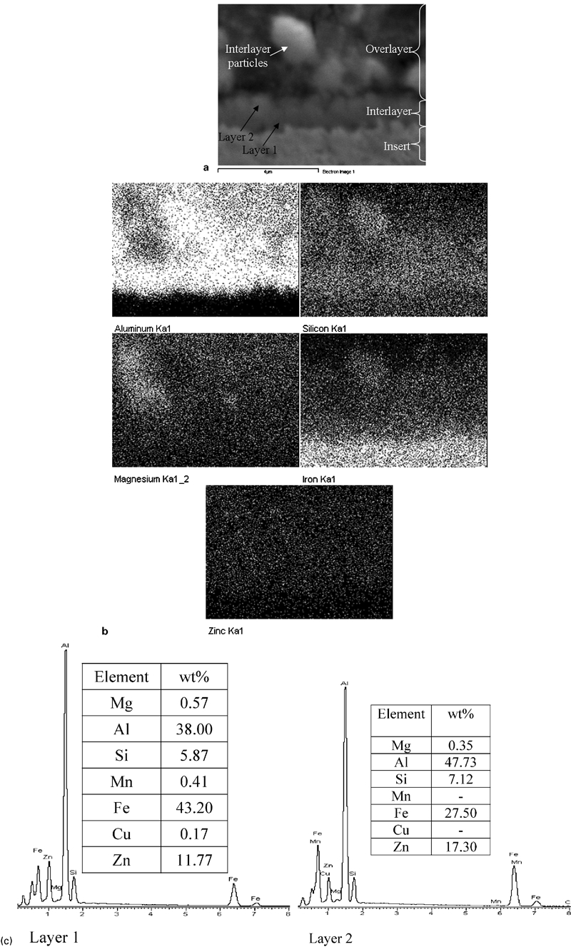
a SEM image, b EDS mapping of interlayer forming at interface between CGI insert and ‘B’ coating alloy at 500°C for 3 min, and c spectra and quantitative EDS patterns of layers 1 and 2
Reactions between coated insert and molten Al casting
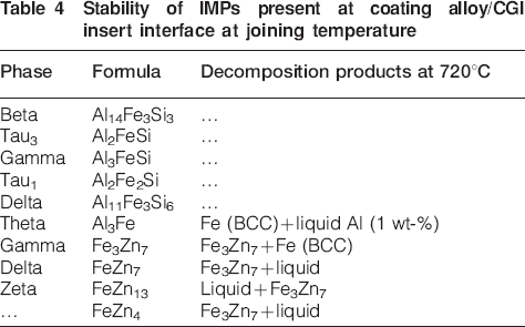
The objective of this part is to thermodynamically analyse the influence of the nature of the IMP layers forming at the coating/insert interface on the characteristics of the joint, particularly its composition. The interactions between the coated insert and the molten Al at the joining temperature (720°C) were studied using FactSage calculations. The stability of different IMPs present at the coating/insert interface at 720°C is given in Table 4. The ternary Al–Fe–Si IMPs are solid and stable, whereas the binary Fe–Zn IMPs decompose into a liquid phase and the Fe3Zn7 (Г) IMP at the joining temperature (720°C). According to the FactSage data, the binary Al3Fe IMP is not stable at 720°C, but its decomposition product is 99 wt- solid. Moreover, the Al–Fe phase diagram shows that this phase will be stable up to 1160°C (Fig. 1). A solid, stable IMP layer would play an inhibition role against the elemental diffusion across the interface and retard the growth rate of hard and brittle IMPs in the joint area. Therefore, the formation of Fe–Zn IMPs at the interface between the coating alloy and the insert is not desirable as a liquid phase could form at the joint zone. The formation of a thick, composite layer of ternary Al–Fe–Si IMPs at the interface, which is a characteristic of ‘A’ coating alloy, is more favourable for the Al–Fe joint fabrication.
Stability of IMPs present at coating alloy/CGI insert interface at joining temperature
The reaction products between the IMP layers present at the coating/insert interface and the Al melt were determined at 720°C using FactSage calculations. Results are presented for ‘A’ and ‘B’ coating alloys in Tables 5 and 6 respectively. The intermetallic layers shown in Figs. 5 and 6 were included in the thermodynamic calculations step by step. Reactions no. 7 in Table 5 and no. 8 in Table 6 represent the interactions between the coatings ‘A’ and ‘B’ and the CGI insert respectively. The difference between the weight fraction of the solid reactants fsr and the solid products fsp forming in the joint area represents the stability of the intermetallic layers forming at the coating/insert interface. This difference is inversely proportional to the amount of liquid Al generated at the joining temperature. The smaller difference represents more stable solid Al–Fe–Si IMPs and less chance of dissolving in the Al melt. With an increase in the amount of ternary Al–Fe–Si IMP layers at the coating/insert interface, the difference subsequently decreases, showing the favourable inhibition effect of the IMPs as a barrier against the diffusion of different species across the joint. However, with the formation of Fe–Zn IMPs at the coating/insert interface, this difference subsequently increases, indicating their undesired influence on the joint quality. In general, when ‘B’ coating is used, the difference between the solid reactants and the solid products (reaction no. 8 in Table 6) is greater than that using ‘A’ coating alloy (reaction no. 7 in Table 5). This shows that the IMP layers forming at the interface between the coating alloy ‘A’ and the insert are more stable in contact with the Al melt than those formed using the coating alloy ‘B’. Thus, the formation of Fe–Zn IMP layers at the coating/insert interface is not favourable to obtain a high quality joint. The solid products forming at the joint zone are Al3Fe and Al3FeSi phases; however, the morphology of the intermetallic layers was not studied. For example, FactSage predicted that two IMPs (Al3Fe and Al3FeSi) form in the joint area at 720°C, while the microstructural analysis revealed three IMP layers formed at the joint zone (Fig. 8). There are differences between the FactSage data and the experimental results. This can be due to the fact that the thermodynamic calculations were performed in equilibrium state and the kinetics of reactions was not considered. It could also be possible that a third IMP layer initially forms in the joint area during solidification, and then it might dissolve in the Al melt over the time. In both cases, the reaction kinetics plays a key role, which is not considered in the thermodynamic calculations. Figure 9 gives the Scheil cooling curve of the system, i.e. ‘A’ coated CGI in contact with the Al melt at 720°C, obtained by the FactSage computation. It can be seen that Al14Fe3Si3 or (Al4·7FeSi) IMP forms at the joint interface from the melt during the solidification. This confirms that there is a possibility of the formation of a third IMP layer during the solidification (nucleates at ∼670°C). However, there are still discrepancies between the experimental results and the FactSage data. It is observed that the three intermetallics are distributed across the joint interface rather than forming distinct layers, as seen in Fig. 9, and no explanation could be drawn about this difference at this point.
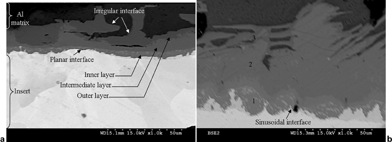
Typical morphology of joint zone between Al casting matrix and coated insert for a 1 min and b 10 min immersion times in Al melt (coating time: 5 min)
Scheil cooling curve of ‘A’ coated CGI in contact with Al melt
Reactions between IMP layers forming at interface between ‘A’ coated CGI and Al casting alloy at 720°C
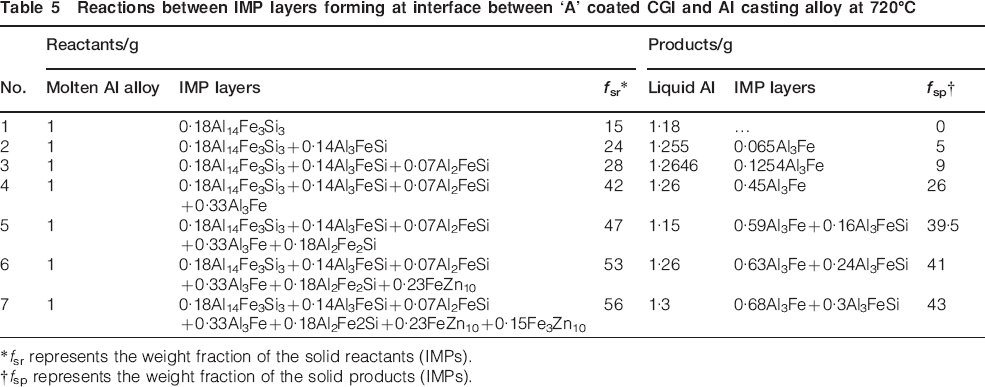
*fsr represents the weight fraction of the solid reactants (IMPs).
†fsp represents the weight fraction of the solid products (IMPs).
Reactions between IMP layers forming at interface between ‘B’ coated CGI and Al casting alloy at 720°C
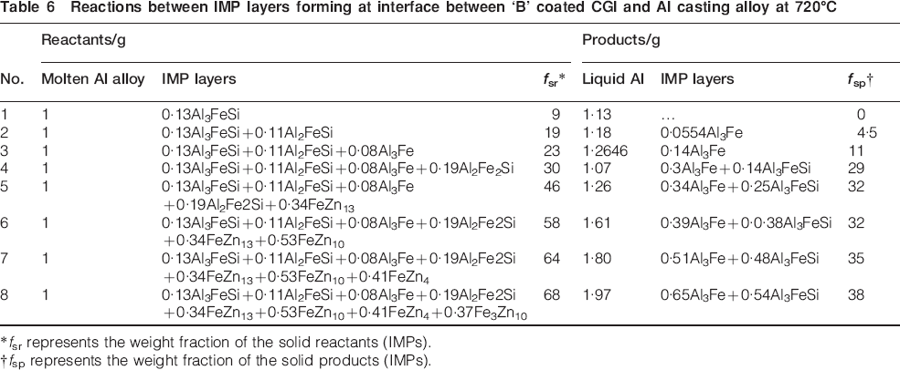
*fsr represents the weight fraction of the solid reactants (IMPs).
†fsp represents the weight fraction of the solid products (IMPs).
Microstructural analysis of joint
In a real casting application, a coated insert is placed in the mould, and then the Al melt is cast around the coated insert and cooled down to room temperature. For the present investigation, the short immersion times (30 s and 1 min) were selected to simulate the casting condition, and 10 min was chosen to study the growth behaviour of the interlayer forming in the joint area.
According to FactSage calculations, coating ‘A’ is a good potential intermediate material for the Al–Fe joint applications. The microstructural characteristics of the joint, obtained using coating alloy ‘A’ (including the morphology, thickness and chemical composition), the microhardness profile, as well as the effect of immersion time on the joint properties and growth behaviour of the interlayer are discussed for coating alloy ‘A’ in this section.
Morphology of joint
Figure 8 depicts the typical morphology of the joint zone between the coated insert and the Al casting matrix for 1 and 10 min immersion times. The morphology of the joint obtained for 30 s immersion time was very similar to that observed for 1 min immersion time. The joint area consists of the cast iron insert, a continuous, uniform interlayer and the Al matrix, as shown in Fig. 8a. The interlayer is composed of three sublayers, which are named as the inner layer, the intermediate layer and the outer layer beside the Al matrix. The morphology of the interlayer at the Al matrix interface is very irregular, while the interlayer at the cast iron interface is rather planar for short immersion times (30 s and 1 min) and becomes sinusoidal with increasing the time to 10 min. From the microstructural examination, it is evident that there is a growth direction for the interlayer, particularly for the intermediate and outer layers. This can be related to the absence of a uniform elemental distribution in the Al melt due to the presence of a specific convection path, which might lead to an ‘anisotropic diffusion’ of species across the interface, as reported by Zhang et al.21
Composition of joint
Figure 10 shows the typical chemical analysis of the joint forming between the ‘A’ coated insert and the Al casting matrix. According to the EDS analysis, the interlayer contains Al, Si and Fe as major elements in addition to impurities such as Zn in the form of a solid solution in Al. Three regions with different chemical compositions are also observed within the interlayer, which is consistent with the morphology of the joint, as observed in Fig 8. Silicon and Fe concentrations increase and decrease towards the Al matrix respectively, whereas the Al distribution gradient is rather even across the interlayer. Therefore, the binary Al–Fe and ternary Al–Fe–Si IMPs are expected to form close to the insert and Al matrix interfaces respectively. The IMPs’ correspondents to the sublayers’ chemistry are the binary Al3Fe compounds containing Si in the form of solid solution in Al, α-AlFeSi and β-AlFeSi ternary phases in that order from the insert to the Al matrix.
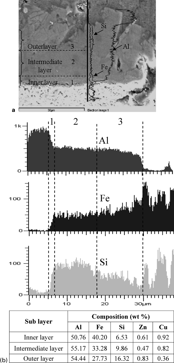
a image (SE) (coating alloy: ‘A’, coating time: 5 min, immersion time: 30 s) and b elemental distribution across joint zone forming between ‘A’ coated insert and Al casting matrix
Thickness of joint
Studies on the effect of immersion time on the growth trend of the sublayers within the joint interlayer showed that the inner layer slightly thickens with increasing contact time with the Al melt and the thickness of the intermediate layer significantly increases and the outer layer slightly decreases with time. The inner and intermediate layers become thicker due to the diffusion of species such as Al, Fe and Si across the interlayer. The outer layer becomes thinner due to the dissolution in the Al matrix. The growth rate of the inner layer is slower than that of the intermediate layer due to the inhibition effect of the intermediate and outer layers involving α-AlFeSi and β-AlFeSi phases respectively. However, the outer layer is the main inhibitor against the diffusion of elemental species towards the middle layer. It was reported that the presence of Si in the Al–Fe system resulted in the formation of a solid layer, which slowed down the diffusion and subsequent growth of the interlayer.3 In addition, the α phase has a bcc structure which is much more compacted compared to the monoclinic structure of the β phase.22 As a result, the diffusion rate of elemental species is slower through the α phase, and the growth kinetic of the inner layer is slower than that of the intermediate layer. It seems that the interlayer grows in two directions: downward to the insert and outward to the Al melt, which is a consequence of the higher diffusion rate of Al and Si than that of Fe. This can be explained by the fact the liquid state diffusion of smaller species is faster than the solid state diffusion of bigger elements. It is more probable that the intermediate layer containing the α phase grows further towards the Al matrix at the expense of Fe content of the outer layer due to the difficulty for the atoms such as Fe to diffuse through the α phase.
The effect of immersion time on the average thickness of the interlayer is shown in Fig. 11. It is seen that the thickness of the interlayer increases with time, but a slight decrease occurs from 30 s to 1 min, which could be due to the partial dissolution of the interlayer in the Al melt. According to studies of Viala et al. and Shih and Tu, 23 23,24 it is assumed that during the immersion of coated insert into the Al melt at 720°C, the dissolution and growth of the interlayer simultaneously happen at the interface, but its growth is more dominant. Dissolution occurs until the Al melt (beside the interface) becomes enriched in Fe, and at the same time, the growth takes place by the diffusion of species like Al, Si and Fe across the interface. The dissolution of the interlayer in the Al matrix depends on the diffusion and/or convection of Fe atoms in the Al matrix.3
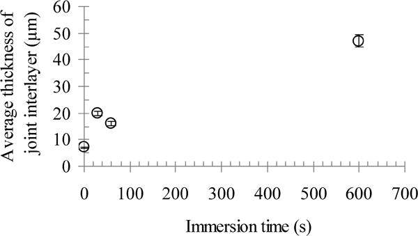
Effect of immersion time on thickness of joint interlayer
Beside the immersion time, the solidification time also affects the interlayer thickness as the diffusion continues at a slower rate during the solidification. Figure 12 shows the cooling curve of the Al casting alloy with the composition given in Table 2. It is seen in Fig. 12 that the solidification time of the alloy is ∼7 min. Therefore, the total time of the cast joining technique (7 min solidification time+the immersion time) is very long compared to that of high pressure die casting or squeeze casting processes, in which the solidification time is <1 min. With increasing cooling rate, it would be possible to gain a thinner interlayer, which is desired for making a high quality joint. The thickness of the interlayer should be decreased in order to enhance the mechanical strengths of the joint. It was reported that the tensile and shear strengths of the joints increased by reducing the interlayer thickness from 59 to 119 and from 39 to 59 MPa respectively.3 Overall, the formation of an interlayer with an average thickness of 16 μm obtained in the present study (for 1 min immersion time+5 min solidification time) is promising.
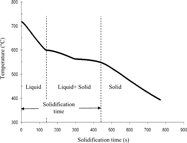
Cooling curve of Al casting alloy (in fireclay crucible with ∼200 g of melt)
Microhardness of joint
Figure 13 displays the microhardness profile of the joint using coating type ‘A’ for 1 min immersion time. According to the microhardness analysis, the interlayer, which is composed of different sublayers, has an average microhardness higher than the base materials, the Al matrix and the cast iron insert. It is also understood that the inner and intermediate layers are harder than the outer layer, which can be explained by the high concentration of soft elements, such as Al and Si in the outer layer, and of hard metals, particularly Fe in the inner layer, as seen in Fig. 9.
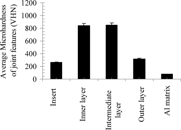
Average microhardness values of joint features using ‘A’ coatings for 1 min immersion time
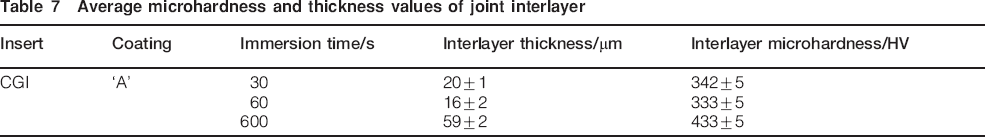
The effect of immersion time on the average microhardness of the joint is given in Table 7. It is seen that with increasing the immersion time from 30 s to 1 min, the joint microhardness slightly decreases (from 342±5 to 333±5 HV), and the mean value of microhardness of the joint significantly increases (from 333±5 to 433±5 HV) with further increasing the immersion time to 10 min. This can be ascribed to the formation of a thinner interlayer for short immersion times. There is a direct relationship between the thickness and microhardness values of the interlayer, i.e. the microhardness decreases with decreasing thickness. With increasing immersion time, in general, the harder sublayers (the inner and intermediate layers) become thicker, while the outer sublayer, which is softer, becomes thinner. In fact, the chemical reactions between the Al melt and the ferrous insert and the subsequent formation of a thick layer of hard and brittle IMPs at the interface increase the residual stresses in the joint area and, as a result, the joint could fracture at small strains.3
Average microhardness and thickness values of joint interlayer
Conclusions
The development of a bimetallic system using a CGI insert, an Al casting matrix and two Zn based coating alloys, called ‘A’ and ‘B’ (containing 27 and 10 wt-Al respectively) as intermediate materials through the cast joining technique, was investigated. Following coating the insert using the hot dipping method, the coated insert was immersed into the Al melt for different times, and then the whole system was allowed to cool down to the room temperature. The effect of two coatings on the quality of the Al–Fe cast joint was investigated using FactSage calculations. The influence of casting time on the joint microstructure and mechanical strength, particularly microhardness, was also examined. The following was concluded.
The IMP layers forming at the coating/insert interface could play an inhibition role against the diffusion of different species, mainly Al, Fe and Si, across the joint zone at the contact temperature between the Al melt and the insert. Coating alloy type ‘A’ leads to the formation of a composite, solid and stable reaction layer (AlxFey+AlxFeySiz), which acts as a barrier against the diffusion of species across the joint area and subsequently slows down the growth of hard and brittle IMPs. On the contrary, the formation of a thick layer of binary Fe–Zn IMPs, which are not stable at the joining temperature (720±5°C), would be detrimental to the joint quality for the coating alloy ‘B’.
There is a direct correlation between the mean thickness and microhardness values of the joint interlayer and the joining time. With decreasing immersion time from 10 to 1 min in the molten Al, the characteristics of the joint, including its thickness and microhardness, improved from 59±2 to 16±2 μm and from 433±5 to 333±5 HV respectively. This can be explained by the increase in the thickness of the sublayers containing hard metals like Fe and the decrease in the thickness of the soft sublayers containing mainly Al and Si with increasing time.
Coating alloy type ‘A’, Zn–27Al–3Si–0·5Mg (wt-), coupled with 1 min immersion time (in the molten Al) revealed a joint with promising properties in terms of morphology, thickness and microhardness.
Footnotes
Acknowledgements
The authors would like to acknowledge CANMET-MTL for providing raw materials and funding, and Professor I.-H. Jung for helping in the thermodynamic calculations.