
Abstract
The present paper demonstrates the development of a peening technique using recirculating shot accelerated by a water jet that can be used as a risk free treatment in power and chemical plants. Although it is important to increase the reliability of structural materials used in large scale structures, such as power and chemical plants, it is hazardous to treat these structures by general shot peening (SP) techniques because of the risk of sparks and dust explosions. In the present study, an SP technique using a water jet to accelerate shot has been developed, and the conditions under which it is used have been optimised in terms of nozzle geometry, standoff distance and amount of shot. In order to demonstrate the effect of SP, austenitic stainless steel Japan Industries Standards SUS316L was peened and evaluated in terms of its residual stress, fatigue strength and resistance to stress corrosion cracking.
Introduction
In large scale structures, such as power and chemical plants, it is necessary to ensure its long time operation by enhancing the fatigue strength and suppressing the stress corrosion cracking (SCC) in the materials from which the structure is made. Shot peening (SP), which utilises the impact generated by shot, can be applied to enhance the fatigue strength of mechanical components by introducing compressive residual stress on the surface layer.1–6 In order to carry out this treatment while the plant is in its operating condition, there must be no risk from sparks and dust explosions generated by shot colliding. In the present paper, we describe an SP technique in which the recirculating shots are accelerated by a water jet.
It is well known that the residual stress on the surface layer introduced by mechanical processing or heat treatment is one of the major factors that affects the fatigue strength and the resistance to SCC.7–13The SCC usually occurs when we have a material under tensile stress, including residual stress, in a corrosive environment. As it is difficult to improve a material's resistance to corrosion and reduce its exposure to the environment during operation, its resistance to tensile stress should be improved. This can be performed by introducing compressive residual stress on the surface for example using peening techniques, such as SP, cavitation peening14–17 or laser peening.18–20
In general, air blast systems and centrifugal blast systems are used for accelerating shot. The shots hit the surface in high velocity and broke due to colliding. 21 21,22 There is a possibility that sparks and dust explosions generate in such situation. 23 23,24 For this reason, general SP treatment is always exposed to risk of sparks and dust explosions. In order to avoid the risk of sparks and dust explosions caused by solid body collisions, it is essential to use a dust collector and a separator. As those systems make the SP apparatus larger, it becomes more difficult to treat some structures. Therefore, an alternative technique for accelerating shot to replace air blast systems or centrifugal blast systems needs to be used. Ultrasonic SP,25–29 which utilises ultrasound for accelerating shot, is smaller than those using air blast systems and centrifugal blast systems because the apparatus does not require a dust collector or separator. Although the ultrasonic SP apparatus is small and easy to carry, it is likely that sparks and dust explosions might be generated in the apparatus housing during treatment. An SP technique using a water jet to accelerate shot can be more efficient in terms of energy since water is an incompressible fluid and more closely to shot compared with air regarding specific gravity. Although a peening technique that uses glass shot accelerated by a water jet has been applied for practical use,30 the glass shot inevitably becomes industrial waste. With an SP technique in which metallic shot is accelerated and recirculated by a water jet, such as the one developed in the present paper, the generation of dust can be avoided, and the equipment can be small and portable since neither a dust collector nor a separator is required. This SP equipment is easy to carry, and risk free treatment can be carried out on structures where peening is required.
It is important to increase the peened area to treat large scale structures efficiently. A water jet injected through a single nozzle throat can treat only the area around the centre of the water jet. The peened area can be increased by having multiple holes in the nozzle. In the present study, in order to expand the peened area, a nozzle with three holes was used.
Experimental
Figures 1–3 show schematic diagrams of the recirculating SP apparatus, the transverse schematic and photograph of the peening head. Figure 4 shows a schematic diagram of the nozzle. The shots were accelerated by a water jet pressurised by a plunger pump. The injection pressure of the water jet was set to 8 MPa during treatment. The shots were loaded in the chamber before water injection and circulated in the chamber after water injection. In order to circulate the shots in the chamber after collision, four 1 mm diameter drain pipes were placed in the upper part of the peening head. The circulated shots were accelerated again by the water jet. The peening head was moved along the guide using the motor shown in Fig. 1. In order to reduce friction between the peening head and the specimen, a sponge sheet was placed at the bottom of the peening head. The shots used in the present study were metallic particles made of Japan Industries Standards (JIS) SUS440C. The diameter of the shots was 3·2 mm in order not to get stuck at the bottom of the peening head.
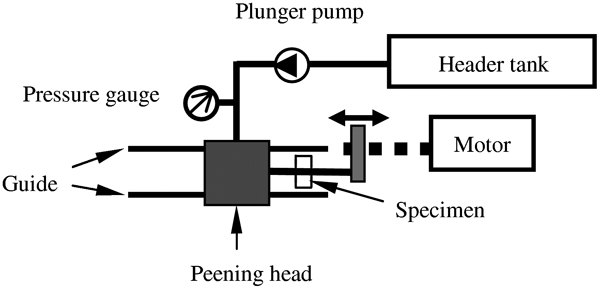
Schematic diagram of recirculating shot peening (SP) apparatus
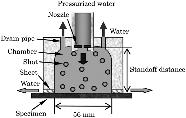
Transverse schematic of peening head for recirculating SP
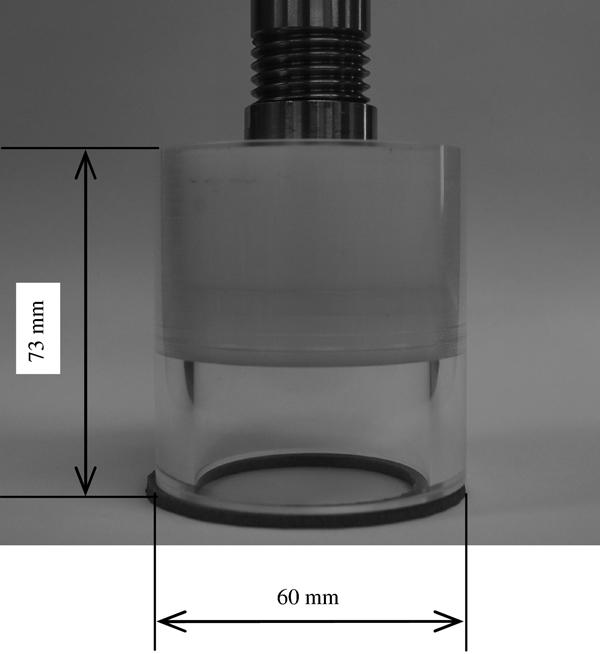
Photograph of peening head for recirculating SP
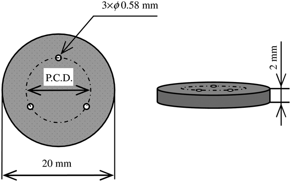
Nozzle for water jet with three holes
In order to find the optimum peening conditions, the pitch circle diameter (PCD) and the standoff distance were varied as nozzles with three 0·58 mm diameter holes, as shown in Fig. 4, were used. The PCD was defined as the diameter of an imaginary circle drawn through three holes of the nozzle. The standoff distance is defined by the distance between the nozzle and the specimen. The PCD and the standoff distance were varied between 10, 12, 14, 16 and 18 and 27, 30, 35, 40, 45, 50, 55 and 60 mm respectively. In order to determine the optimum conditions, the peened areas of specimens of stainless steel JIS SUS316L painted black before peening were evaluated by measuring the grey scale value in the areas where paint had been removed by peening. In the present paper, the grey scale value, i.e. brightness, was defined so that the value of black was 0, the value of white was 255 and the value of grey is varying from 1 to 254. When the shots hit the specimen painted black, the paint was removed, and the value of grey scale increased. In order to treat the surface, the peening head was scanned in the width direction of the specimen by motor, as shown in Fig. 1. The processing time per unit length tp was 2 s mm−1. The amount of shots loaded in the chamber numbered 300. After finding the optimum PCD and standoff distance, the variation in the peened area with the amount of shots was evaluated. The amount of shots was varied between 0, 100, 300, 500, 600, 700, 800, 900 and 1000. In this experiment, there is a possibility that the grey scale value was saturated. In order not to saturate the grey scale value, the processing time per unit length was changed from 2 to 1 s mm−1. The dimensions of the specimens were 95 mm in length, 35 mm in width and 3 mm in thickness. In the following tests, the optimised conditions developed above were used for peening.
The residual stress σR introduced into the specimens in the longitudinal direction was measured using an X-ray diffraction method employing an X-ray tube with a Cr target operated at 30 kV and 8 mA. The angle of the solar slit was 1°, and the slit width was 4 mm. The diffractive angle 2θ was varied from 143·5 to 153·5° in steps of 0·2°, and the sample was exposed to X-rays for 4 s in each step. A scintillation counter was used as a detector and placed at angles of ψ = 0, 22·8, 33·2, 42·1 and 50·7°, where ψ is the angle between normal to the specimen surface and normal to the diffractive face. The diffractive plane used was the (3 1 1) plane of γ-Fe, the diffractive angle 2θ without strain was 148·5° and the stress factor for this method was −369·5 MPa/degree. The diffractive angle was determined by a half value width method, and the residual stress was calculated by a sin2 ψ method, i.e. the gradient of the line from the five points on the 2θsin2 ψ diagram using a least square method. In order to determine the optimum processing time from the results of residual stress measurements, the processing time per unit length was varied from 0 to 5 s mm−1, and the residual stress was evaluated by the sin2 ψ method. After that, the sin2 ψ method with electropolishing was conducted to evaluate the depth distribution of the compressive residual stress introduced by SP with water jet. The measurement residual stress was corrected using the Moore and Evans compensation equation.31 The dimensions of the specimens made of JIS SUS316L for measurements of the residual stress were 200 mm in length, 100 mm in width and 6 mm in thickness in order not to release the introducing residual stress by curvature generated by plastic deformation at the surface by SP. Figure 5 shows the shape of the specimens used for the plate bending fatigue test. In order to suppress the effect of heating during the test on the fatigue process, the thickness of the specimen was 2 mm. In this test, the bending stress was generated by eccentric rotation set to 700 rev min−1. The stress ratio was −1.
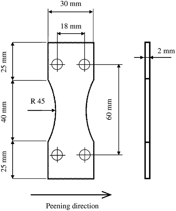
Geometry and dimensions of specimens for plate bending fatigue test
In order to evaluate the resistance to SCC, an SCC test was conducted. The dimensions of the specimens for this test were 95 mm in length, 30 mm in width and 3 mm in thickness in consideration of the size of the SCC test apparatus. An angle grinder was used to introduce tensile residual stress before SP with water jet, and the specimens peened by SP with the water jet after grinding were compared with the specimens treated by the angle grinder only. Figure 6 shows the apparatus for the SCC test. The SCC resistance of the stainless steel can be evaluated using a corrosive solution. The corrosive solution used in the present study was 30 calcium chloride in water at 353 K. The pH of the solution was adjusted to 3·5, and the exposure time was 48 h. After exposure, the surfaces of the specimens were examined using a microscope in order to evaluate the cracks generated by the corrosive environment.
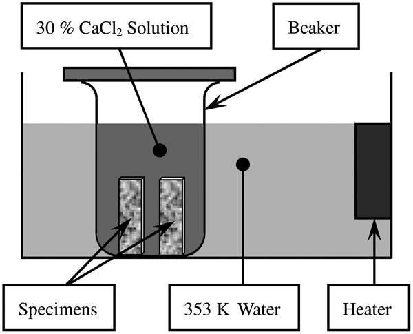
Stress corrosion cracking test apparatus
Results and discussion
Optimum peening conditions
In order to find the optimum PCD and standoff distance, Fig. 7 shows the integrated grey scale value as a function of standoff distance. The integrated grey scale value at each PCD size was evaluated three times, and the data in Fig. 7 were averaged values with standard deviation. As shown in Fig. 7, in the case of PCD = 10, 12, 14 and 18 mm, the maximum value is ∼3·2×104, and there are no clear peaks. On the other hand, in the case of PCD = 16 mm, the maximum value is larger than in the other cases, and there is clearly a peak at s = 45 mm. Because the PCD is closely related to the distribution of the water jet velocity, only the area around the centre of the water jet was peened in the case of short standoff distances, and the impact generated by the shot was smaller in the case of long standoff distances. For this reason, there is an optimum standoff distance for expanding the peened area, and the value of s was 45 mm.
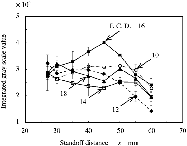
Integrated grey scale value versus standoff distance for various values of PCD
In order to determine the most appropriate amount of shots, Fig. 8 shows the integrated grey scale value as a function of the amount of shots loaded in the chamber. In Fig. 8, the integrated grey scale value increases along with increasing number of shots until 700 and then decreases above 700. The number of times that the shot hits the specimen increases when the amount of shots is increased. The effect of the interaction between each shot also increases with the increased amount of shots. For these reasons, there is an optimum amount of shots. In the case of the proposed peening technique, in which there are three holes in the nozzle, the optimum PCD, standoff distance and number of shots were determined to be 16 mm, 45 mm and 700 respectively. In the following experiments, the specimens were peened using these optimum conditions.
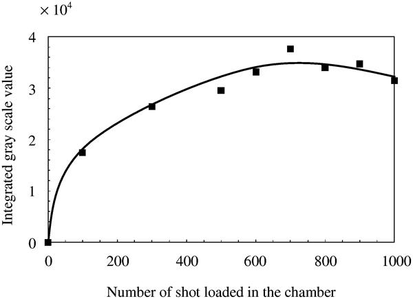
Integrated grey scale value versus number of shots loaded in chamber
Introduction of compressive residual stress
Figure 9 shows the residual stress σR introduced at the surface by SP with water jet and water jet without shots as a function of the processing time per unit length. In Fig. 9, the compressive residual stress introduced by SP with water jet saturates after 1 s mm−1 in consideration of measurement error. From this result, in order to keep the processing time to a minimum for practical use, the processing time used in following experiments was set to 1 s mm−1. In the case of the water jet, the surface residual stress was almost 0 MPa in each processing time. In general water peening or water jet peening, water is injected in much higher pressure. 32 32,33 On the other hand, water was injected at only 8 MPa in the present study, and it does not have the ability to cause workhardening, which is needed to introduce compressive residual stress at the surface layer contrary to the shot. It indicates that compressive residual stress was introduced by impact of not water jet but shot.
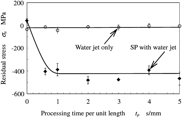
Introduction of compressive residual stress by SP with water jet
Figure 10 shows the residual stress σR introduced by SP with water jet as a function of the depth from the peened surface z of a specimen peened for a processing time of 1 s mm−1 and a non-peened specimen. As shown in Fig. 10, although the residual stress in the case of the non-peened specimen is almost 0 MPa, the compressive residual stress on the surface introduced by SP with water jet is 380 MPa in compression, increasing to 520 MPa between 50 and 100 μm. The compressive residual stress slowly decreases with increasing depth and has been introduced up to a depth of ∼600 μm. This result shows that this SP with water jet technique can be used to introduce compressive residual stress up to depths of 600 μm.
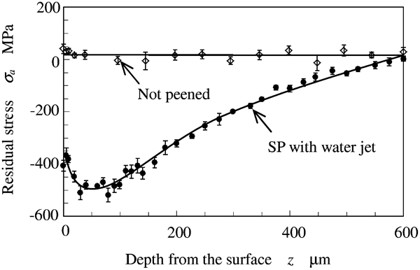
Distribution of introduced compressive residual stress by SP with water jet
Enhancement of fatigue strength
Figure 11 shows the applied bending stress as a function of the number of cycles to failure Nf with and without the proposed SP. As the applied bending stress is decreased, Nf for the specimen treated by SP with water jet increases until 2×10⁶cycles, as does Nf for the case of the non-peened specimen; however, for Nf of >107cycles, the applied stress of the specimen treated by SP with water jet, which can be defined as its fatigue strength, is larger than that of the non-peened specimen. The fatigue strength of the non-peened specimen is 279 MPa calculated using Little's method,34 while that of the specimen treated by SP with water jet is 350 MPa. The compressive residual stress introduced up to 600 μm deep by SP with water jet is one of the major factors for this enhancement. This result indicates that the proposed SP technique can enhance the fatigue strength of a JIS SUS316L specimen by 25 compared to that of a non-peened specimen.
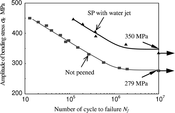
Enhancement of fatigue strength by SP with water jet
Improvement in SCC resistance
Figure 12 shows the surfaces of the specimens after the SCC test. Before the SCC test, both specimens were treated by an angle grinder, and then one specimen was treated by SP with water jet. In the case of the specimen without SP, many cracks of ∼50 μm developed around the pitting corrosion caused by the corrosive environment. On the other hand, in the case of the specimen with the proposed SP, no cracks were caused by the corrosive environment. From this result, cracks generated in a corrosive environment can be suppressed by introducing compressive residual stress by SP with water jet, indicating that the proposed SP technique might suppress SCC.
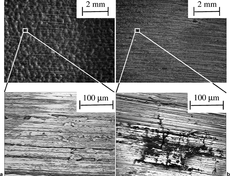
Surfaces with and without SP with water jet after exposure to corrosive solution
Conclusions
A method of SP in which the shot is accelerated by a water jet, thus avoiding sparks and dust explosions, was developed. The effects of the proposed SP technique on the fatigue strength, the introduction of the compressive residual stress and the resistance to SCC in austenitic stainless steel JIS SUS316L were evaluated. The results obtained are summarised as follows.
The operating conditions for this SP technique were optimised by evaluating the peened areas of several specimens.
Compressive residual stress was introduced by this technique into the surface of stainless steel to a depth of ∼600 μm.
The technique can be used to enhance the fatigue strength of JIS SUS316L by 25.
The technique can be used to suppress the initiation of SCC in JIS SUS316L in a corrosive environment.
Footnotes
Acknowledgements
The present work was partly supported by the Japan Society for the Promotion of Science under Grant in Aid for Scientific Research (A) no. 20246030 and Research Fellow 22. 2438.