
Abstract
The Mg–Li alloys with Li content of 5–11 mass- will exhibit a dual phase structure of α (hcp) and β (bcc) phases. These dual phase Mg–Li alloys have excellent formability, as well as extra low density. However, the Mg–Li alloys still have disadvantages of poor corrosion and wear resistance. In the present study, the AlN films deposited on Mg–Li alloy by radio frequency magnetron sputtering were investigated. The microstructure, surface morphology and corrosion resistance of the AlN films were examined by means of X-ray diffraction, SEM, TEM, and potentiodynamic polarisation. Experimental results show that deposited AlN films exhibit an amorphous structure, which can effectively improve the corrosion resistance of Mg–Li alloy. Meanwhile, the sputtering parameters, such as the radiofrequency power and working pressure, are found to have significant effects on the corrosion behaviour of deposited AlN films on Mg–Li alloy.
Introduction
Many methods, such as physical vapour deposition and chemical vapour deposition (CVD), have been utilised to coat protective films on metals and alloys.1–6 The CVD techniques, including the conventional CVD or plasma enhanced CVD, have been widely used to produce dense films with excellent homogeneity for large area substrates. However, the deposition temperatures in the CVD processes are so high that the CVD techniques cannot be applied to the film coating on the metal substrates with low melting temperatures, such as the Mg–Li alloys. Therefore, the physical vapour deposition methods, due to their low deposition temperature and easy control of processing parameters, are popular for coating films on these substrates with low melting temperatures.
Some corrosion behaviours of Mg alloys have been previously reported. The pitting corrosion tends to form on the alloy's surfaces with the presence of Cl–, and the oxidation films form easily when the alloys are in alkaline solution.7–11 However, few papers have reported the corrosion behaviours and protective coatings of Mg–Li alloys. In the present study, the radiofrequency (rf) magnetron sputtering technique was employed to deposit protective AlN films on the Mg–Li alloys. The surface morphology, crystal structure and corrosion resistance of the Mg–Li alloys without and with deposited AlN films are examined. The effects of sputtering parameters, including the rf power and working pressure, are also discussed in this article.
Experimental
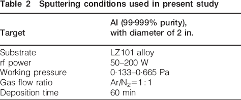
Melting of Mg–Li alloys (LZ101 is a representative alloy in the present study) was processed in a high frequency electrical induction furnace with vacuum capability and inert argon gas. The as cast LZ101 alloy was analysed with induction coupled plasma atomic emission spectrometry apparatus, and its chemical compositions are shown in Table 1. The casting rod with a diameter of 200 mm was hot extruded to plates with 10 mm thickness at 220°C. These extruded plates were then hot rolled to 3 mm in thickness at 220°C. Specimens for various testing were cut from these hot rolled plates and then mechanically polished with SiC abrasive paper down to P1200 grit. The AlN films were deposited on LZ101 alloy by rf magnetron sputtering. Table 2 shows the sputtering conditions used in the present study.
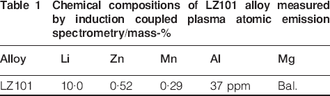
Chemical compositions of LZ101 alloy measured by induction coupled plasma atomic emission spectrometry/mass-
Sputtering conditions used in present study
A scanning electron microscope SEM was employed for observation of the film's surface and cross-sectional morphologies. X-ray diffraction (XRD) tests were carried out on a Rigaku glancing incident angle diffraction using Cu Kα radiation. Transmission electron microscopy (TEM) observations were conducted with a Philips Tecnai F20 G2 electron microscope operating at 200 kV. The corrosion behaviours of the coated and uncoated specimens were evaluated by anodic potentiodynamic polarisation tests at ambient temperature. A potentiostat/galvanostat with a corrosive medium of 3·5 wt-NaCl solution was used to simulate the aggressive aqueous environment containing chloride ions. A standard saturated calomel electrode was used as a reference, with platinum as a counter or auxiliary electrode. In all cases tested, the working areas were 1 cm2. The electrode potential was raised from −1·1 to −2 V at a scanning rate of 2·0 mV s–1.
Results and discussion
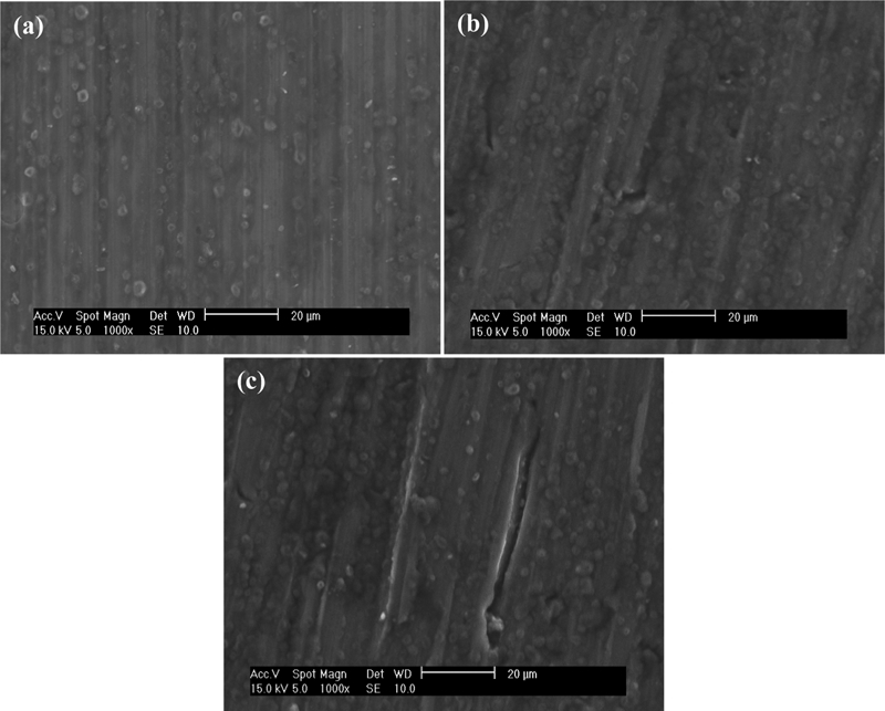
Figure 1 shows the SEM images of the LZ101 substrate and with AlN films deposited at rf powers of 50–200 W respectively. The working pressure of 0·133 Pa and the N2/Ar ratio of 50 are maintained during the sputtering process. As shown in Fig. 1a, the as ground specimen exhibits many obvious defects, such as scrubbed traces, voids, etc. These surface defects are covered gradually during the deposition of AlN films. Hence, the whole specimen surface has been conformably covered by the AlN film deposited at rf power of 150–200 W, as shown in Fig. 1d and e. This result indicates that even though the bare LZ101 alloy has many serious surface defects, they can be smoothly renovated and entirely protected by the deposited AlN films. Furthermore, Fig. 2 shows the cross-sectional morphologies of deposited AlN films at rf powers of 50–200 W and a working pressure of 0·133 Pa. The deposition rate of AlN films is found to increase with increasing rf power, as shown for the film's thickness in Fig. 3. This result is ascribed to that the increase in rf power will increase the quantity of ejected atoms from the target, hence increasing the deposition rate. It is worthy to mention that the interfaces between the AlN films and LZ101 substrate are quite smooth, except that deposited at an rf power of 200 W. These features will significantly affect the alloy's corrosion resistance, as discussed later.
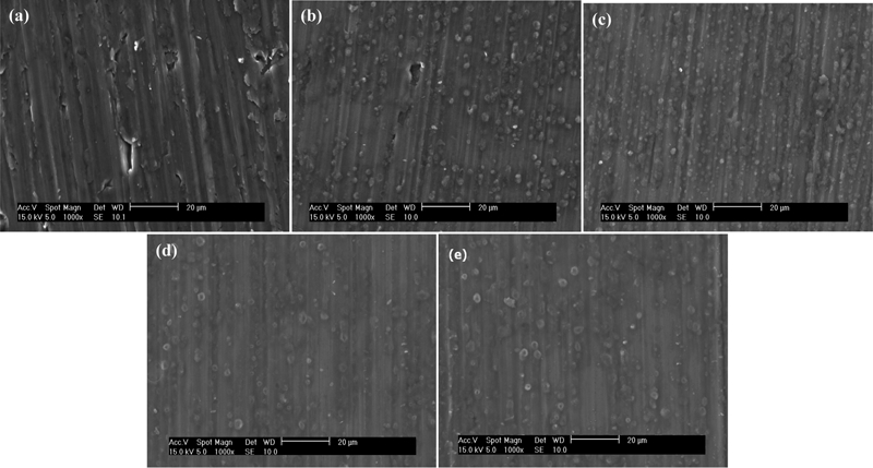
Surface morphologies of a LZ101 substrate and with AlN films deposited at various rf powers of b 50 W, c 100 W, d 150 W and e 200 W
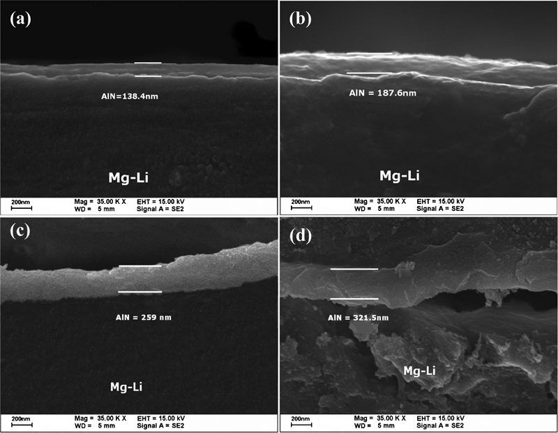
Cross-sectional images of AlN films deposited at various rf powers
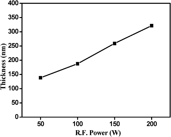
Thicknesses of AlN films deposited at various rf powers
Figure 4 shows the XRD patterns of the LZ101 specimens without and with deposited AlN films at rf powers of 50–200 W and a working pressure of 0·133 Pa. All the diffraction spectra in Fig. 4 exhibit a typical dual phase structure of α (hcp) and β (bcc) phases of LZ101 alloy. This feature is reasonable because the AlN films are amorphous. The XRD peaks are mainly from the diffraction of LZ101 substrates. Figure 5 shows the cross-sectional TEM images and diffraction pattern of the LZ101 specimen with deposition of AlN film. The diffraction pattern in Fig. 5b also indicates that the AlN layer exhibits an amorphous structure. In Fig.5a, the film thickness is ∼230 nm. This cross-sectional microstructure also reveals that the AlN film exhibits a smooth, pinhole free structure and has an excellent conformity with the LZ101 substrate.

X-ray diffraction patterns of LZ101 substrate and with AlN films deposited at various rf powers
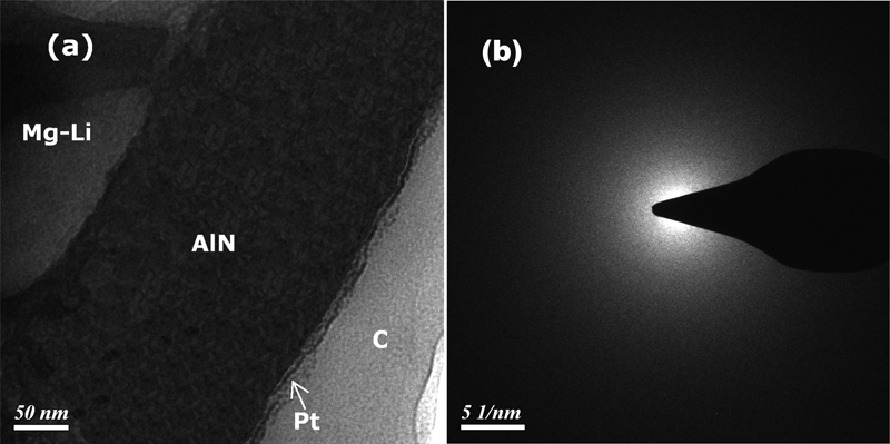
Analysis (TEM) of deposited AlN film on LZ101 alloy
The potentiodynamic polarisation curves of the LZ101 substrate and with AlN films deposited at various rf powers are shown in Fig. 6. The corrosion potential Ecorr and current density Icorr are determined by Tafel plot. The LZ101 specimen with AlN film deposited at a lower rf power, such as 50 W, cannot effectively improve the alloy's corrosion performance. This comes from the fact that the AlN film deposited at rf power of 50 W is too thin to fully cover the whole specimen surface. The retained surface defects will introduce the galvanic cell effect12 and accelerate the corrosion. With increasing rf power up to 150 W, the deposited AlN film has enough thickness to conformably cover the whole specimen surface. Hence, the alloy's corrosion performance is significantly improved. It has much lower Icorr and higher Ecorr than the LZ101 substrate. This result is consistent with the reported study13 that a dense coating can provide a high corrosion resistance in corrosive aqueous media. However, for the AlN film deposited at rf power of 200 W, it exhibits a worse corrosion performance because the interface between the AlN film and LZ101 substrate has many porosities. These porosities will degrade the film's ability for protecting the LZ101 substrate.
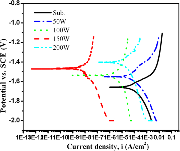
Potentiodynamic polarisation curves in 3·5NaCl solution for LZ101 substrate and with AlN films deposited at various rf powers
It is valuable to understand the effects of working pressure on the AlN films deposited on the Mg–Li alloy. Figure 7 shows the SEM images of the LZ101 specimens with AlN films at working pressures of 0·133, 0·399 and 0·665 Pa respectively. The rf power of 150 W and the N2/Ar ratio of 50 are maintained during the sputtering process. Figure 8 shows the cross-sectional morphologies of deposited AlN films at an rf power of 150 W and working pressures of 0·133, 0·399 and 0·665 Pa. By carefully examining these images, it can be seen that the AlN film deposited at a lower working pressure will exhibit a better quality, namely, more surface defects are observed for the AlN films deposited at higher working pressures, such as 0·399 and 0·665 Pa in the present study. This phenomenon is due to a higher working pressure that will shorten the mean free path of sputtered atoms. Hence, less sputtered Al atoms can reach the substrate and the dynamic energy of the deposited atoms is smaller. These phenomena will make the AlN films have more surface defects. Furthermore, the deposition rate of AlN films decrease with increasing working pressure, as shown in Fig. 9. This result is ascribed to less sputtered atoms that reach the substrate and reduce the growth rate. The potentiodynamic polarisation curves of the LZ101 substrate and with AlN films deposited at various working pressures are shown in Fig. 10. As shown in Fig. 10, the LZ101 specimens with AlN films deposited at higher working pressures exhibit worse corrosion performance. This phenomenon may be ascribed to that the AlN film deposited at a high working pressure has a lot of surface defects.
Surface morphologies of LZ101 specimens with AlN films deposited at various working pressures
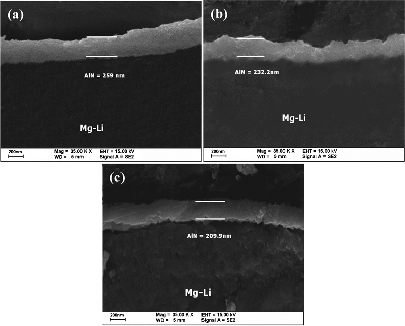
Cross-sectional images of AlN films deposited at various working pressures
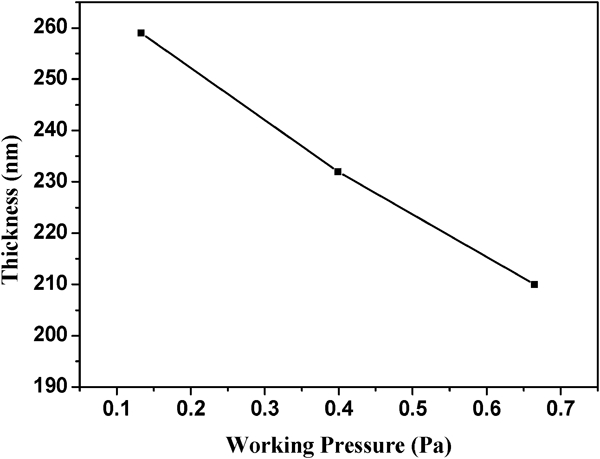
Thicknesses of AlN films deposited at various working pressures
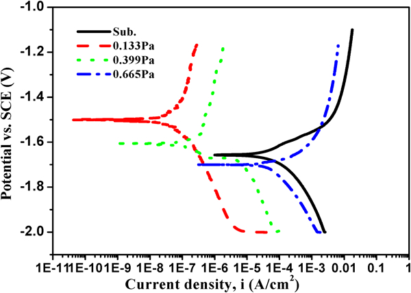
Potentiodynamic polarisation curves in 3·5NaCl solution for LZ101 substrate and with AlN films deposited at various working pressures
Conclusions
The important conclusions in the present study are summarised as below:
The AlN films have been successfully deposited on the LZ101 alloy by rf magnetron sputtering. The AlN films exhibit an amorphous structure.
The LZ101 alloy with AlN film deposited at a working pressure of 0·133 Pa and rf power of 150 W exhibits a best corrosion performance among all the tested specimens, namely, the lowest Icorr and highest Ecorr. This feature is ascribed to the excellent coverage and conformity of the AlN film on the LZ101 substrate.
Footnotes
Acknowledgements
The authors are pleased to acknowledge the financial support of this research by the National Science Council (NSC), China, under grant nos. NSC 96-2221-E-035-044-MY3 and NSC 97-2221-E-002-034-MY3.