
Abstract
Starting about 1920 it becomes easier to track the growth of bearing materials technology. Until 1955, with few exceptions, comparatively little progress was made in this area. AISI 52100 and some carburising grades (AISI 4320, AISI 9310) were adequate for most applications. The catalyst to quantum advances in high-performance rolling-element bearing steels was the advent of the aircraft gas turbine engine. With improved bearing manufacturing and steel processing together with lubrication technology, the potential improvements in bearing life can as much as 80 times that attainable in the late 1950s or as much as 400 times that attainable in 1940. This paper summarises the chemical, metallurgical and physical aspects of bearing steels and their effect on rolling bearing life and reliability: the single most important variable that has significantly increased bearing life and reliability is vacuum processing of bearing steel. Differences between through hardened, case carburised and corrosion resistant steels are discussed. The interrelation of alloy elements and carbides and their effect on bearing life are presented. An equation relating bearing life, steel hardness and temperature is given. Life factors for various steels are suggested and discussed. A relation between compressive residual stress and bearing life is presented. The effects of retained austenite and grain size are discussed.
Introduction
Jacob Rowe applied for a British patent in 1734 for a rolling-element bearing. In his patent he defined the advantages of such a bearing. Rowe stated that with the adoption of such bearings to …‘wheel carriages… one Horse now will do the labour of two… and … I will suppose that there will be occasion to employ only twenty thousand Horses … instead of the 40,000 existing in the United Kingdom at an annual savings of 1,095,000 pounds per year.’ Kelly1 in writing about Rowe said ‘that he was not able to find historical records that reported such sudden prosperity had occurred. As a result, he concluded that that the cost for keeping a horse that was not working was as much as it was for one that was in fact working.’ Things really have not changed in over 275 years.
The rolling bearing materials used in Jacob Rowe's era would have been wood, bronze and iron. Modern rolling-element bearing steel and metallurgy do not begin until about 1856 with the disclosure of the Bessemer process. In this process air is blown through molten pig iron to produce a relatively high grade of steel. This was followed 10 years later by the invention of open-hearth melting, which further improved quality and made steel far more accessible to industry. Bicycle bearing manufacturers were quick to take advantage of this new material. However, because heat treatment of steel was still an art known only to a few, most rolling-element bearings were probably made of unhardened steel. In 1879, British patent 869 was issued to J. Harrington and H. Brent for a hardened steel bushing, or inner shaft, fitted with a groove for balls. About the same time, W. Hillman of Coventry, England, constructed a machine for cutting balls from steel wire. 2 2,3
In 1900, according to Stribeck,4 the use of carbon and chromium steels for bearings gradually increased during the last quarter of the nineteenth century as the need for bearings capable of reliably supporting heavy loads increased. He reported that water-hardened steel gave higher elastic limits and greater capacity than oil-hardened steel. In a discussion of the Stribeck paper, Hess4 presented chemical analyses of four bearing steels then in use. Hess4 stated that these bearing steels would ‘harden throughout and be uniformly hard and tough where durability and long life are wanted.’ The chemistry of one of the French steels, no. 88, listed in the table closely matches that of American Iron and Steel Institute specification (AISI), AISI 52100. This steel was first specified about 1920 and is the most used bearing steel today. 2 2,3
Starting about 1920 it becomes easier to track the growth of bearing materials technology. Until 1955, with few exceptions, comparatively little progress was made in this area. AISI 52100 and some carburising grades (AISI 4320, AISI 9310) were adequate for most applications. Materials such as AISI 440 were available in those cases where improved corrosion resistance was required.3 In one of the classic textbooks on bearing analysis written by Shaw and Macks5 in 1949, the only rolling-element bearing steel discussed was AISI 52100. Even as recently as 1957, in another authoritative text written by Wilcock and Booser,6 the authors made only incidental note of the fact that AISI 52100 is not useful over 177°C (350°F). According to Wilcock and Booser,6 ‘For temperatures above 177°C (350°F) bearing manufacturers have made small lots of bearings of AISI M–l and AISI M–10 tool steels. These steels retain their hardness to temperatures approaching 538°C (1000°F). Evidence available to date indicates that they operate satisfactorily, provided lubrication can be maintained.’
As discussed by Bamberger2 of General Electric Company Engine Division, Cincinnati, OH, USA, the catalyst to quantum advances in all high-performance materials, including those steels used for bearings, was the advent of the aircraft gas turbine engine. The impact of the gas turbine engine on the growth of the aircraft industry after the Second World War created unprecedented needs for better materials and designs for rolling-element bearings. These needs included bearings for higher temperatures, higher speeds and greater loads. The continuously increasing thrust to weight ratio for the aircraft jet engines required the use of smaller and lighter bearings. The reliability of these bearings became a major consideration because of system and mission complexities and because of the high costs involved. 2 2,3
In order to assure long rolling bearing life and reliability for commercial, industrial and aerospace applications, materials, lubricants and design variables must be carefully considered and specified. The treatment of an alloy from the ore to the finished bearing can have a very significant effect on bearing performance, life and reliability. Experience has shown that different heats of the same material and process can produce life differences in the range 2 to 1. It is therefore the objective of this paper to bring together and discuss from both a technical and historical perspective the chemical, metallurgical and physical aspects of bearing steels and their effect on rolling bearing life and reliability.
Bearing life
Figure 1 is a schematic of the contact profile of a ball on a bearing race. Figure 2a shows the surface (Hertz) stress distribution under the ball and the principle stresses at z, a critical location below the surface. Figure 2b shows the stress distribution below the surface. From these principal stresses, the shearing stresses can be calculated.
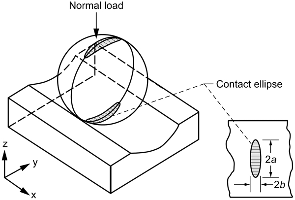
Schematic of contact profile of ball on raceway; semiwidths of a major and b minor axes of Hertzian contact area
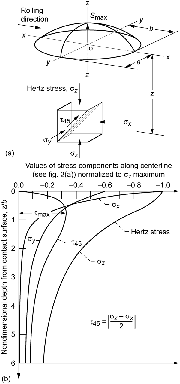
Subsurface stress field under point contact
Three shearing stresses can be applied to bearing life analysis: the orthogonal shearing stress τo, the octahedral shearing stress τoct, and the maximum shearing stress τmax. The von Mises stress which is not a shearing stress has been inappropriately used by some investigators as a substitute for the octahedral shearing stress τoct. All of these shearing stresses are a function of the maximum Hertz stress where

For the analysis reported herein, only the maximum shearing stress is considered. The maximum shearing stress is one-half the maximum difference between the principal stresses


Generally, the spall begins in the region of maximum shearing stresses and propagates into a crack network. Most bearings, however, fail for other reasons. Failures other than those caused by classical rolling-element fatigue are considered avoidable if the bearing is properly designed, handled, installed, and lubricated and is not overloaded.7
Rolling-element fatigue is extremely variable but is statistically predictable depending on the steel type, steel processing, heat treatment, bearing manufacturing and type, and operating conditions. Sadeghi et al.8 provide an excellent review of this failure mode.
Alley and Neu9 provide a recent attempt at modelling rolling-element fatigue. With improved bearing manufacturing and steel processing together with lubrication technology, the potential improvements in bearing life can as much as 80 times that attainable in the late 1950s or as much as 400 times that attainable in 1940.3
Based on the 1947 work by Lundberg and Palmgren10 who use the orthogonal shearing stress τo for their analysis, the life of a ball or roller bearing based on rolling-element fatigue can be expressed in its most simplistic form as follows

The L10 life, in millions of inner race revolutions, is the theoretical life that 90% of a bearing population should equal or exceed without failure at their operating load P. C is defined as the theoretical load that a bearing can carry for a life of 1 million inner-race revolutions with a 90% probability of survival. The load–life exponent is p. LF is a life factor dependent on the bearing steel and its processing.11
Lundberg and Palmgren10 derive the load–life exponent p to be 3 for ball bearings and 4 for roller bearings. However, in their 1952 paper,12 Lundberg and Palmgren modified their value of the load–life exponent p for roller bearings from 4 to 10/3. Their rationale for doing so was that various roller bearing types had one contact that is line contact and other that is point contact. They state ‘… as a rule the contacts between the roller and the raceways transforms from a point to a line for some certain load so that the life exponent varies from 3 to 4 for differing loading intervals within the same bearing.’ The ANSI/ABMA13 and ISO14 Standards incorporate p = 10/3 for roller bearings. Computer codes for rolling-element bearings incorporate p = 4 for roller bearings and p = 3 for ball bearings.11
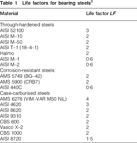
Bearing lives determined by using equation (1) with the values of C given in bearing manufacturers’ catalogues are based on the ‘first evidence of fatigue.’ This can be a tiny spall that may not significantly impair the function of the bearing. Thus, the actual useful life can be much longer. Society of Tribologists and Lubrication Engineers life factors LF for various bearing steels are given in Table 1.3 It can be reasonably assumed that these life factors are benchmarked to air melt AISI 52100 steel at a maximum Hertz (contact) stress of 1·723 GPa (250 ksi). Table 2 provides the designation and chemistry of these and other representative bearing steels.15
Life factors for bearing steels3
Representative bearing and gear steels15
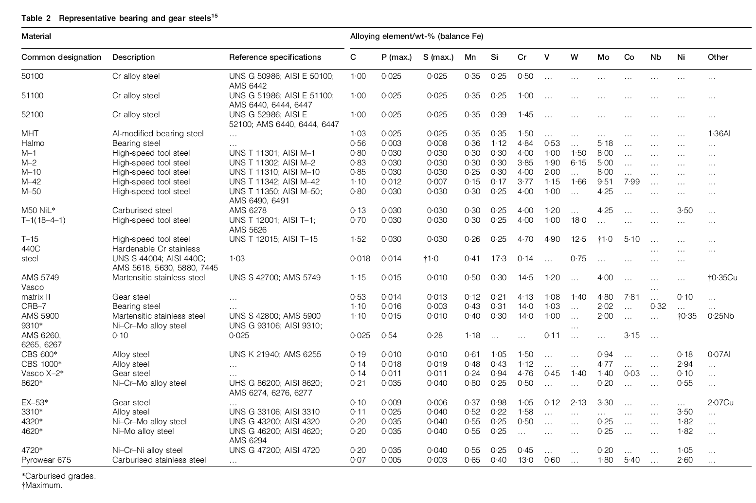
*Carburised grades.
†Maximum.
Steel chemistry
Through-hardened steels
In the 1950s thru the 1960s the bearing industry assumed that materials with higher alloy content would have better hardness retention at elevated temperatures. It was reasoned that this would also result in higher ambient-temperature hardness as well as longer bearing life. Based on this assumption steel companies and research laboratories within the United States began to develop bearing steels with higher alloy content.
It is necessary to compare these steel and processing variables in rolling-element fatigue tests and/or actual bearing tests. Standard mechanical tests, such as tension and compression tests or rotating-beam tests, could not be correlated with rolling-element fatigue results.16 Accordingly, a series of studies to verify the effect of increased alloying elements on rolling-element fatigue life was undertaken by the author and his colleagues at the NASA Lewis Research Center (now NASA Glenn Research Center), Cleveland, OH, USA. 17 17,18
Figure 3a summarises the results of rolling-element fatigue tests conducted in the NASA five-ball fatigue tester.17 Previous studies by others did not maintain the close control of operating and processing variables, such as material hardness, melting technique, and lubricant type and batch, required for a completely unbiased material comparison.18 These tests compromised three groups each of eight through-hardened bearing steels. There were a total of 720 tests. All of the specimens for the specified steel came from the same heat of material and were manufactured and heat treated to the same hardness at the same time. All other variable were as carefully controlled. Contrary to expectation, rolling-element fatigue life decreases with increasing total content of alloying element in the steel. When present in high percentages these alloying elements appear to significantly decrease rolling element fatigue life.
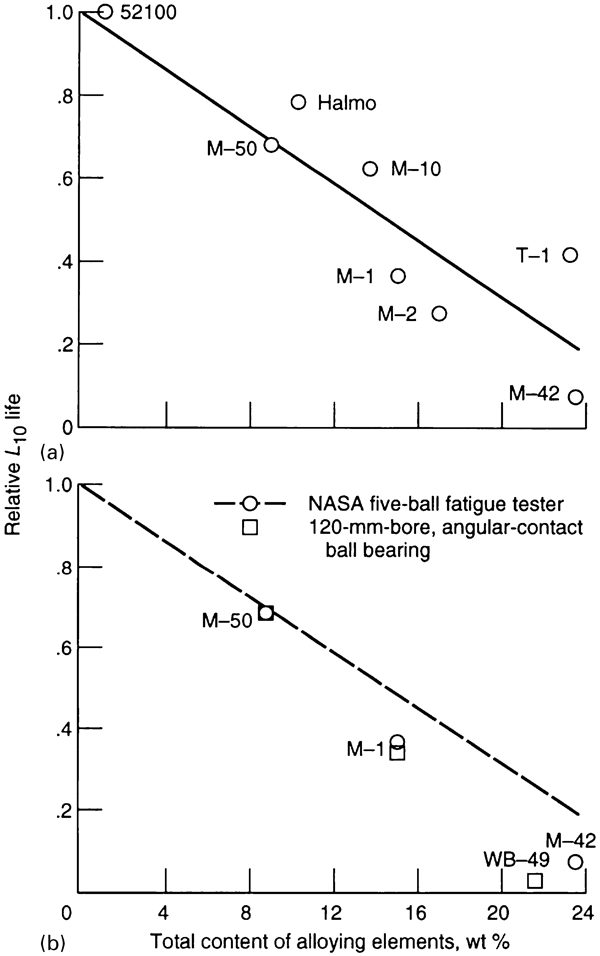
Rolling-element fatigue life as function of total content of alloying elements tungsten, chromium, vanadium, molybdenum and cobalt17
Additional work, shown in Fig. 3b, was performed with 120-mm-bore, angular-contact ball bearings made from VAR AISI M–I, AISI M–42, AISI M–50 and WB–49 steels to verify the results in the NASA five-ball fatigue tester. 17 17,19 Bearings were tested at an outer-race temperature of 316°C (600°F). These four test series comprised a total of 120 bearings, 30 for each steel. The magnitudes of the differences seen in these bearing tests at 316°C (600°F) correlate well with the results of five-ball fatigue tests that are also shown in Fig. 3a. Using the AISI M–50 L10 life as a comparison, the AISI M–1 data from the five-ball fatigue tests and from the bearing tests agree remarkably well. WB–49 in the bearing tests and AISI M–42 in the five-ball fatigue tests, both of which alloys contain relatively high percentages of cobalt and have similar microstructures, show reasonably good agreement.20
These results completely changed previously held assumptions regarding the effect of bearing steel alloying elements on rolling-element fatigue life. As a result, by the mid 1980s AISI M-50 steel became the steel of choice for most high-temperature bearing applications over 149°C (300°F). For bearing temperatures less than 149°C (300°F), AISI 52100 steel with the lowest alloying content has a longer fatigue life and is probably the most widely used bearing steel throughout the world. These steels are usually heat treated to Rockwell C hardness at room temperature of not less than 60. At operating temperature, it is a general requirement that the operating hot hardness be greater than Rockwell C 58.
Carburising grade steels
Bearings are required to tolerate substantial damage progression without catastrophic fracture during the interval between the onset of a problem and when routine maintenance identifies the need for repair. 21 21,22 Material toughness provides this capability. Fracture toughness is the material property that defines the stress required to initiate rapid fracture in the presence of a local defect (e.g. a fatigue spall). Initial defect size substantially affects fracture characteristics but is beyond the control of the designer. Tensile stresses, either application induced or residual, are necessary for rapid fracture to occur. These are somewhat controllable by the designer, but advanced applications will require tolerance to increased stress.3
Through-hardened materials, heat treated to Rockwell C 60 hardness, as is typical with bearing components, have limited fracture toughness. The KIC is usually less than 24 MPa m1/2 (22 ksi in.1/2), depending upon heat treatment.23 Materials with fracture toughness this low have limited bulk tensile stress capability if rapid fracture is to be avoided. A conservatively safe limit is 172·4 MPa (25 ksi). Applications requiring higher toughness will have to be made from a carburising-grade steel.3
Carburising-grade steels have reduced carbon content so that heat treatment normally results in moderate hardness and high toughness. High surface hardness, which is required for rolling-element bearing performance, is achieved by diffusing carbon into the surface, a process called carburising, prior to heat treatment. Locally the steel is then a high-carbon alloy and is heat treatable to full hardness. The resulting structure has a surface layer with mechanical properties that are equivalent to those of traditional through-hardened bearing steels and a core that remains at low hardness, with corresponding high ductility and high fracture toughness. Surface-initiated defects (e.g. a spall) propagate cracks into the tough core before they reach critical size. The tough core prevents rapid and catastrophic fracture.3
Fracture toughness of a material is inversely proportional to its carbon content and hardness. The carbon content also determines hardness. Fracture toughness can be improved without affecting hardness by adding nickel. When present in high-chromium, low-carbon steels, nickel causes the steel to become fully austenitic above 875°C (1605°F) where the steel is heat treated or carburised. Adding nickel also influences carbide size and distribution within the steel, which affects fatigue life. Recognising this, Bamberger24 modified the chemistry of AISI M–50 steel by decreasing the amount of carbon and increasing the amount of nickel. He called this modified AISI M-50 steel M50 NiL (the ‘Ni’ referring to increased nickel and the ‘L’ to low carbon). The steel is also designated as Aerospace Material Specification (AMS) 6268.
M50 NiL, which is case carburised, has a core with a higher fracture toughness KIC (over 60 MPa-m1/2; 50 ksi-in.1/2) than through hardened AISI M-50 (29 MPa-m1/2; 20 ksi-in.1/2). The M50 NiL core hardness is Rockwell C43 to 45. M50 NiL has finer carbides (compounds of carbon and various alloying elements) dispersed more evenly within its microstructure than standard AISI M–50. Compressive residual stresses in excess of 210 MPa (30 ksi) are induced in the zone of maximum resolved shear stresses during carburisation of M50 NiL. These residual stresses combined with the fine carbide structure will increase its rolling-element fatigue life over that of conventional AISI M–50.25
Many carburised gear steels are also used as bearing steels. These carburised steels are primarily used for tapered roller bearings or other bearings such as cylindrical roller bearings where tight interference fits are required between the bearing bore and shaft. A tight interference fit will induce large tensile (hoop) stresses in the bearing inner ring that can cause catastrophic fracture failure of the ring and the bearing. As with AISI 52100 steel, for temperatures less than 149°C (300°F), AISI 9310 and AISI 8620 are usually the materials of choice. However, for bearing operating temperatures greater than 149°C (300°F), M50 NiL is the steel of choice.
Corrosion-resistant steels
Although not normally a functional requirement, corrosion resistance is highly desirable because of its potentially large effect on life-cycle cost. Alloy steels with high chromium content, greater than 12%, are considered corrosion resistant. However, although the chromium forms a passive chromium oxide layer at the surface that provides substantial protection, it is not inert and these alloys will corrode in hostile environments.3
Available corrosion-resistant bearing alloys include AISI 440C and the high-temperature variations such as AISI 440C Mod, Aerospace Material Specification (AMS) 5749 (VIM–VAR BG-42), AMS 5900 (VIM–VAR CRB7) and Pyrowear 675. AISI 440C is widely used in instrument bearings and in bearings for food-processing equipment. In addition, AISI 440C is the traditional alloy chosen for use in cryogenic rocket engine turbopumps such as those in the NASA Space Shuttle. AMS 5749 (VIM–VAR BG-42), AMS 5900 (VIM–VAR CRB7) and Pyrowear 675 are more recent developments.3 For temperatures less than 149°C (300°F), AISI 440C is the corrosion resistant steel of choice. For temperatures greater than 149°C (300°F), AMS 5749(BG-42) is the steel of choice.
Steel processing
In the early years of the bearing industry acid- and base-refractory, air-melting methods were used to process steel Major advances in steel producing have occurred beginning in the 1950s by the introduction of vacuum-melting procedures. Vacuum processing reduces or eliminates the amount of nonmetallic inclusions, entrapped gases, and trace elements in structural alloys, resulting in substantially cleaner material. The two primary methods of vacuum processing are vacuum induction melting (VIM) and consumable-electrode vacuum melting (CEVM) also called vacuum arc remelting (VAR). In the early 1970s, these two methods were combined, whereby the vacuum induction primary melt is vacuum arc remelted. This method, called VIM–VAR, produces much cleaner steel than either VIM or CEVM individually.26 These results are shown in Fig. 4.
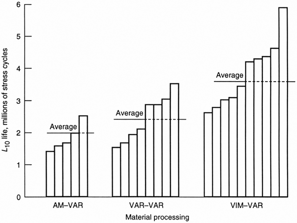
Rolling-element fatigue life of AISI M–50 steel in rolling-contact fatigue tester as function of steel processing. Specimen diameter, 9·525 mm (3/8 in.); maximum Hertz stress, 4·8 GPa (700 ksi); speed, 12 500 rev min−1 (Ref. 26)
Although CEVM and VIM–VAR are the primary methods used today to produce materials such as AISI M–50, other vacuum processing methods have been developed, primarily aimed at improving AISI 52100. The effect of melting practice on rolling-element fatigue life is shown by the Society of Tribologists and Lubrication Engineers life factors (LF) in Table 3.3 The product of the life factors for bearing steel from Table 1 and melting practice from Table 3 is used as a single life factor LF in equation (1) to determine the bearing L10 life.
Life factors for melting practice3
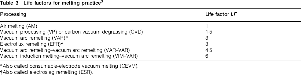
*Also called consumable-electrode vacuum melting (CEVM).
†Also called electroslag remelting (ESR).
Vacuum processing of bearing steel increases bearing life by eliminating hard oxide inclusions that act as stress raisers to initiate incipient failure. This results in an unforeseen secondary benefit. The fatigue life of the bearing steel becomes more sensitive to a reduction in stress. That is, as contact load or (Hertz) stress is decreased, bearing fatigue life is increased at a faster rate than with the air melted bearing steels.
As previously discussed the load–life exponent p in equation (1) is 3 for ball bearings and 4 for roller bearings based on pre-1940 air melt AISI 52100 steel. However, a re-evaluation of the load–life relation27–29 based on a summary of published data by Parker and Zaretsky30 suggests that for post-1960 vacuum processed bearing steels, the load–life exponent p equals 4 and 5 for ball and roller bearings, respectively. This accounts for another significant improvement in rolling bearing life and reliability.
Heat treatment
Steel hardness
Hardness is an influential heat-treatment-induced variable. For most rolling bearing applications it is required that the Rockwell C hardness at operating temperature be 58 or higher. In general, the higher the hardness of the bearing steel at operating temperature, the longer the life. A relationship that approximates the effect of bearing material hardness on fatigue life has been developed
20
20,31

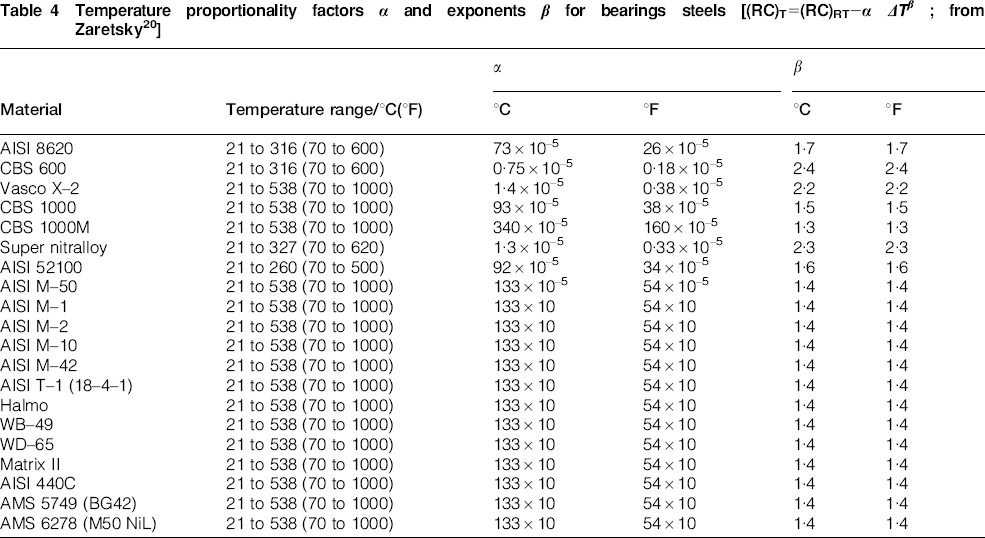
As was discussed for through hardened steels, the bearing industry also assumed that materials with higher alloy content would have better hardness retention at elevated temperatures. A study to verify this assumption was undertaken at NASA Lewis Research Center.32–34 Short-term, hot-hardness measurements were made for groups of through-hardened specimens of AISI 52100, M–1, M–50, 440C, Halmo, WB–49, WD65 and Matrix II. Measurements were also made of specimens of Super Nitralloy (5Ni–2A1) and case-carburised AISI 8620, CBS 600, CBS 1000 and Vasco X–2. The results for the AISI 52100 and the other through-hardened steels were normalised and are shown in Fig. 5. These normalised data show that regardless of the initial hardness, the hot hardness of individual materials shows the same functional dependence. These results completely changed previously held assumptions.20 The data can be represented by a straight line having the form

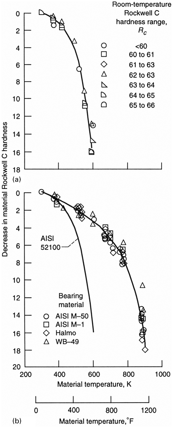
Summary of short-term, hot-hardness, through-hardened bearing steel data20
Temperature proportionality factors α and exponents β for bearings steels [(RC)T = (RC)RT−α ΔTβ; from Zaretsky20]
To determine hardness effects at the bearing operating temperature, equations (2) and (3) can be combined to obtain a life factor as follows

Compressive residual stresses
From the late 1920s through to the 1960s, Almen35 and his colleagues36–38 at the General Motors Research Laboratories pioneered the study of residual stresses in rotating steel components that included rolling-element bearings. These residual stresses can either be tensile or compressive. They can be induced by producing microscopic and macroscopic deformations and by transformations in the microstructure of the steel. Residual stresses can also be induced by heat treating, rolling, shot peening, diamond burnishing, and severe grinding. Each of these methods (except heat treating) is a separate mechanical process that is performed after heat treating.15
They found that compressive residual stresses induced beneath the surface of ball bearing race grooves increase rolling-element fatigue life. According to Gentile and Martin37 ball bearing lives were doubled when metallurgical induced (‘prenitrided’) compressive residual stresses were present in the inner races. Scott et al.38 found that compressive residual stresses induced by unidentified ‘mechanical processing’ extend the fatigue life of ball bearings.15
Figure 6 shows representative residual stresses as a function of depth below the surface for three heat-treated bearing steels. In general, most, if not all, carburised bearing steels have induced compressive residual stresses represented by those shown for AISI 9310 steel in Fig. 6. These stresses are induced by the carburisation process.
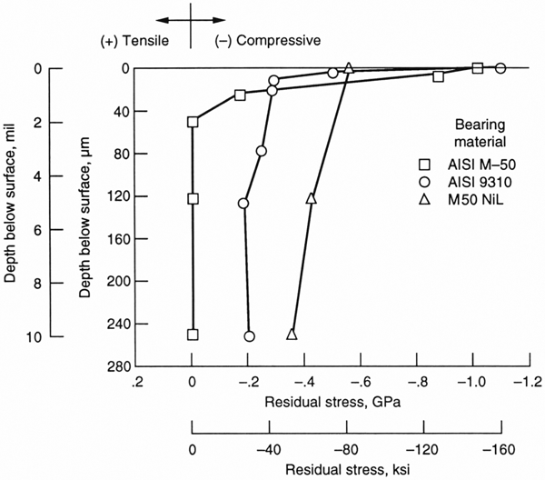
Representative principal residual stress as function of depth below surface for heat treated AISI M–50, AISI 9310, and M50 NiL (AMS 6278)3
In 1965, E. V. Zaretsky
15
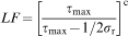
15,39 and his colleagues at the NASA Lewis (now Glenn) Research Center published an equation relating rolling-element fatigue life to these compressive residual stresses. The maximum shearing stress τmax for a given contact stress is decreased by the presence of a compressive residual stress σr. This results in the following life factor due to residual stresses alone
For light to moderately loaded bearings a typical value of τmax is 414 MPa (60 ksi). For heavily loaded bearings a typical value of τmax is 724 MPa (105 ksi). From Fig. 6, assume AISI 9310 as the bearing steel. The compressive residual stress σr is 200 MPa (29 ksi). From equation (8), for a lightly loaded bearing, LF≈12. For a heavily loaded bearing, LF≈3·8. These life factors can be applied in equation (1) together with the other life factors discussed. However, when bearing life results are analysed independent of these residual stresses, the load–life exponent p appears to increase from their accepted values.40
Investigators have misinterpreted these results caused by the presence of residual stresses as a ‘fatigue limit.’41 They have incorporated them into bearing life predictions and in some cases bearing manufacturer catalogues.42 The concept of a fatigue limit has also been incorporated into an ISO standard43 for bearing life prediction for AISI 52100 steel where there are no residual stresses in the as heat treated steel.42 This can result in bearing life over prediction and/or under sizing a bearing for a particular application. 41 41,42
There are two problems associated with the use of a fatigue limit for bearing steels. The first problem is as discussed above, the form of the equation as expressed in the ISO standard43 may not reflect a fatigue limit but the presence of a compressive residual stress. The second problem is that there are no data in the open literature that would justify the use of a fatigue limit for through hardened bearing steels such as AISI 52100 and AISI M-50. 41 41,42
In 2007, Sakai44 and his coworkers45 presented stress life rotating bending fatigue data from six different laboratories in Japan for AISI 52100 steel. He also presented stress-life fatigue data for axial loading. The resultant lives were in excess of one billion (>109) stress cycles at a maximum shearing stress τmax as low as 350 MPa (51 ksi) without an apparent fatigue limit.
In 2008, Tosha et al.46 of Meiji University in Japan reported rotating bending stress-life fatigue tests for through hardened bearing steels having Rockwell C hardness above 58. The results of these tests at maximum shearing stresses τmax as low as 480 MPa (70 ksi) produced fatigue lives in excess of 100 million (>108) stress cycles without the manifestation of a fatigue limit.
In 2009, in order to verify the results of Sakai44 and his coworkers45 and Tosha et al.,46 Shimizu et al.47 also of Meiji University, published the results from six groups of AISI 52100 bearing steel specimens using four-alternating torsion fatigue tests rigs to determine whether a fatigue limit exists or not and to compare the resultant shear stress–life relation with that used for rolling-element bearing life predition.42 The results of these tests at maximum shearing stresses τmax as low as 500 MPa (76 ksi) produced fatigue lives in excess of 10 million (>107) stress cycles without a fatigue limit. Shimizu et al.47 reported that the resultant fatigue life was inversely related to the shearing stress to the 10·34 power.42
Retained austenite
In the early 1960s, a major US aircraft engine company had to discard unused rolling-element bearings made from AISI M-50 because their bore diameter had increased from that specified for the engine shaft diameter (in a personal communication with E. N. Bamberger, General Electric Company, February 1963). This expansion in bore size was attributed to the presence of large amounts of retained austenite in the microstructure of the steel. The retained austenite transformed to martensite and bainite on the shelf at room temperature. As a result, for most critical aerospace applications, the retained austenite is limited to 2 to 5%. However, for noncritical applications, higher amounts of retained austenite are allowed or may, in some instances, be uncontrolled. Experience has suggested that lower values of retained austenite are preferable for reliable bearing operation.15
L. R. Waldmiller of Frost, Inc. (in a personal communication, December 1994) described unrun, carburised, 12·7-mm (0·5-in.) diameter AISI 1022 balls having 40 to 50% retained austenite. The balls lost a portion of the case material while at room temperature due to transformation of the retained austenite. The lost material had the appearance of a ‘skullcap’ and the phenomenon was referred to as ‘capping’. He reported that the phenomenon also occurs during bearing operation. The same material with a lower amount of retained austenite did not experience capping.15
In general, for a given through-hardened material the amount of retained austenite increases with increasing material hardness. Experience has also shown that test rollers made from AISI 52100 of Rockwell C hardnesses greater than 63 will have sufficient austenite-to-martensite transformation during rolling contact to alter the surface waviness and cause early surface spalling.15
Johnston et al.48 studied the effect of the decomposition of retained austenite and the inducement of compressive residual stress as a result of bearing operation. What is unique for their data is that the magnitudes of the compressive residual stresses are directly proportional to the decomposition of retained austenite.15
Changes in microstructure (phase transformations) have been reported to occur in the same areas as the maximum induced residual stress. 36 36,49 Under some conditions of extremely high contact stresses, non-microstructural alteration was apparent after significant residual stresses had been induced in a few cycles.49 Muro and Tsushima50 proposed that the induced residual stresses and the microstructural alterations are independent phenomena.15
Research performed by Zhu et al.51 in 1985 on carburised rollers suggested that the structural change in the zone of maximum resolved shearing stresses observed by Jones52 in 1947 and later by Carter53 in 1960 as well as others is a manifestation of retained austenite transforming to martensite under cyclic Hertzian stress conditions. A combination of thermal and strain energy and time is believed to cause this change.15
Grain size
It is generally accepted in the bearing industry that prior austenite grain size should be ASTM number 8 or finer and that individual grains should not exceed ASTM number 5.54 The higher the ASTM number, the finer the grain size. The 1960 work of Baughman55 suggested that rolling-element fatigue life increases with finer grain sizes.20 A recent analysis of grain size and orientation on rolling-element fatigue life was performed by Weinzapfel et al.56
Carbides
Residual carbides are those carbides that do not go completely into solution during austenitising and are a function of the alloying elements and raw material processing. In contrast, hardening carbides precipitate upon aging at the tempering temperature. The carbides referred to in the following paragraphs are the residual carbides.
Carbide composition has been found to vary among steel producers. Heat treating steel ingots creates large, extremely hard MC carbides, considered to be essentially a vanadium carbide, which can act as asperities in the bearing surface.57 J. E. Bridge et al.58 identified the primary carbides in AISI M–50 as MC and M2C. Pearson and Dickinson57 found that the M2C carbides contain a high percentage of molybdenum and that in a bearing ball under thin film elastohydrodynamic lubrication conditions they can cause distress or peeling of the bearing race surfaces. The carbide ‘stick out’ has been attributed in whole or in part to an excessive rate of grinding in the manufacture of bearing balls made from AISI M-50 steel.
Parker et al. 17 59 17,59,60 have shown an interrelation among steel alloy content, median residual carbide size, number of residual carbide particles per unit area, percentage of residual carbide area in through hardened bearing steels, and rolling-element fatigue life. As the percentage of alloying elements increase in a steel the number and size of the carbides increase. 61 61,62 Subsequent research by Parker and Bamberger63 for AMS 5749 steel further substantiated the negative effect of large carbide size and banded carbide distribution on rolling-element fatigue life.
Pearson and Dickinson57 verified the observations of Butterfield and McNelley,64 who reported voids of the order of 1 μm (40 μin.) adjacent to carbides of AISIM–50 steel. This work64 suggested that these voids form during bearing operation at the site of the carbide tip and can act as a nucleus for crack initiation in the subsurface zone of maximum shear stresses. The large carbides act as stress raisers to initiate an incipient crack that results in a rolling-element fatigue spall. The effect of carbides on rolling-element fatigue life is reflected in the life factors of Table 1.15
In general, case carburised bearing steels, with the exception of M50 NiL, have a more course and larger carbide structure when compared to through hardened bearing steels such as AISI 52100 or AISI M-50. However, this disadvantage is more than offset by the compressive residual stresses induced into the case by the carburisation process.
Summary
In order to assure long rolling-element bearing life and reliability for commercial, industrial and aerospace applications, materials, lubricants and design variables must be carefully considered and specified. The catalyst to quantum advances in high-performance rolling-element bearing steels was the advent of the aircraft gas turbine engine. The reliability of these bearings became a major consideration because of system and mission complexities and because of the high costs involved. With improved bearing manufacturing and steel processing together with lubrication technology, the potential improvements in bearing life can as much as 80 times that attainable in the late 1950s or as much as 400 times that attainable in 1940. The following summarises the chemical, metallurgical and physical aspects of bearing steels and their effect on rolling bearing life and reliability.
For temperatures less than 149°C (300°F) the bearing steels of choice are: through-hardened, AISI 52100; case-carburised, AISI 8620 and AISI 9310; and corrosion-resistant, AISI 440C. For temperatures greater than 149°C (300°F) the bearing steels of choice are: through-hardened, AISI M-50; case-carburised, M50 Nil; and corrosion-resistant, BG-42.
Vacuum processing of bearing steel reduces or eliminates the amount of non-metallic inclusions, entrapped gases, and trace elements in structural alloys, resulting in substantially cleaner material and significantly longer bearing life.
For a post-1960 vacuum processed bearing steels such as AISI 52100 and AISI M-50, the values for the load–life exponent p, where life is inversely proportional to load to the exponent p, increased from 3 and 4 for ball and roller bearings, respectively, to 4 and 5.
Minimum hardness for bearing steel at operating temperature should not be less than Rockwell C 58. Bearing life increases with increasing steel hardness at operating temperature. A 3 point increase in hardness can result in a 35% increase in bearing life. For M-Series bearing steels, the change in hardness with temperature is independent of alloy content.
Bearing steels with high chromium content, greater than 12%, such as AISI 440C are considered corrosion resistant. Although the chromium forms a passive chromium oxide layer at the surface that provides substantial protection, it is not inert and these alloys will corrode in hostile environments.
Compressive residual stresses induced or present from heat treatment beneath the surface of bearing steel components increase rolling-element fatigue life and can alter the Hertz stress–life relation. A compressive residual stress of 200 MPa (29 ksi) can increase bearing life for a lightly loaded bearing by a life factor, LF≈12. For a heavily loaded bearing, LF≈3·8.
For most critical aerospace applications, retained austenite is limited to 2 to 5%. However, for non-critical applications, higher amounts of retained austenite are allowed or may, in some instances, be uncontrolled. Experience has suggested that lower values of retained austenite are preferable for reliable bearing operation.
Rolling-element fatigue life increases with finer grain sizes. Prior austenite grain size should be ASTM number 8 or finer and that individual grains should not exceed ASTM number 5. The higher the ASTM number, the smaller the grain size.
There is an interrelation among steel alloy content, median residual carbide size, number of residual carbide particles per unit area, percentage of residual carbide area, and rolling-element fatigue life. The large carbides act as stress raisers to initiate an incipient crack that results in a rolling-element fatigue spall. As the percentage of alloying elements increase in through hardened bearing steel, the number and size of the carbides increase.
Case carburised bearing steels, with the exception of M50 NiL, have a more course and larger carbide structure when compared to through hardened bearing steels such as AISI 52100 or AISI M-50. However, this disadvantage is more than offset by the compressive residual stresses induced into the case by the carburisation process.
Footnotes
This paper is part of a special issue on ‘Bearing steels’