
Abstract
A coupled thermomechanical three-dimensional finite element model was developed for friction stir welding in the ABAQUS environment using Johnson–Cook material law and Johnson–Cook failure model. The temperature evolution during the plunge, dwell and moving stages of a friction stir welded 7050 aluminium alloy and the effect of heat conduction by the back plate were investigated. Results show that the temperature almost symmetrically distributes across the plate cross-section, and the temperature contour in the weld nugget zone presents a V type shape after the plunge stage. In the dwell stage, the frictional heat conducts around to preheat the plate. While in the moving stage, the heat gradually accumulates until a quasi-stable temperature field is formed. Moreover, it is shown that the heat conduction through the back plate has a significant effect on the temperature field. With the increasing heat convective coefficient of the back plate, the temperature field remarkably shrinks.
Introduction
Friction stir welding (FSW) is an innovative solid state joining process that has been paid increasing attention due to its great potential in welding light alloys. Research on the FSW over the past decade has mainly focused on the microstructures and properties of joints and the exploiture of friction tools and equipments. In recent years, significant progress has been made in the understanding of the mechanism and physical process involved in the FSW process, and one of the most efficient research methods is numerical modelling.1
Ulysse2 simulated the FSW process using a three-dimensional (3D) finite element (FE) model. Pin rotation was simulated by prescribing a constant tangential velocity on the pin surface. Khandkar et al.3 presented an axisymmetric FE thermal model of the FSW based on the tool torque, which fundamentally differs from previous frictional heating models. Chen and Kovacevic4 established a 3D FE analysis model to study the thermal history and thermomechanical process. The moving heat source of the shoulder and probe was represented as the moving heat generation of the element nodes in each computation time step, where a constant value was used to approximate the coupled thermal and plastic effects during FSW. Although these models could provide good thermal information, they have low flexibility because the tool design and transient stages of the FSW were not taken into account.
Schmidt et al.5 developed a fully coupled thermomechanical 3D FE model that begins the simulation from the point where the shoulder had already contacted with the plate. Soundararajan et al.6 established a 3D thermomechanical model with adaptive boundary conditions to predict transient temperature field and reactive stresses. Zhang and Zhang7 developed a fully coupled thermomechanical model to predict the effect of the axial pressure. They8 also studied the effect of transverse speed on the calculation outputs of FSW.
The above FE models simulated either the moving (or welding) stage or the dwell and moving stages, but they could not treat the entire FSW process, including the plunge stage.9 Very few papers10,11 have concerned the plunge stage or the ‘initial stage’ composed of the plunge and dwell stages. The reason is the excessive mesh distortion of the FE model, which can lead to the abnormally premature termination of the programme. However, research on these stages of FSW is extremely critical since the initial thermomechanical conditions are very important. Mandal et al.10 have developed a 3D thermomechanical model to study the plunge stage with the software ABAQUS/Explicit. In our previous study,11 a model with a finer mesh was established to study the effects of the rotation speed and the inserting time on the temperature field during the plunge stage of FSW. The failure of elements during simulation was referred to as an important and effective technique to cope with the excessive distortion problem. Therefore, in the present study, a 3D thermomechanical FE model using the Johnson–Cook failure model was newly set up to investigate the temperature history of the entire FSW process.
Numerical method
Computational model
The present model is composed of a deformable plate and a rigid tool, as shown in Fig. 1. The tool shoulder has typically a concave cone instead of a plane to trap the material expelled from the stir zone. The dimensions of the tool are illustrated in Fig. 1a. The plate was meshed using eight-node coupled temperature displacement and brick elements (C3D8RT), and the mesh was gradually changed in order to make a compromise between computation efficiency and accuracy. The final mesh is shown in Fig. 1b.
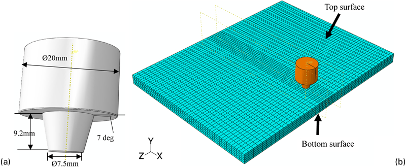
a tool design and b meshing of plate in simulations
Material model
The Johnson–Cook material model was used to describe the flow stress σ as a function of strain hardening, strain rate hardening and temperature softening as follows
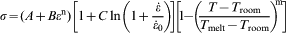
 are the strain and strain rates respectively,
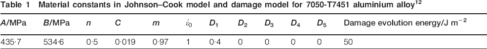
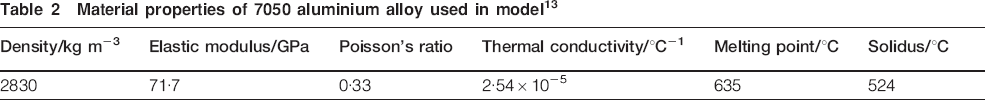
  is the reference strain rate, Troom is the reference temperature and Tmelt is the melting point. A, B, n, C and m are the constants dependent on the material. These constants for 7050 alloy are given in Table 1. The other thermal and mechanical properties of 7050 alloy used in this model are listed in Table 2.
Material constants in Johnson–Cook model and damage model for 7050-T7451 aluminium alloy12

Material properties of 7050 aluminium alloy used in model13
Material failure model
To cope with the abnormal element distortion, the Johnson–Cook damage model was introduced in the simulation. The fracture in this model is derived from the cumulative damage law as follows


Boundary conditions
In the present model for FSW, the main heat source is considered to be the frictional heat between the rotation tool and the plate. However, the friction coefficient is rather difficult to evaluate due to its dependence on the temperature, pressure and relative slip velocity. Chao and Qi16 thought that the friction coefficient varied in a range of 0·4–0·5. As the interfacial temperature between the tool and the plate increased, the friction coefficient would decrease from 0·5 to 0·4. Therefore, in the present model, the friction coefficient was assumed to be 0·5 for the plunge stage and 0·4 for the subsequent dwell and moving stages, which was implemented using the available surface to surface contact (Explicit) formulation in ABAQUS. In addition, an empirical assumption that 90 plastic work and 100 friction work were dissipated as heat was made. Considering the complicated heat conduction between the tool and the plate, the total friction heat was distributed to each part through the following equation17

A convection coefficient of 30 W m−2 K−1 on the plate top surface and sides was used to simulate the heat dissipation to the atmosphere. However, the heat transfer through the back plate was more complicated because of the uncertainty associated with the contact gap conductance.3 Therefore, a large overall heat transfer coefficient, subsequently referred to as the bottom convective coefficient (BCC), was used to simulate the heat loss through the bottom surface of the plate. Six different BCCs were used, i.e. 0 (adiabatic condition), 500, 1000, 1500, 2000 and 3000 W m−2 K−1, to study its effect on the temperature evolution of the plate. The BCC of 500 W m−2 K−1 was first employed to show the representative temperature evolution during FSW 7050 alloy based on the result that the convective coefficient of 500 W m−2 K−1 correlated well with the experimental results reported by Chen and Kovacevic.4 In the simulation, both the tool rotation speed (300 rev min−1) and the welding speed (2·5 mm s−1) are enforced on the tool reference point, while the plate is fixed at the bottom and sides. The plunge, dwell and moving times in the simulations are 10, 5 and 30 s respectively.
Results and discussion
Representative temperature evolution during FSW 7050
The temperature evolution during the plunge stage (0–10 s) is shown in Fig. 2. First, the rotating tool began to penetrate into the plate, causing the material to be squeezed out, and a semicircle temperature distribution in the plate was observed, as shown in Fig. 2a. As the tool continued to march, the contact area between the tool and the plate increased; correspondingly, more heat was produced and conducted into the plate, causing the dissipation of heat to the surrounding to form a symmetrical temperature distribution across the plate cross-section. At the same time, the elements under the tool were deleted (Fig. 2b and c) as their thermomechanical conditions arrived at the threshold according to the Johnson–Cook damage model. Until the tool contacted with the plate, the plunge stage finished. It is worth noticing that the temperature increased significantly to a maximum value due to the maximum contact surface between the tool and the plate at the moment the shoulder contacted the plate. In addition, the temperature contour in the weld nugget zone presented a V type shape (Fig. 2d), and the higher temperature zone moved from the region beneath the tool pin (Fig. 2a) to the corner area formed by the shoulder and welded plate (Fig. 2d), where the shoulder and the pin contributed jointly to the highest heat flux. It should be pointed out that the deletion of high temperature elements from the calculation will cause some heat loss. However, the predicted temperatures in other regions are comparable with the experimental results.11 How this heat loss influences the temperature distribution, especially in the moving stage, is not the emphasis of the present study and will be studied in the future.
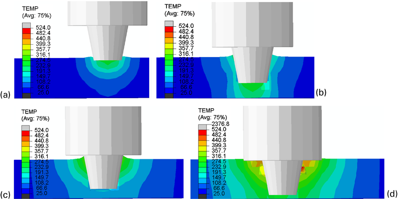
Temperature contours in cross-section at different times of plunge stage
The temperature evolution during the dwell stage (continuously counted as 10–15 s) is shown in Fig. 3. Based on the previous thermomechanical conditions of the plunge stage, in this process, the heat had been conducted around to heat other regions. However, the high temperature zone shrank due to the lowered heat input from the contact face caused by element deletion. Actually, it was not the real case. In the actual dwell stage of FSW, the tool keeps rotating without moving forward for further softening the material under the tool and producing more heat for preheating the material ahead. Thus, a higher friction coefficient was used to compensate the heat loss compared with 0·3 adopted by the previous thermal model.5 It is the main defect when using the failure model, but it can be improved through the refinement of meshing size and the control of meshing zones.
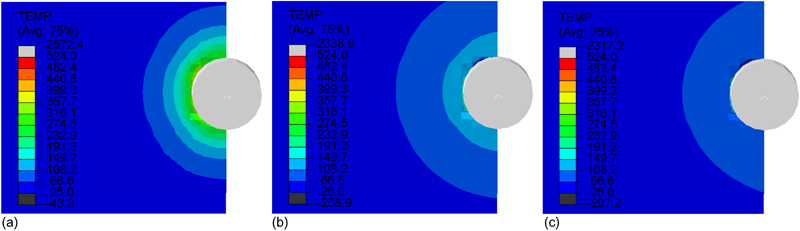
Temperature contours on top surface of welded plate at different times of dwell stage
The temperature evolution during the moving stage (continuously counted as 15–45 s) is shown in Fig. 4. As the tool continuously marched, the temperature at the contact zone again started to increase obviously (Fig. 4a), which is because the tool began to contact with the elements ahead. It was found that the temperature distribution around the tool tended to be a quasi-stable state, as observed in Fig. 4b–f. In addition, the temperature contours of the plate in front of the tool were similar (Fig. 4e and f), which may indicate that the heat generation and dissipation kept a balance at the quasi-stable stage. The maximum quasi-stable temperature was in the range between 460 and 500°C, which is accordant with the calculated results by Schmidt et al.5 Moreover, it was surprising that the temperature distribution on the top surface of the plate was not axisymmetric anymore (Fig. 4f), where the high temperature zone at the retreating side (see Fig. 4a) was a little larger than that at the advancing side. It could be because that the retreating side accumulated more heat than the advancing side. These phenomena were also accordant with the observed one of a practical FSW process. However, this characteristic cannot be predicted using the moving heat source technique in the previous simulations.
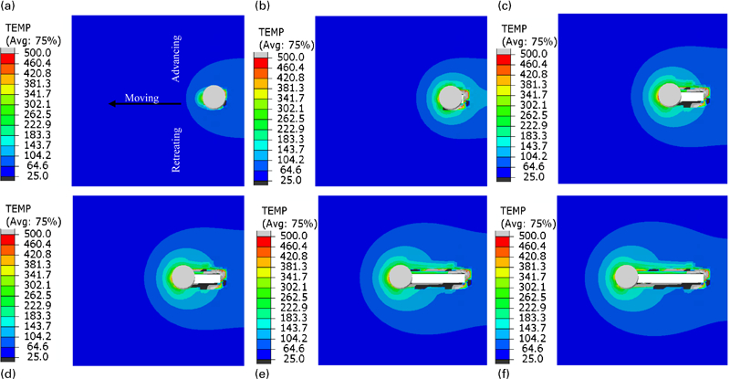
Temperature contours of top surface of welded plate at different times of moving stage
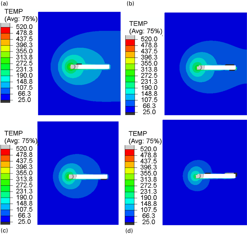
Effect of BCCs of back plate on temperature field
Figure 5 shows the temperature fields on the top surface of the plate at 45 s under different BCCs. The temperature field without heat loss from the back plate was also calculated for comparison, as shown in Fig. 5a. It was clearly observed that all the isotherms, especially the peripheral ones, gradually shrank, taking the tool as the centre with the increase in BCC. However, as the BCC exceeded 1500 W m−2 K−1, the heat affected zone changed a little. The reason was that more heat was dissipated from the vicinity of the tool as the heat convective coefficient increased, and thus, the apparent shrinkage of the high temperature zone occurred. Consequently, the temperature gradient around the tool increased. The effect of the BCC on the temperature field on the bottom surface of the plate is shown in Fig. 6. Similarly, the high temperature zone obviously shrank towards the vicinity of the tool when the BCC increased. It should be emphasised that different BCCs may correspond to different materials of the back plates. The convection effect may vary with the pressure and temperature across the transverse direction of the plate. Therefore, the back plate may play an important role in the property of the resultant joints.
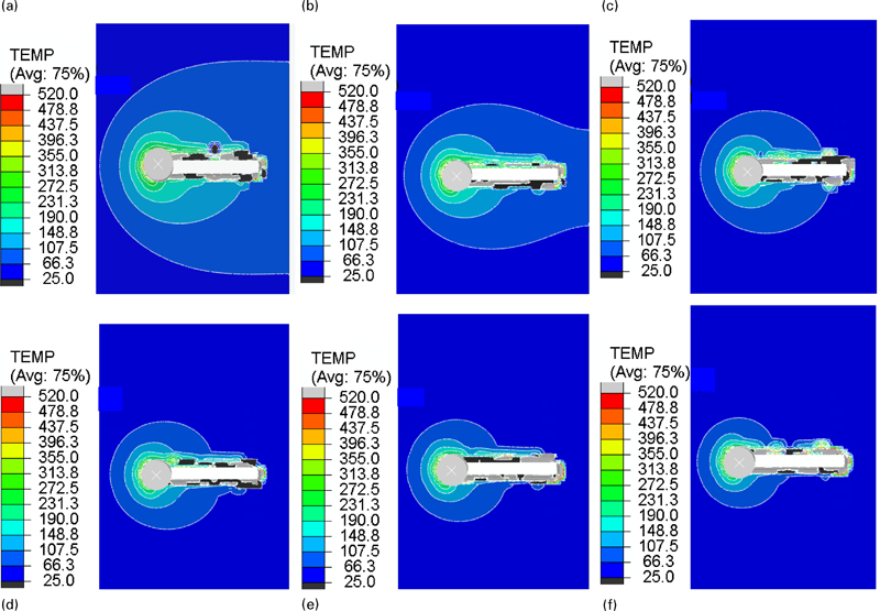
Effect of BCC on thermal history of top surface at 45 s
Effect of BBC on temperature field of bottom surface of welded plate
Conclusions
In the plunge stage of FSW, the high temperature zone moved from the region beneath the pin to the corner area formed by the shoulder and welded plate. Subsequently, the temperature symmetrically distributed across the cross-section of the plate, and the temperature contour in the weld nugget zone presented a V type shape. In the dwell stage, the frictional heat at the contact interface conducts around to preheat the plate. While in the moving stage, the heat gradually accumulated to form a quasi-stable temperature field around the tool pin.
The temperature isotherms on both top and bottom surfaces of the plate gradually shrank, taking the tool as the centre with increasing BCC.
Footnotes
Acknowledgements
The authors would like to gratefully appreciate the financial supports from the Ao-Xiang Star Project of Northwestern Polytechnical University (NPU), the Research Fund of the State Key Laboratory of Solidification Processing (NPU, China) (grant no. 69-QP-2011), the Program for New Century Excellent Talents in University by the Ministry of Education of China (grant no. NECT-08-0463), the National Natural Science Foundation of China (grant no. 51005180) and the 111 Project (grant no. B08040).