
Abstract
The influence of aluminium upon continuous cooling transformation (CCT) diagrams for hot rolled ferrite–martensite dual phase steel is investigated, with continuous cooling experiments performed through the use of dilatometry. Results indicate that additions of aluminium significantly raise the Ar3 and Ar1 temperatures accounting for the increased polygonal ferrite stabilisation during cooling. Acceleration of ferrite transformation is observed, with aluminium displacing both ferrite and pearlite transformations to the left of the CCT diagram. Aluminium is also seen to suppress bainite formation and decrease the martensite start temperature by increasing the hardenability within austenite grains.
Introduction
Hot rolled ferrite–martensite dual phase steels are increasingly being used within the production of lightweight automotive wheel discs,1,2 with impending growth within chassis and suspension components, as demonstrated through the UltraLight Steel Auto Suspensions project.3 Driving this substitution from more conventional high strength low alloy steels to higher strength multiphase steels is the implementation of strict European regulations regarding the average CO2 emissions that can be generated, being enforced throughout the automotive sector between 2012 and 2015.4
Ferrite–martensite dual phase steels offer attractive combinations of high tensile strength with good uniform elongation and stretch formability, providing an effective solution for down gauging and weight reduction. Although edge ductility issues are not seen as a problem for most wheel, chassis and suspension components, issues may arise when utilising dual phase steel for more demanding, higher complexity parts where superior formability is required. As such, both academic and industrial researches are currently focused on increasing the overall formability within dual phase steels with emphasis on the production of a transformation induced plasticity (TRIP) assisted dual phase product.
The TRIP steels demonstrate superior elongation values as well as higher workhardening exponents that persist at higher strain rates, which are attributed to the decomposition of retained austenite to martensite during plastic deformation. Introducing a small volume fraction of retained austenite within the microstructure of conventional cold rolled dual phase steel has shown improvements in localised ductility and stretch flangeability;5 thus, a small volume fraction of retained austenite within the as rolled condition warrants further investigation.
Studying TRIP steel production, significant additions of silicon (1–2·5 wt-) are made to produce a carbide free bainitic structure. The prevention of cementite and carbide precipitation during the bainitic isothermal transformation ensures carbon enrichment of the remaining (untransformed) austenite grains, thus producing approximately 10–20 retained austenite within the final structure. Significantly alloying with silicon, however, creates surface quality issues with the formation of red scale and tiger stripes that are challenging to remove from the as rolled coil and undesirable for surface critical applications such as wheel discs. Recent research therefore has focused on the theory of preventing both cementite and carbide precipitation but through the use of alternative alloying additions.1,6,7
One such alloying addition that, like silicon, has negligible solubility within cementite is aluminium.8 It is thought that as aluminium is essentially insoluble within cementite and other carbide precipitates, carbon will be able to remain within the solid solution in the remaining austenite grains, thus increasing the grain carbon concentration, suppressing Ms to below room temperature and allowing austenite stabilisation. Aiding in further carbon enrichment within austenite before cooling is the ability of aluminium additions to promote ferrite stabilisation. By accelerating nucleation and growth to shorter timescales as well as raising the Ar3 temperature, further carbon enrichment of austenite can occur during the three-stage cooling procedures that are necessary to produce hot rolled dual phase steel.
If carbide precipitation can be fully retarded, and the carbon concentration within the austenite grains is sufficient to lower the Ms temperature, potentially a higher percentage of austenite can be stabilised within the final microstructure compared to conventional Dual Phase (DP) grades. To determine the potential of aluminium to lower the Ms and to determine the optimum processing conditions to aid in laboratory hot rolling, the present work focuses upon the production of two continuous cooling transformation (CCT) diagrams studying the effect of 0·85 wt- aluminium compared to the base material that has residual aluminium levels of 0·029wt- from the deoxidising process.
Experimental
The two chemical compositions used within the present investigation (Table 1) are based on a C–Mn–Cr–P concept that has previously been found to offer the best potential for achieving desirable dual phase properties.1,9 These steels were prepared under vacuum conditions as 30 kg laboratory ingot casts, followed by laboratory scale roughing to ∼38 mm wide slabs, with samples being cut and machined for dilatometry.
Chemical compositions of steels A and B, wt-
Initial Ar3 determination experiments were carried out upon both steels A and B, with experimental results revealing that aluminium additions increase the ferrite stability at elevated temperatures. As such, within the dilatometry thermomechanical cycles, two different finishing temperatures (FTs) were used: 850°C for steel A and 920°C for steel B to essentially prevent ferritic rolling of the samples. S-type thermocouples were attached to the 5×10 mm cylindrical samples through spot welding, allowing temperatures to be recorded. Samples were reaustenitised within a Bahr 805 A/D dilatometer at 1250°C for 300 s and then cooled at 1°C s−1 to 1100°C, where an initial 30 deformation was performed on the sample through the use of quartz punches. The samples were then cooled at 1°C s−1 to the two different FTs, where a second 30 deformation was exerted onto the sample. After the second deformation sequence, a 5 s time delay was employed to simulate the time from the seventh finishing stand to that of the first spray on the runout table; the samples were then cooled at six different cooling rates ranging from 2 to 60°C s−1 to 100°C.
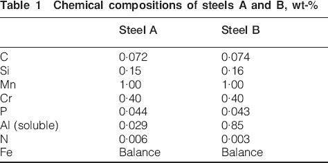
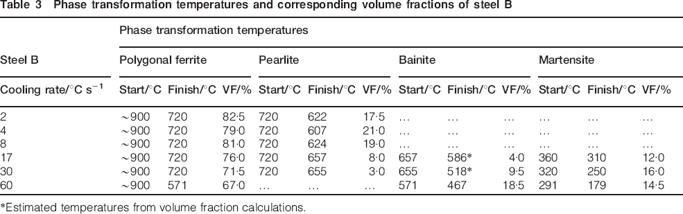
The generation of each of the CCT diagrams involved the preparation of all the experimental samples through standard metallographic techniques with micrographs recorded through optical microscopy, thus allowing the identification of the microstructural phases produced. Volume fraction analysis of each of the phases present was measured using a manual point counting technique, as described in ASTM standard E562.10 These measurements, in conjunction with the dilatation curves generated for each of the samples, were then used to indicate the position of phase boundaries on the CCT diagrams. For example, Fig. 1b demonstrates one particular dilatation curve for steel A at a cooling rate of 30°C s−1. From studying the dilation curve, the ferrite phase transformation can be detected to start at 739°C s−1 and finish at 487°C s−1, whereas the martensite transformation has a start temperature of 420°C s−1 and a finish temperature of 379°C s−-1. Supplementary work with volume fraction analysis reveals that the ferrite transformation can be further distinguished into polygonal and lath ferrite along with the presence of bainite (Fig. 1g). From this, indicative phase transformation boundaries can be added to the CCT diagram, but as different phases result in different volume expansions due to the different mechanisms that are required for them to form, the dotted lines are intended to provide a guide and not to be taken as ultimate values.
Dilatation curves obtained for steel A after cooling from FT of 850°C with rates of a 2°C s−1 and b 30°C s−-1 and microstructures of c 2°C s−1, d 4°C s−1, e 8°C s−1, f 17°C s−1, g 30°C s−1 and h 60°C s−1
Results and discussion
When steel A is cooled under a variety of different cooling rates from 2 to 60°C s−1, a diverse range of microstructural phases are produced from ferrite–pearlite microstructures at lower cooling rates to that of solely bainitic at faster speeds. Table 2 and Fig. 1 indicate these microstructural phases present within each of the dilatometry samples, illustrating the temperatures at which the relative phase transformations occur and their resultant volume fractions. As an example for the slowest cooling rate of 2°C s−1, polygonal ferrite formation is detected from the dilatation curve at a temperature of 822°C, with the transformation concluding at 660°C (Fig. 1a). At this temperature, ferrite continues to form but with alternate layers of cementite, with pearlite dissolution detected between 660 and 603°C on the dilatation curve. Optical microscopy confirms the dilatometry traces, as seen within Fig. 1c, illustrating a polygonal ferrite and pearlite microstructure with a volume fraction of 18·0 pearlite (Table 2).
Phase transformation temperatures and corresponding volume fractions of steel A
*Estimated temperatures from volume fraction calculations.
At cooling rates of 4 and 8°C s−1, ferrite and pearlite microstructures are produced (Fig. 1d and e), with decreasing transformation temperatures and pearlite volume fractions when compared to the slowest cooling rate (Table 2). However, within the 4°C s−-1 sample, solely polygonal ferrite formation is observed compared with additional lath ferrite and bainite structures within the higher cooling rate of 8°C s−1 (Fig. 1e).
For higher cooling rates of 17–60°C s−1, both dilatation traces and corresponding microstructures (Fig. 1f–h) show minimal polygonal ferrite formation and no pearlite colonies, being replaced instead by increased volume fractions of lath ferrite and bainite. It is observed that the volume fractions of lath ferrite and bainitic structures increase as the cooling rate increases, as documented in Table 2, with the maximum volume fraction of 97·5 being recorded for the highest cooling rate of 60°C s−1. The formation of martensite is seen to form at the two highest cooling rates of 30 and 60°C s−-1, with the dilatation traces showing the Ms temperature at 420 and 305°C, respectively, this accounting for 2·5 volume fraction within each of the samples.
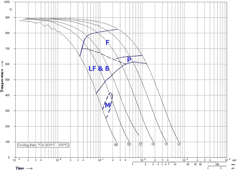
Studying the effect of cooling rate on steel B reveals that at slower cooling rates, a ferrite–pearlite microstructure is forming, while at faster cooling rates, substantial volumes of polygonal ferrite are still present within the microstructure, when compared to the microstructure of steel A. It is observed that aluminum increases the ferrite stability, as within all samples, polygonal ferrite formation is seen to begin within the region of 900°C, as observed in Fig. 2a and Table 3. Pearlite formation is also seen to be elevated to higher temperatures with its formation detected at 720°C within all samples apart from the highest cooling rate of 60°C s−1.
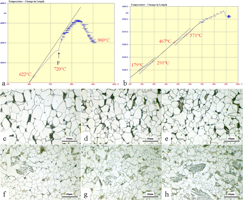
Dilatation curves obtained for steel B after cooling from FT of 920°C with rates of a 2°C s−-1 and b 60°C s−1 and microstructures of c 2°C s−1, d 4°C s−1, e 8°C s−1, f 17°C s−1, g 30°C s−1 and h 60°C s−1
Phase transformation temperatures and corresponding volume fractions of steel B
*Estimated temperatures from volume fraction calculations.
For the lowest three cooling rates of 2, 4 and 8°C s−1, a polygonal ferrite and pearlite microstructure is observed with phase transformations occurring at 900 and 720°C respectively (Fig. 2a and c–e). As the cooling rate increases to 17 and 30°C s−1, pearlite dissolution still occurs at the same temperature; however, the phase volume fraction decreases from ∼20 to minimal percentages of 8 and 3. The predominant second phase present within each of these samples is martensite, with volume fractions of 12 and 16 being recorded; however, there is a small fraction of bainite apparent within coarser grained structures, where the outer peripheral region consists of martensite (Fig. 2f and g). As with 17 and 30°C s−1, the sample with the highest cooling rate of 60°C s−-1 reveals a polygonal ferrite matrix with the formation of coarse clumps of bainite and finer grains of martensite. However, unlike previous cooling rates, pearlite formation is not observed through the dilatation trace (Fig. 2b) and microstructure (Fig. 2h).
In Figs. 3 and 4, CCT diagrams complied from the investigation are shown. It can be seen that aluminium raises the Ar3 temperature coinciding with literature,6,11 stabilising ferrite formation at both higher temperatures and shorter timescales as demonstrated by the acceleration of the ferrite nose to faster cooling rates along with the increased volume fractions of measured polygonal ferrite. In conjunction with the increased Ar3 temperature, an increase of 60°C in Ar1 temperature is observed from 660°C within steel A to 720°C within steel B, conflicting with published literature that finds aluminium additions to have little effect on raising the transformation temperature of pearlite.11 The microstructures also reveal that pearlite formation is shifted to shorter timescales on the CCT diagram, with its formation detected at 17°C s−-1 within the 0·85 wt- aluminium steel compared to pearlite formation restricted to lower cooling rates of 8°C s−1 and below within steel A. This apparently contradicts the literature that states that aluminium additions displace the pearlite transformation to the right of a CCT diagram.1,12
Continuous cooling transformation diagram of steel A after cooling with rates of 2–60°C s−1 from FT of 850°C
Continuous cooling transformation diagram of steel B after cooling with rates of 2–60°C s−1 from FT of 920°C
The suppression of lath ferrite and bainite formation is observed within the CCT diagram for steel B, with the substitution of lath ferrite to bainitic ferrite within the microstructures studied. At higher cooling rates, lath ferrite and bainite are solely present within steel A; however, within the microstructures of steel B, a polygonal ferrite matrix is predominately present with coarse dispersions of carbide free bainite and martensite second phase.
The absence of lath ferrite and predominately bainite microstructures within steel B is due to the effect aluminium has on ferrite stabilisation. The decomposition of austenite to ferrite involves a reconstructive transformation of both interstitial and substitutional atoms through the process of diffusion. Diffusion is time dependent, and therefore, within steel A, where ferrite stabilisation occurs at lower temperatures, the period for ferrite transformation is shorter compared to that in steel B, where the ferrite transformation begins instantaneously at 900°C. The rate of diffusion is also temperature dependent, with lower temperatures and large undercoolings affecting the morphology of ferrite. At low undercoolings, polygonal ferrite is present; however, as undercoolings increase, the formation of lath ferrite is observed. Studying higher cooling rates of 30°C s−1, ferrite transformation within steel A starts at a low temperature of 739°C compared to the transformation at 900°C within steel B. Within steel A, the initial undercooling is low, as the Ar3 recorded is 822°C; therefore, polygonal ferrite forms within the structure. However, after a period of a couple of seconds due to the fast cooling rates, a large undercooling occurs, resulting in minimal polygonal ferrite and the formation of lath ferrite, as observed in Fig. 1h. In the case of steel B, however, as the decomposition of austenite to ferrite begins, polygonal ferrite has an increased period of time to form. As cooling proceeds, the growth of polygonal ferrite continues, and before large undercoolings are reached due to the high temperatures at which ferrite is stabilised, the polygonal ferrite transformation is complete, producing a polygonal ferrite matrix (Fig. 2f–h). As such, aluminium accelerates the rate of ferrite formation, as diffusion of interstitial and substitutional atoms can occur at higher temperatures, shorter timescales and therefore longer periods of time, thus enabling reconstructive transformation mechanisms to occur, as seen within steel B that produces polygonal ferrite matrixes instead of lath ferrite and bainitic ferrite structures in steel A.
As discussed, the formation of bainite within the higher cooling rates (30–60°C s−1) of steel B occurs within areas of coarse grain structure (Fig. 2g–h), where martensite is present around the peripheral region of the grain. However, in regions where ferrite grains are finer, only martensite second phase is present. Within these regions during ferrite growth, the rate of carbon diffusion is high due to the smaller distances over which the interstitial carbon atoms have to diffuse. The smaller distances and finer remaining austenite grains therefore have a higher carbon concentration, increasing the hardenability of austenite; therefore, during continued cooling, bainite formation is retarded, and martensite formation occurs. In areas of coarser grain structures, as carbon has to diffuse over larger distances, there is insufficient carbon enrichment to suppress bainite formation throughout the entire coarser austenite grain. Therefore, martensite is seen within the peripheral regions where sufficient carbon concentrations arise, but as seen within the centre of the grain where carbon concentrations are lower, bainite formation occurs due to the lack of hardenability, as reported by Evans et al.13 and seen in Fig. 5.
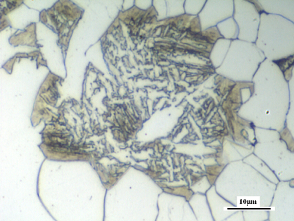
Microstructure of steel B when cooled at rate of 30°C s−1, illustrating bainite formation within centre of former austenite grain with martensite formation at peripheral region enriched with carbon
By comparing both CCT diagrams, it is observed that the addition of 0·85 wt-Al is responsible for decreasing the martensite transformation temperatures. Within the present investigation, it is seen that the Ms at 30°C s−1 within steel A is 420°C compared to a lower temperature of 320°C for steel B at the corresponding rate of cooling. This decrease in Ms is also observed at the highest cooling rate of 60°C s−-1, with steel A giving an Ms of 305°C and steel B of 291°C. The literature, 1 1,12 however, concludes that aluminium additions raise the Ms temperature within steels. The decrease in Ms temperature is once again due to the effect Al additions have on ferrite stabilisation at elevated temperatures. Within steel B, ferrite formation occur at higher temperatures, within shorter timescales and therefore longer periods of time, producing a polygonal ferrite matrix as discussed. Owing to the high volume fractions of polygonal ferrite measured, an increased carbon concentration within the remaining austenite grains must occur compared to steel A that has minimal polygonal ferrite formation. Carbon ultimately controls the martensite start temperature, and as a result of the increased enrichment of the austenite grains in steel B because of the increase polygonal ferrite formation, the Ms is recorded to be lower than that in steel A as the carbon present within these microstructures is seen as carbide precipitates between the laths of ferrite and bainite and not within any remaining austenite. Thus, steel A has a lower carbon concentration and a lower hardenability within the austenite grains, which leads to a higher Ms being recorded.
Conclusions
Additions of 0·85 wt- aluminium increase both Ar3 and Ar1 temperatures when comparisons are made with the base chemistry that contains residual amounts of aluminium from the deoxidising process. The ferrite transformation is seen to start at 900°C within all samples of steel B; however, within steel A, ferrite formation is suppressed to lower temperatures as cooling rates increase with the highest Ar3 recorded at 822°C when a cooling rate of 2°C s−1 is applied. In addition, aluminium displaces pearlite formation to the left of the CCT diagram, contradicting published literature.1,12
Further contradiction is reported with the decrease in Ms temperature being discussed with reasoning to why aluminium additions decrease the martensite transformation temperature related to the increased ferrite stabilisation that aluminium additions provide. As polygonal ferrite formation occurs over longer periods of time and at higher temperatures, further carbon enrichment takes place within the remaining austenite grains. This increased carbon concentration increases the hardenability within austenite grains; thus, suppression of the Ms temperature is observed.
Footnotes
Acknowledgements
The authors gratefully acknowledge the dilatometry work carried out by Mr A. Sayles, Tata RD&T, and the funding from EPSRC and TSSPUK.