
Abstract
High Mn twinning induced plasticity (TWIP) steel is a new type of structural steel, characterised by both high strength and superior formability. TWIP steel offers an extraordinary opportunity to adjust the mechanical properties of steel by modifying the strain hardening. The use of TWIP steel may therefore lead to a considerable lightweighting of steel components, a reduction of material use and an improved press forming behaviour. These key advantages will help implement current automotive vehicle design trends which emphasise a reduction of greenhouse gas emissions and lowering of fuel consumption. In addition, high strength TWIP steel will effectively contribute to weight containment in vehicles equipped with hybrid and electric motors, as these are considerably heavier than conventional motors. The present review addresses all aspects of the physical metallurgy of the high strength TWIP steel with a special emphasis on the properties and key advantages of TWIP sheet steel products relevant to automotive applications.
Introduction
Increased overall vehicle quality improvements have resulted in passenger cars which have steadily gained in weight. This weight spiral is a direct result of improved vehicle safety and increased space combined with enhanced performance, reliability and passenger comfort. Carmakers are increasingly building passenger cars with body-in-white (BIW) designs which emphasise passenger safety. The safety issue directly related to BIW materials is passive safety. High impact energy absorption is required for frontal crash and rear collision, and anti-intrusion properties are required in situations when passenger injury must be avoided, i.e. during a side impact and in case of a rollover, with its associated roof crush. The weight issue is also high on the agenda of BIW designers, as it is directly related to environmental concerns, i.e. CO2 emission and the efficient use of non-renewable fuels. Steel based part design using advanced high strength steel (AHSS) offers the potential for a combination of increased passenger safety and vehicle mass containment at lower production costs. Hence, when material specific properties are considered, there is an increasing interest in very high and ultra high strength (ultimate tensile strength, >1 GPa) materials. Dual phase and transformation induced plasticity (TRIP) steels are now well established as AHSS, with major applications in BIW parts related to crash energy management. In the case of dual phase grades, the emphasis is on front–end applications and exterior panels. The use of dual phase and TRIP steels has been reported to result in a weight saving in the range of 10–25. The potential for weight reductions becomes very important when ultra high strength steels are considered, and weight reductions in the range of 30–40 are possible for 1300–1500 MPa steels. Strength levels in the range of 1800–2000 MPa have been mentioned as future requirements for anti-intrusion parts. An ultra high strength, a high stiffness, and only very low levels of collision related deformations, typically less than 5, are allowed for these parts. Hot press forming 22MnB5 grades are increasingly being used for B pillar and front–rear reinforcements.
Strength is often achieved at the expense of formability, and a global steel research effort is currently underway focusing on TWIP steel, which offers an extraordinary opportunity to adjust the mechanical properties by modifying the strain hardening. Figure 1 compares the mechanical properties of 1 GPa TWIP steel with the properties of common ferritic and austenitic sheet steel grades routinely used to manufacture press formed parts. Figure 2 compares the strain hardening behaviour of 1 GPa TWIP, high strength interstitial free (IF) and TRIP steels. TWIP steel has twice the uniform elongation than that of TRIP steel and considerably higher ultimate strength. This unusually high strain hardening leads to superior press forming performance, which is very convincingly illustrated in Fig. 3. The strain hardening mechanism in TWIP steel, illustrated in the schematic of Fig. 4, is best described as a ‘dynamical Hall–Petch effect’. The dominant deformation mode in TWIP steel is still dislocation glide but, in the dynamical Hall–Petch effect, mechanical twins are also continuously being formed during straining. As the formation of mechanical twins involves the creation of new crystal orientations, the twins progressively reduce the effective ‘mean free path’ or effective glide distance of dislocations and increase the flow stress. The gradually increasing twin density results in the very high strain hardening observed in TWIP steel. The key to twin formation lies in the precise control of the stacking fault energy (SFE): if the SFE is <20 mJ m−2, strain induced transformation is more likely to take place; if the SFE is >50 mJ m−2, the formation of twins is suppressed.
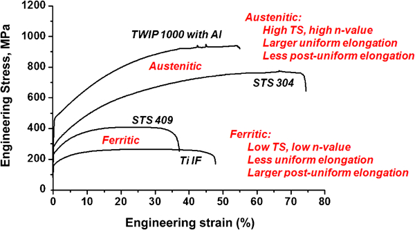
Comparison of mechanical properties of 1 GPA TWIP steel with properties of common ferritic and austenitic sheet steel grades
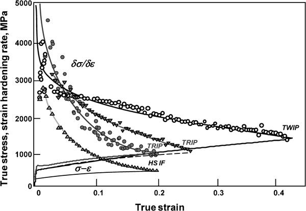
Comparison of strain hardening behaviour of high strength IF, TRIP and TWIP steels
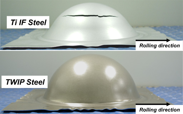
Comparison of Nakashima test samples for IF and TWIP steels
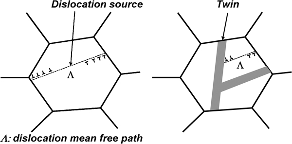
Schematic of strain hardening mechanism in TWIP steel
The focus of the present review is on high Mn austenitic TWIP steel with a Mn content in the range of 12–30 mass.1–4 These relatively high Mn ferrous alloys are characterised by strength–ductility products in the range of 40·000–60·000 MPa . The main alloying additions to TWIP steel are C, Mn, Al and, in some cases, Si. The C, Mn, Al and Si contents are precisely controlled to obtain a SFE of 20–50 mJ m−2. The C additions, typically in the range 0·4–1·0 mass-, also result in the stabilisation of the austenite phase and solid solution strengthening.
Note that TWIP steel has a different alloy design concept from the one used for high Mn austenitic specialty steels which are currently already being produced industrially, such as wear resistant steel (e.g. X120Mn12 with 12 mass-Mn), cryogenic steel (e.g. X40MnCr22 with 22 mass-Mn), Ni free stainless steel (e.g. AISI 205 with 14–15·5 mass-Mn), non-magnetic steel (23–25 mass-Mn), high damping steel (17 mass-Mn) and shape memory steel (Fe–Mn–Si alloys with 28 mass-Mn).
The early scientific work on high Mn ferrous alloys1–3,5–8 did not receive much industrial attention originally. In addition, there were considerable difficulties during the first attempts to process TWIP steel industrially a few years later. The perception that TWIP steel was prone to delayed fracture and dynamic strain aging (DSA), made the initial industry efforts to develop TWIP steel even more challenging. Two factors have recently resulted in a renewed industry wide interest in high Mn TWIP steel:
the discovery of the beneficial effects of Al additions on the suppression of the delayed fracture phenomenon
the strong demand for formable ultra high strength steels from the automotive industry.
By 2008, three types of TWIP steel composition had been extensively investigated: Fe–25–30Mn–3Si–3Al,1 Fe–22Mn–0·6C,9 and Fe–18Mn–1·5Al–0·6C.10
At present, cost considerations and the marked improvement of the mechanical properties of TWIP steel with a reduced Mn content are the main drivers in TWIP steel research. New, leaner, compositional designs for TWIP steel have been proposed and the current worldwide efforts in the development of TWIP steel suggest that industrial production of TWIP sheet steel will very likely focus on TWIP steel with ∼15 mass-Mn. Examples of industrial TWIP steel with 15 mass-Mn which had been developed by early 2009, include the following alloys: Fe–15Mn–2·0Al–0·6C–0·5Si,11 Fe–15Mn–3·0Al–0·7C,12,13 Fe–15Mn–2·5Al–0·7C,14 Fe–15Mn–2·5Si–2·5Al–0·6C, Fe–15Mn–2·5Al–0·6C,15 and Fe–16Mn–0·6C–0·2Si–0·2Al.16 Research efforts are currently underway to evaluate the performance of various 12 mass-Mn TWIP steel variants. Examples include the following alloys: Fe–12Mn–0·8C,17 and Fe–12Mn–2Si–0·9C.18
The potential applications for Mn TWIP steel will very likely not be limited to the automotive industry, i.e. for applications in passenger cars, light trucks and commercial vehicles such as vans and heavy trucks. Additional applications may exist in other transportation areas (street cars, buses, trains and railcars), line pipe production, ship building and in special applications which require non magnetic panels.
Thermodynamic properties of TWIP steel
The Fe rich side of the Fe–Mn equilibrium phase diagram is relatively simple, with an open γ loop,19 but the microstructures of actual Fe–Mn alloys shown in Fig. 5 reveal that in the range of 5–25 mass-Mn, the microstructure of Fe–Mn alloys is dominated by the presence of α′ martensite, at a low Mn content, and ϵ martensite, at a higher Mn content. Approximately 27 mass-Mn is required to obtain metastable austenite at room temperature. Relatively small C additions of 0·6 mass- result in martensite free, austenitic microstructures for Mn contents as low as 12 mass- (Fig. 5). The microstructure of TWIP steel is single phase austenitic, with relatively coarse grains, which often contain wide recrystallisation twins. Al is added to control the SFE of TWIP steel. Al also suppresses the formation of the carbide Fe3C. The Al additions, typically less than 3 mass-, also result in a slight reduction in density. This is due to the combined effect of the lower molecular weight of Al and the increase of the lattice parameter by Al additions. An alternative approach to obtain TWIP steel with a uniform, carbide free, austenitic microstructure is to use a higher Mn content and avoid C additions. This TWIP steel composition concept typically requires Si and Al additions to control the SFE. The importance of the Al additions to TWIP steel cannot be underestimated as it results in much improved TWIP properties. Jung et al.20 have shown that small additions of Al facilitated the TWIP effect and the formation of ϵ martensite was effectively suppressed by the addition of 1·5 mass-Al to Fe–15Mn–0·6C TWIP steel. Nitrogen has been found to have similar effects as Al.22
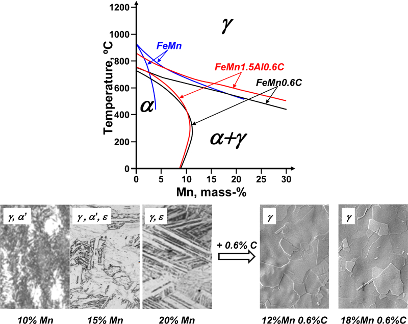
Pseudobinary phase diagrams for various Fe–Mn alloys (top). In contrast to what is predicted by the equilibrium phase diagram, the room temperature microstructure of binary Fe–Mn alloys is dominated by the formation of α′ and ϵ martensite. These transformations are suppressed by alloying additions of C (below)
Stacking fault energy
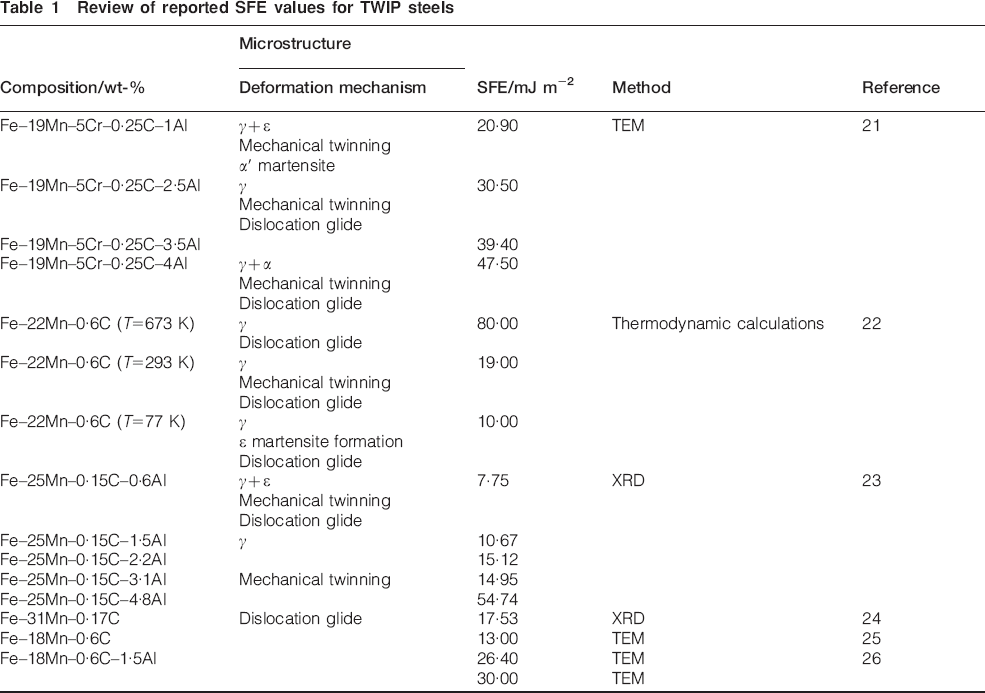
The SFE is a key factor controlling the mechanical properties of the high Mn alloys. The SFE plays an essential role in the occurrence of the TWIP effect, and the SFE which is most often reported to be required for an TWIP effect is 20–50 mJ m−2. It is still unclear why this minimum ‘magic number’ is essential for the occurrence of the strain induced twinning, but it appears to be related to the suppression of the athermal γ→ϵ martensitic transformation (Fig. 6). As the SFE is an essential parameter, there has been a considerable interest in determining its value for TWIP steels. SFE values for TWIP steels, taken from the literature, are listed in Table 1.22–27
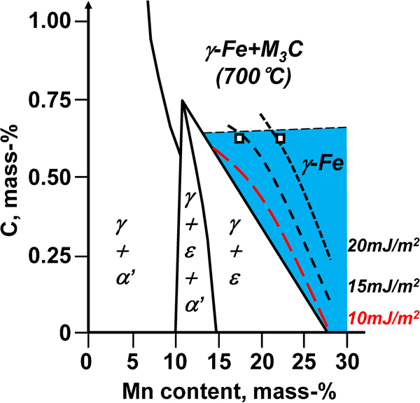
Schematic showing relationships between composition, SFE and phases present at room temperature after quenching from annealing temperature of 700°C
Review of reported SFE values for TWIP steels
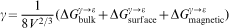
From a theoretical point of view, the SFE is proportional to the fcc and hcp free energies difference ΔGγ→ϵ. The contributions from the interfacial energy  and the magnetic energy
  , to the SFE need to be taken into account as they may have a significant influence
Al increases the SFE and very effectively suppresses the γ→ϵ transformation. Jin et al.31 mentioned that a SFE value of 33 mJ m−2 is required to obtain twinning in Fe–18Mn–0·6C–1·5Al. Recently, Kim et al.27 reported that the SFE of Fe–18Mn–0·6C–1·5Al TWIP steel was 30 mJ m−2. The SFE for Fe–Mn–Si–Al TWIP steel has been also studied by Huang et al.32 They have also studied the effect of 0·011–0·052 nitrogen on the SFE of Fe–(20·24–22·57)Mn–(2–3)Si–(0·69–2·46)Al containing 100 ppm C, by means of XRD. Their results indicate that Al and N increase the SFE and decrease the stacking fault formation probability. Dumay et al.30 have shown that Al increases the SFE by about +5 mJ m−2 per added mass-Al. Si also increases the SFE by about +1 mJ m−2 per mass-Si. These results are contradicted by Tian et al.33 who measured the SFE for Al added Fe–25Mn–0·7C steel. They report a much smaller SFE increase of about +1·4 mJ m−2 per added mass-Al.
Wang et al.34 have remarked that although there is a general consensus that the SFE is an essential parameter, it is by no means proven that it is the single most important parameter controlling the TWIP mechanism. They noticed that only a small SFE difference of 5–10 mJ m−2 caused an apparently sharp transition from strain induced ϵ martensite formation to strain induced twinning.
The question is further complicated because there is no clear relationship between the SFE and the twinning mechanism operating in TWIP steel. Recent experimental measurements of the nature of the stacking faults have resulted in the suggestions that ϵ martensite formation and mechanical twinning is mediated by the extrinsic stacking fault (ESF) and the intrinsic stacking fault (ISF) respectively. Idrissi et al.35 studied the deformation mechanism of a two phase α+γ Fe–19·7Mn–3·1Al–2·9Si steel. Deformation at 86 and 160°C resulted in ϵ martensite and twinning at lower temperatures, and exclusively mechanical twinning at the higher temperatures. At room temperature, only ϵ martensite was observed. They argued that this was due to the presence of ESFs at lower temperatures acting as precursors to ϵ martensite formation and ISFs at higher temperatures acting as twin precursors.
Based on this, thermodynamic models are available which predict the SFE correctly for the quaternary Fe–Mn–Al–C alloy system.36 A comparison of calculated and experimentally determined SFEs for Fe–Mn–Al–C TWIP steel is shown in Fig. 7.
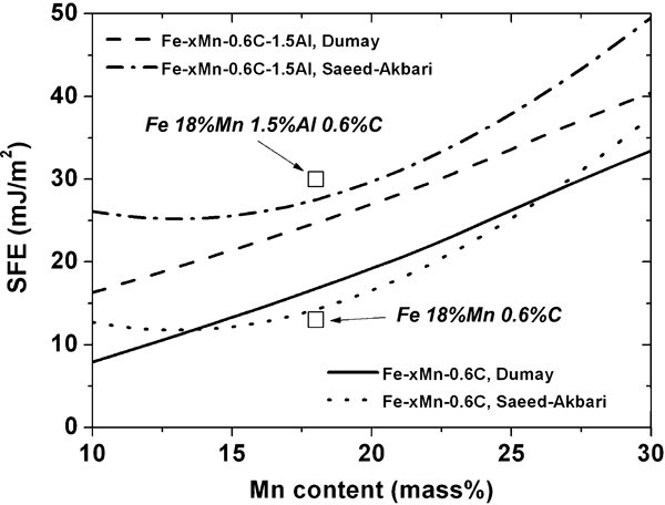
Comparison of calculated and experimentally determined SFE for Fe–xMn–0·6C and Fe–xMn–1·5Al–0·6C TWIP steels
Mechanical properties of TWIP steel
Fe–Mn alloys are characterised by the occurrence of complex deformation phenomena: strain induced α′ martensite formation, ϵ martensite formation, deformation twinning, pseudotwinning, extended dislocation glide and perfect dislocation glide. The dominant deformation mode is dislocation glide but the process is strongly influenced by these complex phenomena. The best way to gain insight into the deformation behaviour of TWIP steels is by TEM studies, as the twinning microstructure is very fine. This is illustrated in Fig. 8. At low strains, the dislocation density increases and the grain boundaries seem to be particularly effective source of isolated stacking faults. The onset of twinning requires multiple slip within deformed grains. The strain induced twins have a high aspect ratio and cross the entire grain. At 20 strain, the high dislocation density between the deformation twins clearly shows that twin boundaries act as effective barriers for dislocation movement. High resolution TEM has clearly shown that the twins are very thin and there may be continuous nucleation of new deformation twins of decreasingly smaller size. Consequently, the twin volume fraction does not represent a large portion of the total volume.
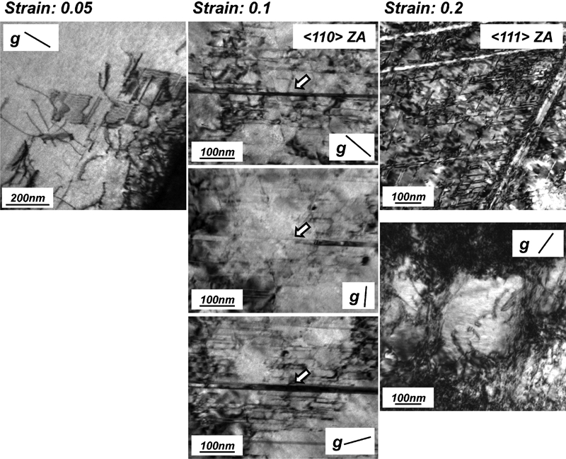
Images (TEM) of TWIP steel after 5, 10 and 20 of strain. In the initial stages of deformation (left), the dislocation density increases and there is no formation of twins. In addition, some grain boundaries emit bundles of stacking faults. At a higher strain (middle), narrow strain induced twins cross the entire grain. At a very high strain (right), TWIP steel develop a dislocation cell structure and arrays of stacking faults in the regions between twins
Although the role of deformation induced twins will mainly be discussed in the following paragraphs, it must not be forgotten that the rate of dislocation accumulation will automatically increase when an alloy has a low SFE, independently of twin formation, as the larger dissociation width will more effectively reduce the cross-slip and result in a higher rate of dislocation accumulation.
Whereas the TWIP steel has a high strain hardening, it also has a relatively low yield stress. Grain size reduction and solid solution hardening can be used to obtain higher yield strengths for applications where this is required. The grain size dependence of the yield strength σ (MPa) has been reported to follow the Hall–Petch relationship37


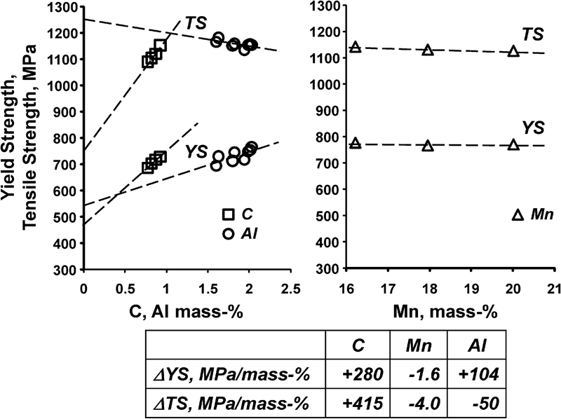
Solid solution hardening of TWIP steel by C, Mn and Al. The solution hardening coefficient for C in the table is based on the data from Fe–15Mn–2Al–xC alloys. The coefficient for Mn is based on the data from Fe–xMn–2Al–0·7C alloys. The coefficient for Al is based on the data from Fe–15Mn–xAl–0·9C alloys
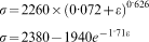
The following Swift and Voce equations, which have been derived by Barlat and co-workers,40 clearly point to the pronounced work hardening of TWIP steel
A micromechanical model incorporating elasto-viscoplasticity was developed by Shiekhelsouk et al.45 for Fe–22Mn–0·6C TWIP steel. They reported that the twinned volume fraction was dependent on the grain orientation, and less than 0·08 for a macroscopic strain of 0·4. This is in disagreement with the large twin volume fraction of 0·56 at a strain of 0·4 reported by Dini et al.,37 who analysed the dislocation density evolution in Fe–31Mn–3Al–3Si TWIP steel during straining by means of XRD.
In the model of Kim et al.,46 based on the Kubin–Estrin approach,47 the strain hardening is computed from the evolution of the coupled densities of the mobile dislocations and immobile forest dislocations. A typical result for Fe–18Mn–0·6C–1·5Al TWIP steel is shown in Fig. 10.
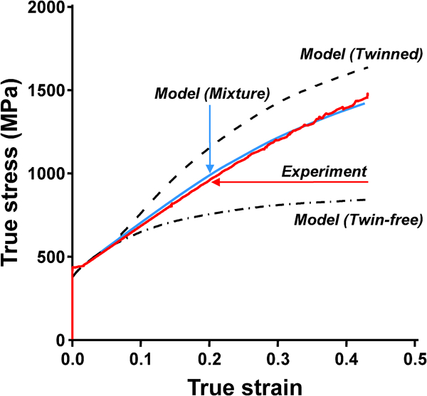
Comparison of experimental and calculated stress–strain curves for twin free grains, twinning grains and ‘phase mixture’ model for Fe–18Mn–1·5Al–0·6C TWIP steel
Although Xu and Barlat48 have recently shown that the work hardening of 980 MPa Fe–Mn–Al–C TWIP steel is almost isotropic up to a longitudinal plastic strain of 0·24, the strain hardening of TWIP steel is very likely not isotropic over the full deformation path, as there are clear indications of kinematic hardening at larger strains. Sevillano49 has argued that the observation of the Bauschinger effect in TWIP steel is due to the simultaneous deformation of the grains and their twinned part. This requires a forward internal stress operating on the twin and a backward internal stress operating on the untwinned matrix, as both matrix and twins must share similar strain components. Bouaziz et al.50 have linked the back-stress to dislocations of a given slip system being stopped at the twin boundaries and developing a stress which prevents similar dislocations from moving.
Figure 11 illustrates the wide variety of properties one can obtain from TWIP steel starting from the Fe–18Mn–0·6C composition. A reduction of Mn from 18 to 12 results in fracture at lower strengths. A slight increase in the C content to 0·7 mass- and the addition of 1 mass-Al gives rise to a substantial recovery of the original ultimate strength level. A further increase in elongation is achieved by Cu addition. These experimental observations, very likely the result of changes in both SFE and twinning kinetics, highlight the complexity of the plasticity for TWIP steel and the need for further fundamental work on their deformation mechanisms.
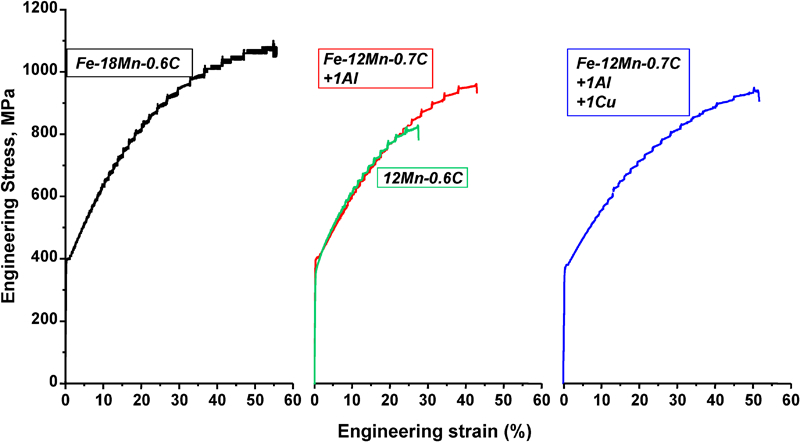
Stress–strain curves illustrating the effect of the reduction of Mn content of TWIP steel and the improvement of mechanical properties by minor additions of C, Al and Cu
Strain induced twinning
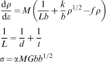
In a metastable austenitic steel, the deformation selection rules can in principle be controlled by the SFE, the martensite transformations in the alloy system (Ms,  and Md), the critical resolved shear stress for each deformation mode, the stress level and the strain path. The SFE is an important parameter, but it cannot by itself predict the plasticity mechanisms. Even in TWIP steel, mechanical twinning only takes place if strict conditions related to the grain orientation, the stress direction (i.e. tension or compression), the amount of deformation, the SFE and the temperature are met. The transition from slip only deformation to slip and twinning deformation occurs when the slip stress reaches the twinning stress. As there is no agreed model for twin formation, the stress required to nucleate a twin is difficult to compute without making some essential simplifications. The growth of a twin usually requires a much lower stress than what is usually computed by models, and it is therefore assumed that the high nucleating stress is due to a local stress concentration, as the applied stress results in homogeneous stresses too low to nucleate twins. The twinning stress increases with increasing SFE, and the stress required to nucleate a twin is related to the intrinsic SFE in a quadratic or linear manner. Various critical twinning stress formulas have been proposed and they are listed in Table 2, together with critical shear stress values for an SFE of 20 mJ m−2.51–55
Critical stress for twinning (SFE = 20 mJ m−2, G = 60 GPa, b = 0·257 nm, bp = 0·148 nm, d = 20 μm, mean twin width L0 = 50 nm, K = 6 GPa, M = 3·06)
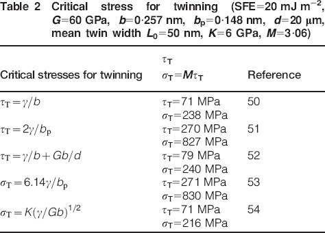
The grain size D plays a role in the value of the twinning stress and larger grains tend to expand the twinning domain53
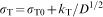
In TWIP steel, the nucleation of twins is not a homogeneous process: in the nucleation stage the formation of twins is closely related to prior dislocation activity, and strain induced twin formation occurs only after some amount of prior dislocation generation and dislocation–dislocation interactions. Twins are initiated in special dislocation configurations created by these interactions generally resulting in multilayer stacking faults which can act as twin nuclei. Three types of strain induced twinning nucleation mechanisms have been proposed: pole mechanisms, glide dislocation sources and cross-slip mechanisms. A number of these mechanisms are illustrated in Fig. 12. In the pole mechanism proposed by Venables,56–58 a jog is created on a dislocation by dislocation intersection (Fig. 12a). This jog dissociates in a sessile Frank partial dislocation and a Shockley partial dislocation. When the partial dislocation moves under the influence of an externally applied force, it trails an ISF and it rotates repeatedly around the pole dislocations, generating a twin in the process.
Schematic showing different stages in process of mechanical twin formation for a Venables pole mechanism, b Pirouz cross-slip mechanism and glide source mechanisms according to c Vergnol and d Mahajan
Glide type deformation induced twinning mechanisms have also been proposed. Glide sources are less probable sources of twins, but Bracke et al.,59 who studied twinning in Fe–22Mn–0·5C TWIP steel by means of TEM, found support for the Mahajan and Chin60 model for the creation of a three layer stacking fault acting as twin embryos (Fig. 12b). These twin embryos are formed by the interaction between two coplanar glide dislocations. The interaction leads to the formation of an ESF configuration. Larger twins form by the growth of twin embryos into each other.
In the cross-slip models for twinning,61–65 a twinning partial is formed by a double cross-slip mechanism (Fig. 12c) or by the interaction of a primary dislocation with a Frank dipole, a faulted dipole or a Lomer–Cottrell lock (Fig. 12d).
Although mechanical twins could in principle be nucleated at dislocations, grain boundaries or other pre-existing defects, it appears that some predeformation, considerable dislocation interactions and the nucleation of ESFs are always required to nucleate twins.
Grain orientation and crystallographic texture in general, can also have a pronounced effect on twinning. For example, whereas 〈100〉 oriented grains deformed in tension do not twin, grains oriented with a 〈111〉 type axis parallel to the tensile axis are heavily twinned.53,66
Press forming properties
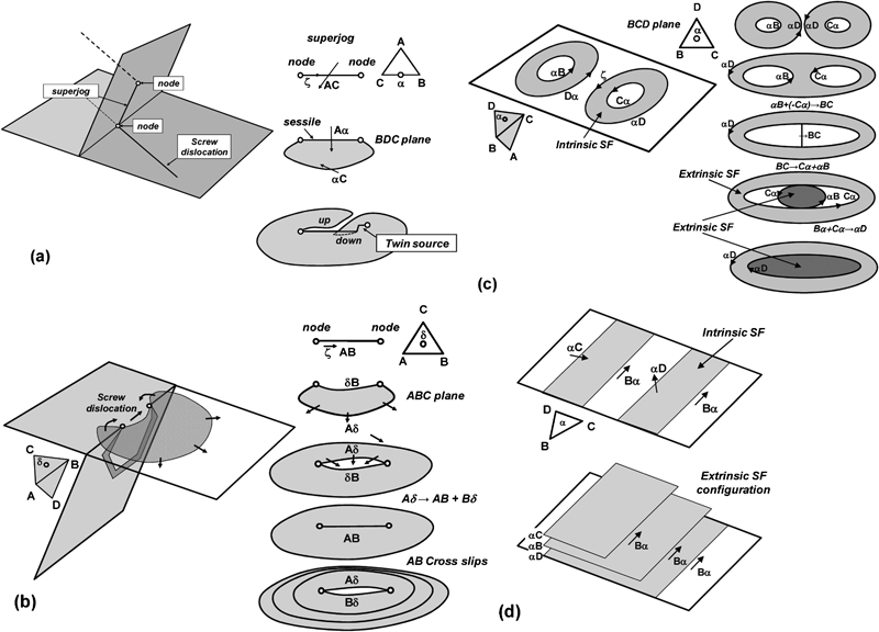
Compared to a uniaxial tensile test, deformation in press forming can be very complicated, involving complex and inhomogeneous conditions of strain and stress. The yield surface is often needed for numerical simulations and the shape of the yield surface is known to have a significant effect on the forming limit of anisotropic sheet metals. Figure 13 shows phenomenological yield functions for 1 GPa TWIP steel. In addition, typical values for the angular dependence of the normal anisotropy are listed.40 The planar anisotropy of TWIP steel is limited.
Yield surfaces for 980 MPa Fe–Mn–Al–C TWIP steel
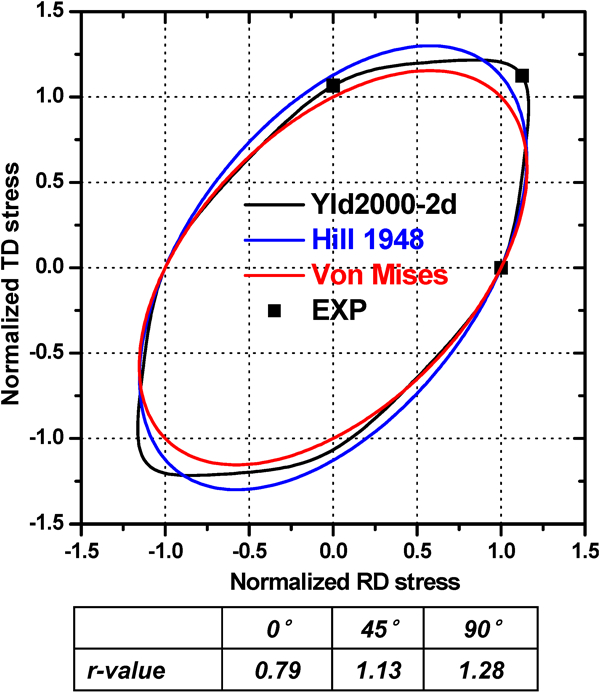
In sheet forming, the forming limit diagram (FLD) is obtained by determining experimentally the strains at which necking occurs for different deformation paths. Figure 14 compares the FLD of TWIP, IF, low C Extra Deep Drawing Quality (EDDQ) and TRIP steels currently used for automotive BIW applications. The necking strain in the plane strain deformation mode, the Forming Limit Curve Minimum (FLC0) value of TWIP steel is very high (45) compared to those for 590 MPa dual phase steel (30) and 780 MPa TRIP steel (28). The press forming properties of TWIP steel have therefore proven to be excellent as illustrated by the example of the shock absorber housing in Fig. 15. This makes TWIP steel ideally suited for the press forming of high strength parts with a complex shape.
Comparison of FLD curve of IF, EDDQ, TRIP and TWIP steel
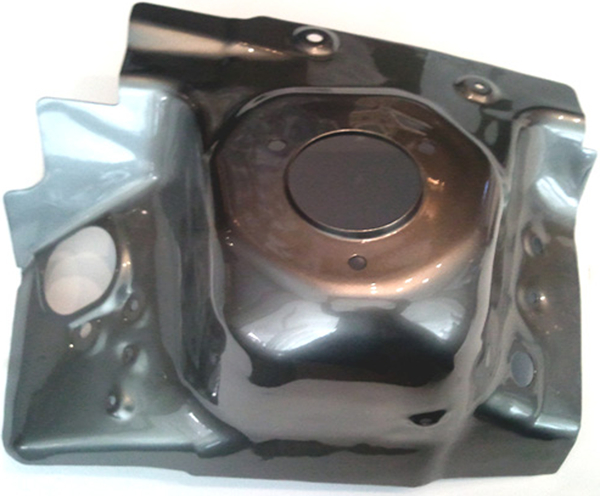
Example illustrating use of TWIP steel for press forming of a shock absorber housing
The stretch flanging properties of TWIP steel, typically evaluated by means of a hole expansion test, are considerably better than those of the other AHSS of a similar strength level, but not as good as those of ferritic deep drawing steel grades. The combination of low normal anisotropy and low strain rate sensitivity results in lower hole expansion ratios. This is very pronounced when a less appropriate hole edge preparation procedure leading to considerable hole edge deformation, such as in the case of hole punching, is used.67 This is illustrated in Fig. 16.
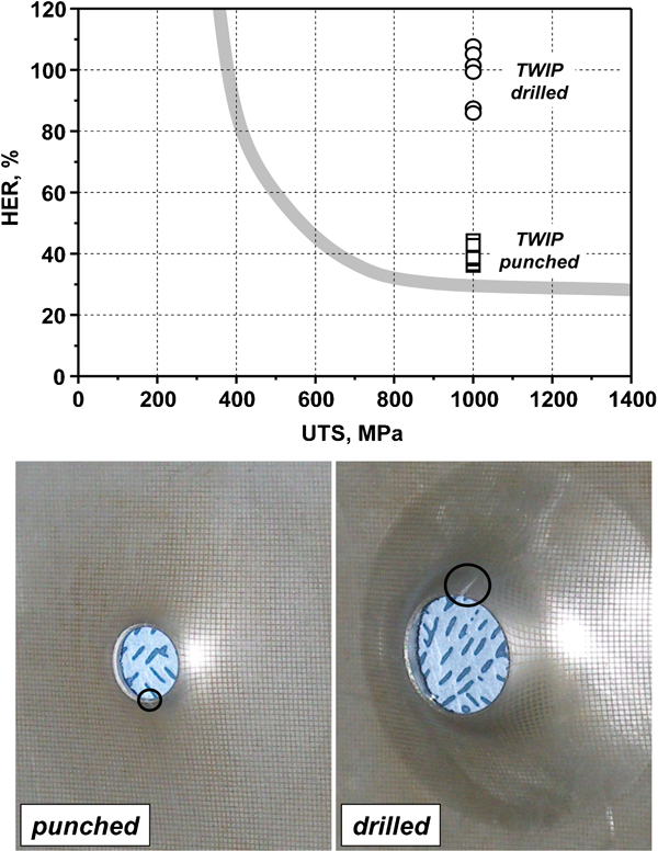
Hole Expansion Ratio (HER) for TWIP steel compared to the HER–ultimate tensile strength relationship observed for a large number of automotive materials indicated by grey band (top). Illustration of the difference in TWIP steel hole expansion performance for a low quality punched hole (below, left) and a high quality drilled hole (below, right)
High strain rate properties
The dynamic energy absorption of different types of automotive steels when tested at a strain rate of 102 s−1 are compared in Fig. 17. Frommeyer et al.3 have reported high strain rate properties for Fe–25Mn–3Si–3Al–0·03C TWIP steel. Extensive twinning was reported to occur during high strain rate deformation, and no brittle fracture was observed even at low temperatures. Ueji et al.68 studied the high strain rate deformation of Fe–31Mn–3Si–3Al TWIP steel for a grain size in the range 1·1–35·5 μm. In contrast to ferritic steels, there was still a large elongation at small grain sizes. Sahu et al.69 have studied the high strain rate behaviour of two Fe–24Mn–0·5Si–(0·11–0·14)C TWIP steels with 0·91 and 3·5Al additions. The transformation of austenite to martensite was reported to take place up to a strain rate of 103 s−1. TWIP steel alloyed with 3·5Al had higher stability, and the transformation of this TWIP steel was limited to the strain rate range 10−3–720 s−1. Irrespective of the Al content, the transformation of the austenite phase is suppressed during high strain rate deformations due to the adiabatic heating of the sample. Based on the observation of serrated grain boundaries, they also argued that dynamic recrystallisation may be taking place during the high strain rate tests.
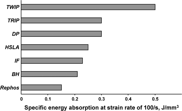
Comparison of energy absorption in J mm−3, during high strain deformation (strain rate: 103 s−1) for TWIP steel and common types of automotive steels
Strain localisation and point defects in TWIP steel
Dynamic strain aging occurs at room temperature in Fe–22Mn–0·6C and Fe–18Mn–0·6C TWIP steel. This phenomenon manifests itself as serrations in the stress–strain curve. During DSA, the mechanical deformation of TWIP steel is entirely localised in deformation bands which cross the tensile testing sample. The properties of these bands are illustrated in Fig. 18, which shows the hopping of the strain state at two points in the tensile sample during the motion of these Portevin–Lechatelier (PLC) bands. The properties of the PLC bands have been analysed in detail.70–72 The band velocity decreases with strain and the band strain rate is 15–100 times the applied value. Localisation may in principle result in press forming difficulties, but the occurrence of PLC bands in uniaxial tensile testing has not been reported to lead to the poor press forming performance for TWIP steel in practice. This is very likely due to the relatively high strain rates used in press forming. Other aspects of DSA should, however, not be overlooked. Dynamic strain aging results in negative strain rate sensitivity and it is the cause of a limited post-uniform elongation.
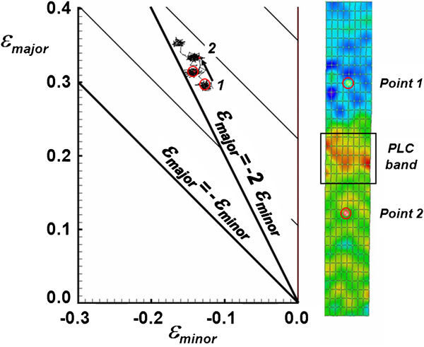
Dynamic strain aging in TWIP steel: type A serrations on the stress–strain curve of C alloyed TWIP steel are associated with the propagation of isolated PLC bands. Local strain analysis (left) shows that the sample deformation is entirely by the propagation of PLC bands (right), which are visible by infrared thermography
In C alloyed fcc alloys, the room temperature DSA cannot be explained by long range diffusion of C. Instead, it results from the short range order due to the presence of point defect complexes which can re-orient themselves in the stress field of dislocations or in the stacking faults. Possible defect complexes in TWIP steels are the following: C–vacancy complex, C–C complex and C–Mn complex. The most likely complex has one C atom in an octahedral interstice and one Mn atom. Direct evidence for the presence of these point defect complexes, and their interaction with dislocations, comes from internal friction measurements (Fig. 19). The DSA mechanism is similar to the one proposed by Curtin et al.73 The re-orientation of the point defect complex does not require long range diffusion, and only a single diffusional hop of the interstitial C in the complex is needed to achieve a suitable orientation with respect to the strain field of the partial dislocation or the stacking fault.
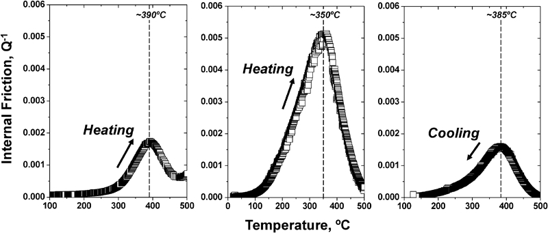
Internal friction measurement showing the presence of a damping peak associated with point defect complexes involving C in TWIP steel (left). The increase in the internal friction peak amplitude after straining is indicative of the interaction between the dislocations and the point defect complexes (middle). Annealing restores the peak amplitude measured before deformation (right)
Dynamic strain aging and the associated serrated stress–strain curves can be avoided by addition of Al as illustrated in Fig. 20. As Al increases the stacking fault energy, but does not interact with the point defect complex and decreases the C diffusivity in TWIP steels, the data clearly suggest that the interaction giving rise to the flow localisation is the interaction between the C–Mn point defect complexes and the stacking faults. The study of fundamental aspects of DSA is ideally suited for analysis by ab initio modelling. Mn rich octahedra are preferred locations for C atoms. The probability of a pure Mn octahedron is low. The Mn–C bond is stronger than the Fe–C bond. Preliminary results show that the Fe–Fe and Mn–Mn bonds are influenced differently by the presence of C. In the presence of C, the Fe–Fe bond strength is slightly destabilised and the Fe–Fe bond length becomes slightly longer. In contrast, the Mn–Mn bond length is reduced. This leads to the stabilisation of C containing Mn rich octahedra, and hence short range ordering.74,75
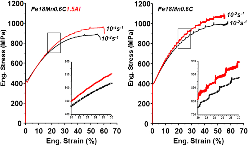
Stress–strain curves of TWIP steel illustrating suppression of serrations due to DSA by Al additions
Delayed fracture
The delayed fracture phenomenon is illustrated in Fig. 21. It was originally identified as a major problem in Fe–22Mn–0·6C TWIP steel, where the effect appears in fully deep drawn cups a relatively short time after cup drawing. Note that high residual tensile hoop stresses are known to be present in the edge of fully drawn cups. Kim et al.76 have suggested that it is related to martensitic transformation in the presence of residual stresses and hydrogen. They investigated the influence of martensite formed during the deformation of Fe–18Mn–0·6C and Fe–18Mn–0·6C–1·5Al TWIP steel. Al added TWIP steel was free of martensite after tensile testing, but both types of TWIP steel contained martensite after cup drawing. The amount of the embrittling martensite phase was lower in the Al added TWIP steel.
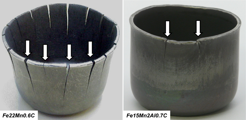
Example of delayed fracture deep drawn Fe–22Mn–0·6C TWIP steel (left) and suppression of delayed fracture in deep drawn Fe–15Mn–0·6C TWIP steel by alloying additions of 2·5Al (right)
Jung et al.77 compared the hydrogen embrittlement of TRIP and TWIP steels after cathodic hydrogen charging. They report that Fe–15Mn–0·45C–1Al and Fe–18Mn–0·6C TWIP steels, with and without Al additions, contained less hydrogen and were much more resistant to embrittlement than TRIP steel after U bend and cup drawing tests.
The delayed fracture issue has prompted interest in testing the sensitivity of TWIP steel to hydrogen induced embrittlement.78 The absence of any noticeable degradation of the mechanical properties after H charging, except for a relatively small reduction of the total elongation, suggests that TWIP steel may actually be insensitive to hydrogen induced fracture (Fig. 22). Delayed fracture in TWIP steel is therefore very likely a form of stress corrosion cracking as three conditions must apparently be satisfied simultaneously: high residual stresses, presence of a strong hydrogen trap site and hydrogen absoption. If any of these conditions is not satisfied, delayed fracture is unlikely to occur.
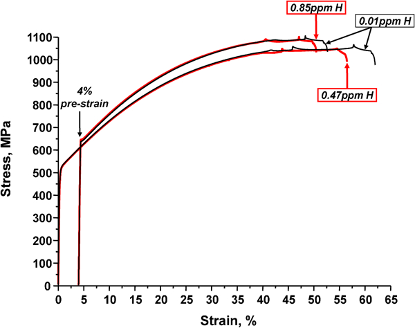
Influence of cathodic hydrogen charging on stress–strain curve of Fe–18Mn–1·5Al–0·6C TWIP steel: low current density hydrogen charging was carried out at 40°C for 24 h
Fatigue properties
In the as received state, TWIP steels experience cyclic softening during fatigue testing. During cyclic tests the dislocation density decreases and the existing twins become wider. The resulting lack of dislocation–twin interactions and the absence of nucleation of new twins are the major causes of the observed softening. Predeformation has a positive effect on the fatigue life of Fe–22Mn–0·52C TWIP steel,79 as the presence of twins formed during predeformation leads to a stable response in cyclic loading and a longer fatigue life. High cycle bending fatigue results for Fe–22·3Mn–0·6C, Fe–17·8Mn–0·6C and Fe–16·4Mn–0·29C–1·54Al have been reported by Hamada et al.80 The steels had a 2×10⁶ cycles fatigue stress limit of 400 MPa which was well above the yield stress. The ratio of fatigue limit to tensile strength was comparable to the ratio for austenitic steels, 0·42–0·48.
Welding
Resistance spot welding (RSW) is the most important joining method for automotive sheet steel. The RSW of TWIP steel is more challenging than the RSW of plain C steels, and special precautions need to be taken when welding TWIP steels to standard low C grades. As TWIP steel has a fully austenitic microstructure, care must be taken to avoid solidification cracks in the welds. TWIP steel has a smaller welding current range, and the weld expulsion occurs at lower welding currents. In addition, the weld nugget is lower in hardness than the base metal hardness. Common TWIP steel weld defects included grain boundary liquation crack in the heat affected zone and void formation.81 Welding TWIP steel to conventional C steel may result in inhomogeneous temperature profiles and weld nugget properties as the thermal (e.g. electrical resistivity) and physical (e.g. melting temperature) properties of the two materials may be significantly different.
Al addition also decreases the welding current range of TWIP steel, but new welding conditions have been proposed recently.
Ultra fine grained TWIP steel
Ultra fine grained austenitic Fe–31Mn–3Al–3Si TWIP steel has considerable ductility in contrast to ultra fine grained Al or IF steel.82,83 Nanostructured Fe–22Mn–0·6C TWIP steel, obtained by a combination of cold deformation and recovery annealing, has been reported to have a very high yield strength and an adequate elongation.84 The material preparation process decreases the dislocation density and retains the very dense nanoscale twin microstructure.
Industrialisation of TWIP steel
The considerable interest in high Mn TWIP steels is due to their superior mechanical properties. Compared to conventional low C steels, high Mn TWIP steels have high C and Mn contents. When Al is added, the content also tends to be high. It is clear that the cost issue, partly related to the alloy cost, will be of prime importance in addition to the remaining technical problems related to the manufacturing of TWIP steels. In early 1990s, the industrial production of high Mn TWIP sheet steel faced a large array of technical difficulties. However, the South Korean integrated steel producer POSCO85 has recently shown that high Mn TWIP sheet steel could be produced in conventional steel strip production facilities which usually process ferritic low C sheet steel, if some key precautions and working methods are used. This achievement is illustrated with the schematic flowchart shown in Fig. 23, which is used to produce industrially TWIP steel. One of the challenges is the ferromanganese alloy required for the steelmaking process. Standard ferromanganese has a high P content and is unsuitable for the production of quality TWIP sheet steel products. Ultra low P content ferromanganese alloys, with P contents of 0·05, have been developed for the production of TWIP steel.86 Steel plant practice also requires alternative working methods for the production of TWIP steel, such as the premelting of the ferromanganese additions before alloying, and the use of liquid rather than powder type fluxes during continuous casting to reduce the Al2O3 pickup, ensure edge quality and avoid cracks. The oxide scale formation during reheating should be controlled to avoid internal grain boundary oxidation which results in surface defects or edge crack of hot coil. The presence of Al in Fe–Mn–Al–C TWIP steel results in the formation of some limited amounts of (Fe,Mn)Al2O4 intergranular oxides and plate shaped hexagonal AlN precipitates during the slab reheating stage. No specific problems are encountered during hot rolling, coiling and pickling. Cold rolling reductions are slightly limited due to the high strain hardening behaviour of TWIP steels. During the recrystallisation annealing after cold rolling the recrystallisation takes 103 s at 560°C, and only 10 s at 630°C.
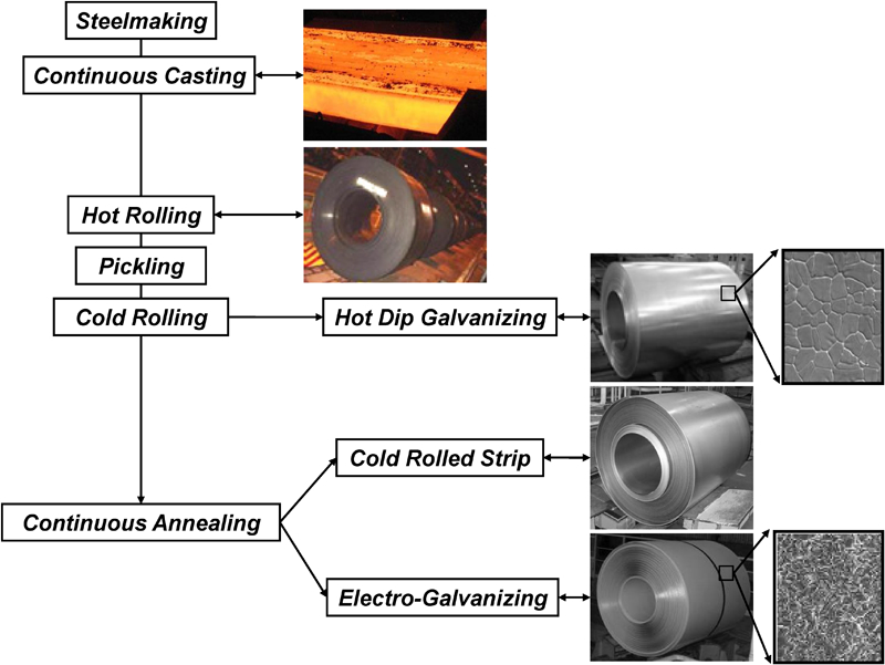
Schematic flowchart for industrial production of TWIP steel
The application of Zn and Zn alloy coatings by hot dip galvanising requires special care as there are clear indications that a MnO and Al2O3 surface layer is formed during continuous annealing and processing in a hot dip galvanising line. These MnO and Al2O3 surface layers will very likely influence coating adhesion, and electrolytic Zn deposition may be the preferred route for coating TWIP steel in certain cases. Both hot dip galvanising and electrolytic coating of TWIP steel have been attempted and defect free Zn coatings have been produced. The hot dip galvanising of TWIP steel requires the use of a very low dew point to avoid bare spot defects on the hot dip Zn coated sheet steel. If the dew point range is 0–20°C during the annealing process, a thick oxide layer will form on the strip surface and bare spot defects will present in the coating. Recent reports have shown that at a very low dew point, the bare steel is present between MnO selective oxide particles87,88 rather than a continuous MnO layer. Lowering the Mn content from 18 to 15, will also facilitate the hot dip coating with Zn.
Alternative Zn coating routes have been suggested. One approach is the ‘heat to coat’ method in which the pickled cold rolled strip is annealed a first time and repickled before a low temperature heat to coat galvanising process. The heat to coat process involves annealing in an initially oxidising gas atmosphere in a direct fired furnace heating section containing 1 vol.-O2. The reduction is carried out in the soaking section which contains a 15 vol.-H2 atmosphere. Successful heat to coat pilot tests have been reported for a Fe–15Mn–2·5Al–0·7C TWIP steel with <0·25 mass-Si.14
Conclusions
The present review of the properties of high Mn TWIP steel clearly shows that high Mn ferrous alloys with additions of C, Al and/or Si to fully stabilise the fcc phase and control the SFE within the narrow range of 20–50 mJ m−2, have a very wide range of mechanical properties, making this relatively new class of steel of interest for many automotive applications.
The physical metallurgy of TWIP steels is still relatively unexplored and the following aspects need to receive an in depth analysis: the twinning mechanism, texture evolution and delayed fracture. The determination of the twinned volume fraction remains a challenge and is needed to evaluate the different models proposed to explain the mechanical behaviour of TWIP steels. The distribution of the twinning as it is related to the formation of texture components must also be given a clear analysis. The precise mechanism of delayed fracture is still not known. In particular, the complex interaction of factors related to transformation, residual stresses and the influence of hydrogen, has made the issue particularly difficult to address. It is, however, clear that Al added TWIP steels may be considered immune to the problem.
Some fundamental aspects remain poorly understood, such as the precise nature of the relation between the strain induced twinning and the SFE. The relatively limited results based on ab initio calculations obtained up to now, have exposed the fact that random transition metal alloys with complex magnetic properties remain very challenging material systems for first principles modelling.
The technological progress has, however, been impressive, and it has been shown that TWIP steel can be processed successfully in existing industrial facilities.
Footnotes
Acknowledgements
This research was supported by WCU (World Class University) program through the National Research Foundation of Korea funded by the Ministry of Education, Science and Technology (grant no. R32-10147). The authors also gratefully acknowledge the help of Dr F. Barlat, Dr Yuri Estrin (Monash University, Australia), Dr Seok-Jae Lee, Dr Chen Lei, Dr Xu Le, Mr Jinkyung Kim and Mr Sangwon Lee.