
Abstract
The present article provides a technical survey of the effects of shot peening conditions on the fatigue performance of Ti–6Al–4V specimens representative of the material (and the surface treatment) used in helicopter rotor hubs. As the effects of shot peening on non-plain surfaces have been fairly neglected in the scientific literature, the present work attempts to define the effects of shot peening on different specimens, featuring specific cross-section geometries, namely smooth and sharp edged specimens. Experimental tests also include measurements of the residual stress field caused by shot peening and the definition of the fatigue limit (by means of the ‘staircase method’) for all the tested specimen configurations. The present study proceeds with an optical and scanning electron microscopic investigation of the dynamics and causes of the different fatigue limits associated with the geometrical features. The present study conveys a strong correlation between specimen geometry and shot peening microstructural effects, resulting in different fatigue performances. The present work concludes that, whenever surface treatment is involved in the manufacturing process, the component's design must be included, in addition to the required geometrical features for the operative conditions, an evaluation of how these provided features might affect the surface treatment outcome.
Introduction
The need for low weight and high fatigue resistant components has always been a crucial issue for the evolution of aircraft production. Scientific research has, thus, always struggled to keep up with the increasing demands of the aeronautic industry to design innovative materials, which are able to provide the required characteristics.
According to the aim previously stated, the present article studies the application of the Ti–6Al–4V alloy for the development of helicopter rotor hubs.1 This mechanical element is a widely employed design solution for helicopters and consists of a rotating structure in which the rotor blades are connected and constrained (in order to react mainly to centrifugal forces). According to the literature,2 a rotor hub is generally subjected to fatigue due to its rotation and the alternating stresses caused by the variable loads of the blades during rotation and by the interaction with the fluid (air). Thus, the design of the hub needs to take into account satisfactory fatigue resistance, which is usually achieved by the application of shot peening treatment to the hub. Shot peening is a mechanical surface treatment consisting of impacting at high speed a metal surface with thousands of small spheres. This treatment significantly increases the fatigue limit of the material by inducing a compressive residual stress field in the surface layer and by hardening the near surface layer. The impact of the spheres generates stresses that exceed, locally, the yield stress of the material and cause permanent deformation.3–5,20 This remains on the surface, and a residual stress field is generated in the component surface layer.6 However, even though shot peening is a widespread surface treatment, the literature contains few data concerning its effects on unsmooth shapes.7,8 Therefore, the present study investigates the fatigue resistance performance of peened surfaces featuring unsmooth geometrical shapes, which could be present in any type of mechanical component. The final aim is to verify how different specimen shapes, in particular sharp corners, can modify the effect of shot peening treatment on the surface layer and how this shape can consequently influence the overall fatigue performance. A particular focus has been dedicated to the study of the effects of shot peening on the microstructure of titanium alloy Ti–6Al–4V when the peened surface is other than plain.
During the experimental tests carried out to define the fatigue behaviour, a strong correlation between fatigue resistance and geometry of the previously peened surfaces has been observed. This experimental result is rather relevant since the current fatigue test standards do not specify the geometry of the specimen corners.9
Owing to the wealth of experimental fatigue data obtained in the present research, all the tabular data are presented in a normalised format. The normalisation factor is clearly highlighted in each table. Nevertheless, this kind of presentation clearly demonstrates the phenomena investigated and permits the appreciation of a large degree in which the surface structure affects the fatigue limits.
Experimental
The Ti–6Al–4V alloy is the ‘workhorse’ of the titanium industry, accounting for >50 of the total titanium usage. Ti–6Al–4V, grade 5, is an α+β alloy, containing ∼6Al and 4V. The Ti–6Al–4V considered in the present research is mill annealed, obtained from a plate of thickness 75 mm, orientation L–T. The chemical composition for the alloy is Ti–0·01N–0·001H–0·15Fe–0·16O–6·38Al–4·17V–0·01C (wt-), which is retrieved from spectrometric analysis.
The experimental work is structured in order to provide the correlation among shot peening, specimen shape/geometry and fatigue strength. Moreover, the alloy has been previously mechanically characterised by means of tensile tests in order to define the yield strength and the Young's modulus employed for the definition of the fatigue limit, according to the ‘staircase method’.10,11 The tensile tests are repeated a minimum of four times to obtain a reliable value for the material properties. The comparison of the experimental results with the data stated in the literature ensures satisfactory agreement (Table 1).
Mechanical characterisation of Ti–6Al–4V alloy and comparison of data retrieved from tests on site and provided by scientific literature

The specimens used for shot peening treatment have been previously electrochemically polished using a Struers Movipol device. This polishing treatment serves to remove the surface layer that is affected by residual stresses associated with the manufacturing process and that can alter the experimental results. The chemical composition of the specific polishing solution is acetic acid (94) and perchloric acid (6).
The shot peening treatment has been applied with two different Almen intensities, namely A6 and A12, which are directly related to the compressive stress field imposed onto the sample surface. Following the shot peening treatment, a series of residual stress measurements are carried out using an AST X-Stress 3000 X-ray diffractometer in order to assess the residual stress field obtained. Furthermore, the fatigue strength limit is defined using the staircase method.10,11 A set of 12 specimens are tested for each fatigue limit. An upper limit of 107 fatigue cycles is defined above which the specimen is considered to be runout. According to the standards, the fatigue limit is determined using the following relationship (equation (1))
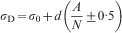
 .
.
The fatigue bending tests were carried out using a RUMUL CRACKTRONICS resonant testing machine; the kinematic conditions imposed by the testing machine allow pure bending cycles between the gripping heads. The load application frequency employed in the fatigue tests has been tailored according to the resonance frequency of the specimen machine system. The experimental investigations for the fatigue limits involve two different load ratios, i.e. R = −1 and R = 0·1 respectively (Fig. 1), in order to apply on the specimens fixed amplitude stress cycles. The former employs an average load equal to 0, meaning that the load curve is set symmetrically to the x axis, while the latter consists of a minimum load applied equal to 10 of the maximum load, as shown in Table 2.
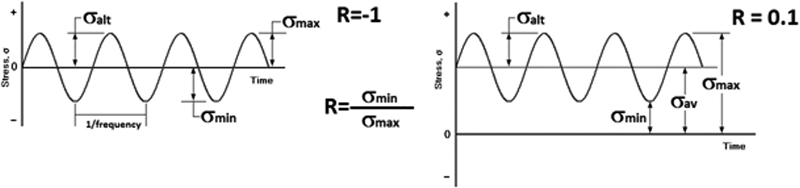
Schematic representation of fatigue cycles imposed during stair case test
Load conditions applied during fatigue tests for both R = −1 and R = 0·1 load ratios*
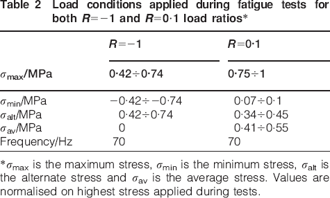
*σmax is the maximum stress, σmin is the minimum stress, σalt is the alternate stress and σav is the average stress. Values are normalised on highest stress applied during tests.
The specimen geometry employed during the present study is tailored to the specific test type, i.e. the shot peened smooth specimen requires a different design due to the very high loads needed to be applied for the higher stresses compared with the non-peened specimens. Moreover, the present study aims to investigate the relationship between the geometry of the specimen surface, the modification of the microstructure after shot peening and the associated fatigue resistance. Thus, the various specimen configurations employed are designed specifically for this purpose (Fig. 2) with a reduced central section and different edges. The sharp (acute) configuration is featured by right angled edges, while the smooth geometry shows two 45° angle blunt ended corners.
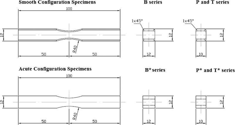
Technical drawings of fatigue specimens employed during experimental work
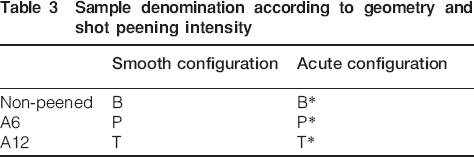
During the experimental work, the specimens that were not shot peened have been labelled as B series, while the P and T series refers for A6 and A12 Almen intensity respectively. The different geometries have been indicated by the asterisk symbol, i.e. B, T and P series for smooth specimens and B*, T* and P* series for sharp specimens, as reported in Table 3.
Sample denomination according to geometry and shot peening intensity
The two structural constituents have been developed by chemical microetchings: Kroll etching and oxalic based solutions. The former contains 1·5 mL of HF, 4 mL of NNO3 and 94 mL H2O, while the latter consists of 20 mL of HF, 20 g of oxalic acid and 98 mL of H2O. Both solutions are widely used in the microetching procedures for titanium, and their composition is provided by the scientific literature.14
Results and discussion
As previously stated, the experimental part of the present study consists of a thorough analysis of the fatigue performance of shot peened Ti–6Al–4V specimens of different geometrical configurations, namely acute and smooth. The residual stress on the surface of the non-shot peened specimens (B and B*) has been measured (Fig. 3) following an electropolishing procedure. The electropolishing procedure is designed to remove a very thin surface layer, thereby smoothing the surface and removing the surface stresses associated with the manufacturing process that the components might have undergone. The measurements are then repeated on the specimens following the peening treatment (T, P, T* and P*). The residual stress profiles for all the specimens are compared. In order to measure the residual stress profile versus the surface depth, the specimens have been submitted to additional consecutive electropolishing applications. Several electropolishing treatments with reduced intensity have been performed, and the residual stresses after each treatment have been analysed.
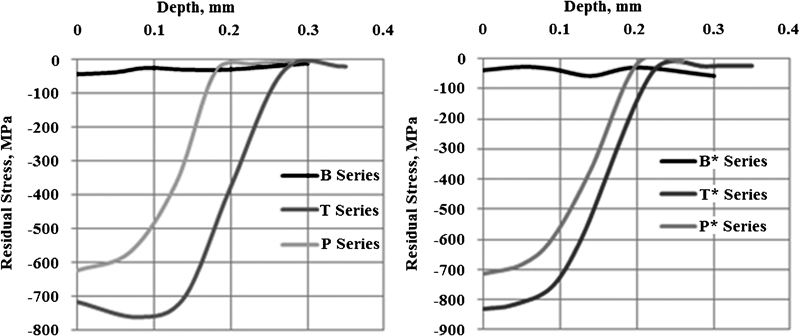
Residual stress profile versus depth for different configurations: smooth (right) and acute edged (left)
As expected, the shot peening confers a relevant compressive stress field to the material surface. This stress field decreases progressively with depth. Moreover, it has been observed that passing from A6 to A12 intensity results in an increase in the absolute value of the superficial compressive stresses and an increased depth in the hardened surface layer. The comparison of the profiles for smooth and sharp edges attests the presence of more intense residual stresses for both T* and P*, which may suggest a stronger deformation process occurring during shot peening.
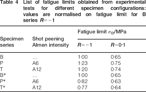
The present study then proceeds with the fatigue resistance tests (Table 4). As expected, shot peening treatment increases the fatigue performance of the smooth configuration specimens. Both A6 and A12 (T and P series) show, in fact, higher fatigue performance compared to the B series (reference value in Table 4), which were not shot peened. Contrary results were obtained for the acute configuration specimens (Table 4). Shot peened specimens exhibit a clear decrease in fatigue performance while featuring an acute edged geometry, P* and T* series. Parallel to this, the fatigue limit results obtained from the specimens that have not undergone shot peening (B and B*) show no significant difference in fatigue resistance among sharp and smooth specimens. These results suggest that in this case (smooth and acute configurations but non-shot peened), the influence of the corner geometry on the mechanical performance is moderate or at any rate inferior to the effect of shot peening on sharp corners. In other words, these data lead to the conclusion that the decrease in mechanical properties can be mainly attributed to the combination of shot peening and the presence of acute edges, rather than to the corner geometry alone.
List of fatigue limits obtained from experimental tests for different specimen configurations: values are normalised on fatigue limit for B series R = −1
In order to investigate this observed phenomenon more deeply, a series of microstructural investigations focusing on the critical areas of the shot peened specimens, i.e. the edges of the corners, have been carried out. The microstructural analysis of the material strained by shot peening shows a relevant morphology alteration of the grains close to the edges. The dimension of the grains decreases drastically, approaching the surface for both acute and smooth corners. According to the literature,15 such a deformation is caused by the high speed of the particles associated with the shot peening at impact with the surface (Fig. 4).15 Even though the observed deformations share some similarities, the microstructure of the acute and smooth configurations shows also strong differences. Actually, the grains on the sharp edges appear almost ‘squashed’ along the impact direction (indicated by red arrows), probably because of the more intensive shear deformation suffered by the surface (Fig. 4a–c). This large deformation is directly connected to the corner configuration: the collisions of the shot peened particles with the surface do not just result in hardening of the surface, but they also work towards smoothing the sharp edges, provoking an intense shear strain field. This assumption is verified by means of optical microscopy, which shows that the sharp ends of the corners are almost completely detached from the surface after shot peening.
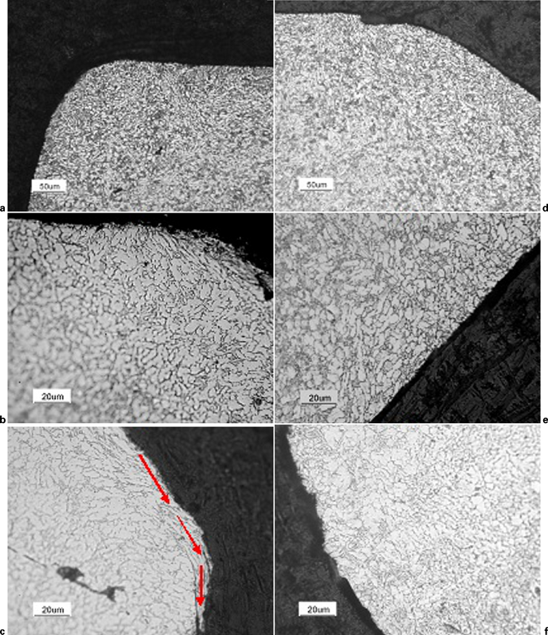
Microstructure images by means of optical microscopy at different magnifications
These phenomena indicate a more intense deformation affecting the surface along multiple directions. The presence of such mechanical deformation involves also a relevant stress field and the migration of dislocations to the grain boundaries. In other words, the grains on the acute corner surface undergo a much stronger hardening process than the grains of the rounded edges. According to the literature,16–19 the performance of the metal during a fatigue cycle is negatively affected by strong hardening, especially when a shear strain field is involved. It can, thus, safely be assumed that the acute geometry of the corner configuration is responsible for the lower fatigue associated with the specimens featuring sharp edges. In other words, as the material has already undergone intensive deformation, it is unable to dissipate more deformation energy, and thus, it cannot withstand the same number of fatigue cycles compared to standard specimens.
The electron microscopic fractography observations of the shot peened specimens (Fig. 5a and b) show that the cracks originate from the edge. They then propagate rapidly, causing the fracture and the removal of a part of the corner, regardless of the specific geometry considered. Such observations are consistent with the hypothesis stated previously regarding the detrimental influence of the microstructural changes induced on the corners. Corners are more sensitive to fatigue due to the higher intensity of the deformation suffered. The sharper the edge, the more detrimental the deformation induced and the easier the nucleation of a fatigue crack. The fracture on the edge (Fig. 5a and b) clearly appears to be brittle. It is typical of an alloy that is hardened and strained to such an extent that it cannot perform any further plastic deformation, allowing the dissipation of the applied mechanical work.
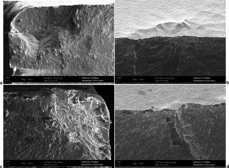
Scanning electron microscopy of fracture nucleation zone for a, b shot peened specimens and c, d non-shot peened specimens
On the contrary, the images of the non-peened specimens (Fig. 5c and d) do not indicate the corner as a preferable nucleation site for cracks. Instead, the fracture appears to originate from a pre-existent surface defect. The crack, then, proceeds in a ductile manner, as several dimples and other plastic deformation marks are evident on the surface fracture. Thus, it is significant to assume that the shot peening treatment, in the presence of an acute edged geometry, strongly affects the fracture dynamics, passing from a ductile fracture to a brittle fracture, localised on the edges.
Conclusions
The present study consists of a thorough analysis of the fatigue performance of the Ti–6Al–4V shot peened specimens featuring different geometrical configurations, namely fillet and rounded corners. The experimental work allows the comparison of the fatigue limits of different geometries. It further links the test results to the variations in microstructure, which result from the shot peening as a function of the shape of the corners (smooth and acute configurations) featuring the specimens. The experimental results lead to the following conclusions:
The use of an acute corner geometry combined with shot peening causes a decrease in fatigue resistance.
The previous observation is independent of the Almen intensity employed for shot peening.
The reasons for such a phenomenon are believed to be connected to the more distorted microstructure presented by the sharp edged specimens after the shot peening process.
The high speed collisions of the shot peened spheres with the sharp corners of the specimen cause not only desirable downsizing of the grains but also a high distortion of the microstructure.
The former sharp edged area appears to be more sensitive to fatigue and, as reported by SEM investigations, to be a nucleation point for cracks.
To conclude, the authors advise against the shot peening treatment of sharp edged components designed for fatigue resistant applications. As clearly shown in Table 4, the fatigue performance of these components (P* and T*) is lower compared to the untreated ones (B*). Therefore, the use of shot peening treatment on sharp edged components is counterproductive.