
Abstract
Coarse crystals of martensite can form by the coalescence of thin individual platelets of martensite under appropriate circumstances. Although these coarse grains are essentially single crystals, there exist significant orientation gradients across their dimensions. It is demonstrated that these gradients arise because of the plasticity induced in austenite due to the transformation strain associated with martensite growth. The resulting localised change in austenite orientation is then inherited by the new martensite growth, which consumes the deformed austenite.
Introduction
One of the attractive features of bainite or martensite is that the individual plates can be extremely thin, sometimes as thin as 20–40 nm in steels, which form bainite at temperatures <200°C.1–4 The thickness increases at higher transformation temperatures, typical of conventional alloys to ∼0·2 μm in normal bainitic steels.5–7
A fine structure is conducive to a good combination of strength and toughness, but it has been discovered that there are circumstances wherein adjacent platelets of bainite that share the same habit plane and variant of the orientation relationship with austenite tend to impinge and coalesce in the absence of intervening phases.8–12 The subject has been reviewed,13 and a typical micrograph of a coarse coalesced bainite plate is illustrated in Fig. 1; a three-dimensional characterisation using focused ion beam tomography has been reported.14 It has been demonstrated that eliminating this coarsening process results in significantly improved toughness.11–16
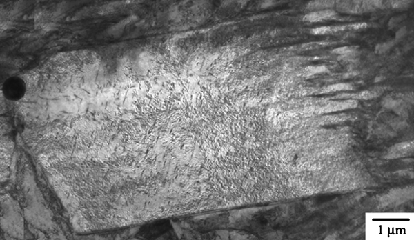
Coarse plate of coalesced bainite, many micrometres in thickness, forming by coalescence of finer platelets, which are visible towards right hand side11
As already stated, large plates, such as the one illustrated in Fig. 1, form as a consequence of the coalescence of finer platelets which are independently nucleated but share the same crystallography with the parent austenite. It has been shown, therefore, using electron back scatter diffraction, that large plates which are a consequence of coalescence are essentially single crystals but nevertheless contain orientation gradients of ∼0·3° μm–1.17 Considering the common characteristics involved in bainite and martensite growth,18 there is no reason to exclude the coalescence in martensitic structure once the large strain energy is available. The process has previously been described for isothermal martensite in an iron alloy.19 In the present work, therefore, the coalescence in martensitic structure was explored and explained, especially focusing on the origin of the orientation gradients.
Experimental
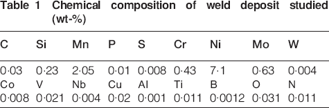
The alloy used is a weld metal described elsewhere in detail,20 but the chemical composition is given in Table 1, chosen because of the propensity of this alloy to form coalesced bainite. Following austenitisation at 950°C for 5 min, the sample was held at 385°C for 2000 s and then cooled continuously to obtain martensite.
Chemical composition of weld deposit studied (wt-)
Transmission electron microscopy was carried out on a sample prepared specifically from a grain of coalesced martensite using the focused ion beam technique, with the ion beam accelerating voltage reduced from 30 to 5 kV for the final delicate milling.
Dilatometry
The whole dilatometry curve, including isothermal processes, is presented in Fig. 2a. The isothermal transformation was performed in the region indicated by the arrow (Fig. 2b). It is evident that the bainite hardly formed and the subsequent quenching induced almost fully martensitic transformation. The martensite start temperature was measured as 337±2°C using the offset method,21 as shown in Fig. 3.
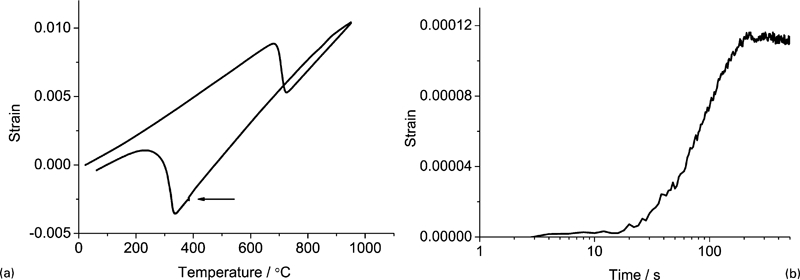
Dilatometry curve for a whole temperature range and b isothermal transformation at 385°C
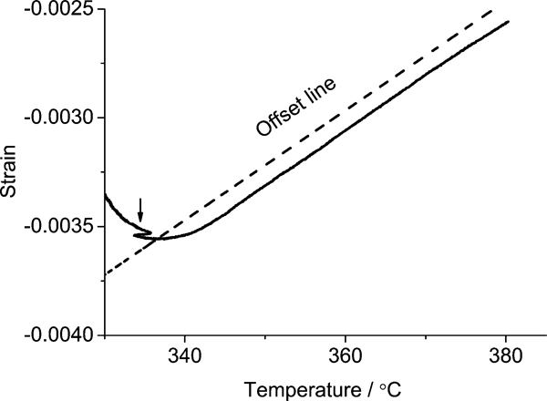
Illustration to find start temperature of martensite transformation following isothermal process: dotted line corresponds to offset line, and irregular curve indicated by arrow is due to unstable cooling in machine
Microscopy and diffraction
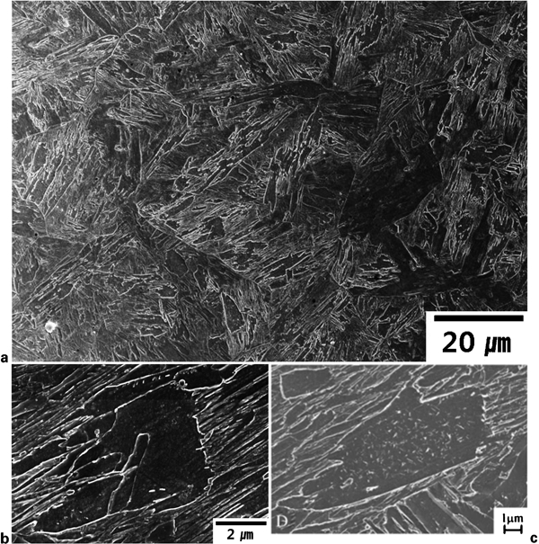
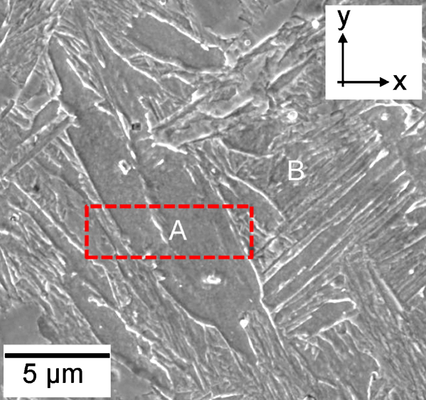
The martensitic structure produced from the dilatometric experiments consists of fine platelets and abnormally large structures (Fig. 4a), where the latter correspond to the typical coalesced structures (Fig. 4b and c).11 Figure 5 shows a large plate of coalesced martensite in the region marked a, surrounded by ordinary fine plates of martensite in the area designated b. Referring to the axes in Fig. 5, the plane of observation in the transmission electron microscope was x–z to ensure that the features observed correspond only to the coalesced structure. The transmission electron micrograph in Fig. 6 shows surprising detail, with evidence of the original platelets that integrated to form the coalesced plate in Fig. 5. The boundaries between the platelets are visible, indicating that there may have been small misorientations between the platelets before they coalesced.
Observation using scanning electron microscopy11
a coalesced and b fine martensite in focused ion beam micrograph: marked rectangle indicates area from which transmission electron microscopy sample was extracted
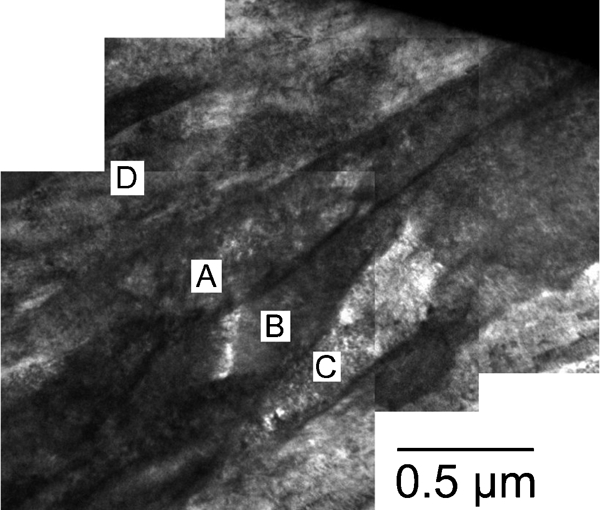
Transmission electron micrograph montage representing coalesced martensite illustrated in Fig. 5
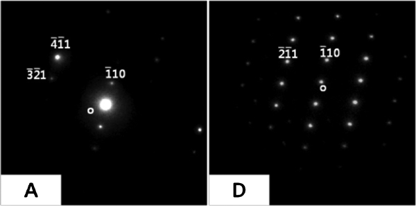
The electron diffraction patterns from ferrite platelets a, b and c, shown in Fig. 7, show that they are similarly oriented. However, the pattern from d could not be unambiguously indexed, so the sample was tilted to generate the pattern in Fig. 8; this indicated that the relationship between a and d could be described by a rotation of 9·4° about  , which is crystallographically equivalent to 180° about [0·650 0·054 0·758]
α
, where this axis is close to a diad, i.e. a small misorientaton. In other words, all the platelets a–d, which form the coalesced plate, have small relative misorientations.
, which is crystallographically equivalent to 180° about [0·650 0·054 0·758]
α
, where this axis is close to a diad, i.e. a small misorientaton. In other words, all the platelets a–d, which form the coalesced plate, have small relative misorientations.
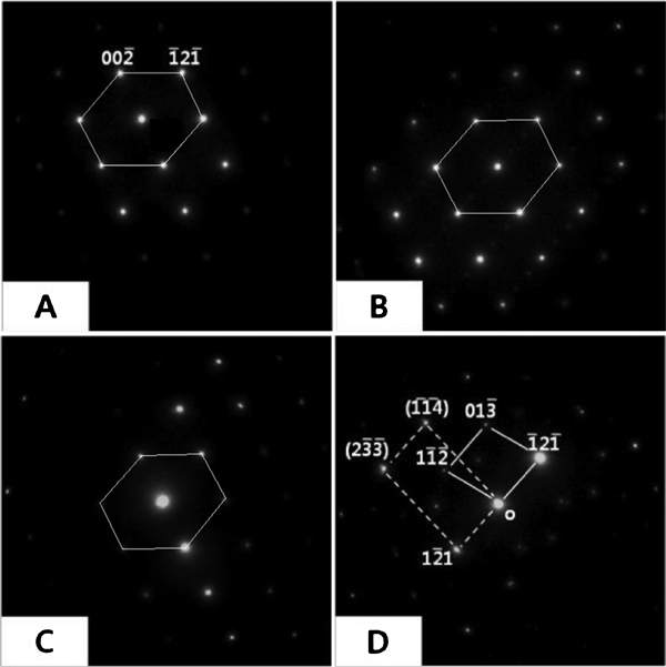
Diffraction patterns from each platelet marked in Fig. 6: A, B and C are similarly oriented but pattern from d is ambiguous
Mechanism for orientation gradients
The shape deformation during the formation of bainite is an invariant plane strain with a large shear component, a shear strain of ∼0·26 on the habit plane.22 A deformation like this is difficult to sustain elastically at the high temperatures where bainite forms, because the yield strength of austenite is low at elevated temperatures. Direct observations have shown that this accommodation occurs in a manner that compensates for the transformation shear.22 Transmission microscopy of samples in which some austenite is preserved following the growth of bainite has at the same time shown that the plastic accommodation creates a large dislocation density in the austenite beside the bainite.23 Two things should be noticed: first, plastic accommodation can also happen even during martensite transformation when austenite fails to accommodate the deformation fully elastically; and second, systematic plasticity of this kind may change the effective crystallographic orientation in the deformed region.24 In fact, Miyamoto et al.25 revealed that austenite beside a platelet of martensite as well as bainite has curved planes due to this very effect.
Therefore, a mechanism was proposed to induce small misorientations between plates, which, in a perfect crystal of austenite, would be in exactly the same crystallographic disposition in space. Edge dislocations present within the material only cause curvature of the lattice if there is an excess of positive or negative dislocations (extra half planes pointing above or below the slip plane respectively). Figure 9a illustrates the bending of glide planes caused by the presence of an excess density of edge dislocations with the same sign, the tilt being about an axis on the slip plane normal to the Burgers vector (of magnitude b). Suppose that the excess dislocation density localised into a region with width L (Fig. 9b); assuming a unit depth, the product ρL gives the number of dislocations per unit length and its inverse the spacing between the dislocations in the array which that the tilt boundary. It follows that for small misorientations, the misorientation θ about the line vector is given by

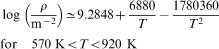
 so that b = 2·548 Å for a lattice parameter of aγ = 3·604 Å. The dimension L representing the deformed austenite beside the bainite plate is taken to be equal to the typical width of the plate, 0·2 μm. Here, ρ is the dislocation density. Dislocations in martensite and bainite formed at high temperatures are inherited from the austenite deformed to be compatible to the transformation strain, so the dislocation density in the product should be the same as that in the parent.26 The density ρ can therefore be estimated using an empirical equation available in the literature
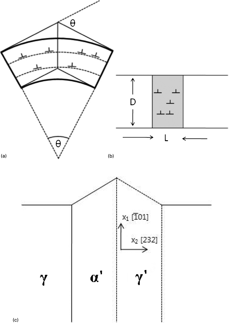
a dislocations causing development of misorientation in single crystal, b excess dislocations in grey area, assumed to align into column to cause constant misorientation between adjacent white areas and c plastic accommodation in austenite: region enclosed by dashed lines represents deformed austenite, upheaval being caused by shape deformation accompanying growth of martensite
Considering that the growth of martensite is identical to that of bainite crystallographically and that the plastic accommodation is allowed in austenite, the habit plane of martensite is assumed to be that given by Davenport27 as approximately (232)
γ
, as illustrated in Fig. 9. Austenite slips on the system consisting of close packed planes and directions  so that the slip direction approximately lies within the habit plane. Given that the habit plane is not a close packed plane of austenite, it requires a combination of slip systems to accommodate the transformation shear (we have neglected the smaller volume change due to transformation). Using the well established Taylor theory for the operation of multiple slip systems to account for an arbitrary plastic deformation,28 it was found that the simultaneous operation of the slip systems
  and
and  with the shear strain due to the former being five times that of the latter can accommodate the shape deformation of martensite. The full description for the calculation is available in Ref. 29.
We now proceed to estimate the rotation of the austenite lattice caused by this multiple slip, assuming the model illustrated in Fig. 9. Equation (2) gives the total dislocation density rather than the excess density, which is not known and will be a fraction φ of the total. Three values of the excess quantity were therefore tried, i.e. 0·25ρ, 0·5ρ and 0·75ρ, where ρ is the total dislocation density.
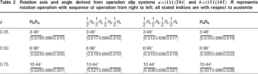
The rotation caused by multiple slip does depend on the order in which the slip systems operate, so four combinations of rotations were calculated, as listed in Table 2. The results show that the magnitudes of the rotations can be, as expected, small under appropriate excess density. It is interesting that the rotation axes listed are all approximately parallel to  , which corresponds to [101]α, given the orientation relationship between martensite and austenite. [101]
α
is of course the diad derived previously. Nevertheless, detailed comparison of the axis–angle pairs with observations is not possible because the specific crystallographic variants of the habit planes and shape deformations of the structure illustrated in Fig. 6 cannot be determined from the thin foil studies. Note also that it is not possible to compare the axis–angle pairs derived using the earlier electron diffraction data because they do not include information about the axis of rotation.
, which corresponds to [101]α, given the orientation relationship between martensite and austenite. [101]
α
is of course the diad derived previously. Nevertheless, detailed comparison of the axis–angle pairs with observations is not possible because the specific crystallographic variants of the habit planes and shape deformations of the structure illustrated in Fig. 6 cannot be determined from the thin foil studies. Note also that it is not possible to compare the axis–angle pairs derived using the earlier electron diffraction data because they do not include information about the axis of rotation.
Rotation axis and angle derived from operation slip systems and : R represents rotation operation with sequence of operation from right to left; all stated indices are with respect to austenite


Conclusions
It appears that the large plates which form by the coalescence of individual platelets of martensite retain vestiges of their origins because the boundaries of the original platelets are visible in transmission electron micrographs. This is because the platelets are not precisely identically oriented in space but have small relative rotations. These results are identical to those reported for the coalescence of bainite.
The rotations are explained on the basis that the shape deformation accompanying the formation of a martensite plate causes plastic strain in the adjacent austenite. This in turn changes the crystallographic orientation of the adjacent austenite, so that a new plate of martensite which grows from this deformed austenite will be slightly rotated relative to the original platelet.
An estimate of the degree of resulting rotation gives reasonable numbers, although it has not been possible to attain a quantitative comparison with experimental observations because such observations are incomplete due to the fine scale of the structure and because of the absence of austenite. A complete closure with theory would require the three-dimensional crystallography (habit plane, shape deformation and orientation relationship) to be characterised.
Footnotes
Acknowledgements
The authors are grateful to the technical staff at the NCNT-POSTECH for help with the TEM and FIB work, and to J. H. Kang and J. H. Ryu for discussions. The present work was funded by the Steel Innovation Program of POSCO and the World Class University under programme no. R32-2008-000-10147-0 of the National Research Foundation of Korea.