
Abstract
The evolution of morphological characteristics associated with creep induced cavities in a cast polycrystalline superalloy under various hot isostatic pressing conditions was investigated. Concentrically oriented N type γ′ rafting structures near the sintering cavities were formed during sintering. The stress gradient causing a chemical potential gradient around the cavity plays a dominant role in solute diffusion, resulting in the nucleation and continuous growth of the solid solution on the cavity surface to achieve healing.
Keywords
Introduction
Nickel based superalloys, strengthened through the precipitation of γ′ phase in the γ matrix, are widely used in gas turbine components such as blades and vanes, accounting for their excellent high temperature properties.1,2 The life of turbine blades is controlled by creep deformation and damage processes for the particular superalloy at elevated temperatures.3,4 The presence of creep induced cavities could greatly affect the mechanical properties of the blades. Nevertheless, hot isostatic pressing (HIP), a process to subject a workpiece to both elevated temperature and gas pressure simultaneously in an autoclave,5,6 has been demonstrated to be an effective method to eliminate such internal creep cavities that are deleterious to service life.
So far, the investigations into the cavity healing using HIP technology have been limited largely to the development of specific HIP processing schedules for rejuvenating various service exposed turbine components.5,7–9 However, very little research work has been carried out on the cavity evolution behaviour during HIP, and there is a lack of experimental validation on the corresponding healing mechanism. Some researchers have suggested that the process is analogous to that of the final stage of powder sintering, which is related to creep and diffusion, i.e. power law creep, grain boundary diffusion and lattice diffusion.5,10 Alternatively, the shrinkage process may be divided into sequential steps, including mechanical closure of the cavity, diffusion bonding and homogenisation.11,12 Accordingly, the purpose of the present work is to investigate the morphological evolution of creep induced cavities under various HIP conditions in order to identify the possible healing mechanism.
Experimental
The samples were removed from the mid-height section of a first stage aeroengine turbine blade where the temperature was the highest due to the gas flow. They were made from a cast polycrystalline superalloy K465, which has the chemical composition of Ni–0·15C–8·72Cr–9·87Co–10·31W–1·57Mo–1·03Nb–5·29Al–2·65Ti (wt-). One sample was sectioned and examined to reveal the degraded microstructure, while the others were subjected to three different HIP schedules in a laboratory HIP apparatus (ABB, Quintus). In the present study, the HIP treatments were carried out under an Ar gas pressure of 200 MPa for 4 h. The γ′ solvus temperature is 1230°C, and three soaking temperatures selected for HIP, i.e. 1180, 1230 and 1250°C, were designed to investigate the healing characteristics. In addition, it took only 30 min for the HIP unit to cool the samples from the applied high temperature and pressure to room temperature and 1 atm pressure. The hot isostatic pressed samples were sectioned to examine the morphological evolution of internal cavities since the cavities connected with the surface of the material could not be eliminated.
The samples were mechanically ground and polished with diamond paste. Casting porosities were examined by optical microscopy. The γ′ phase was then selectively etched in a solution of 10 g CuSO4, 50 mL HCl and 100 mL H2O. The microstructures were characterised with secondary electron image using a Hitachi S4800 FE-SEM.
Results and discussion
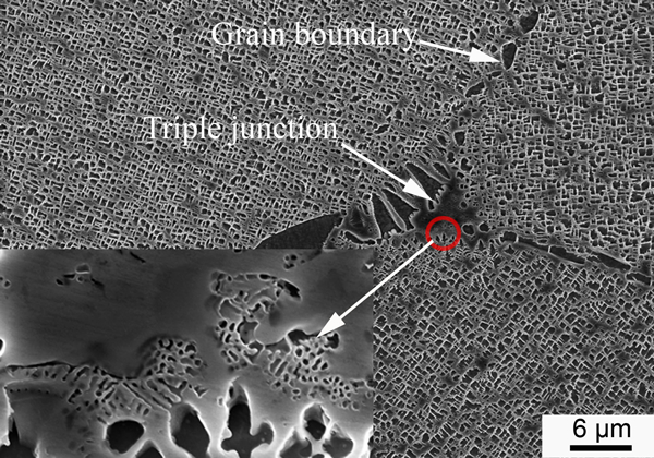
Figure 1 shows the degenerated microstructure of the blade aerofoil after 1200 h of service. In Fig. 1a, the large sized casting porosities formed during solidification were clearly seen on the as polished surface. The smaller sized creep induced cavities were found to be present both at the grain boundaries and in the grains. As shown in Fig. 1b, the creep cavity located at the triple junction continuously grew along the grain boundaries. Careful examination of the cavity at higher magnification shows that it possessed a relatively smooth surface with some degenerated carbides covering. These carbides were formed due to MC carbide decomposition during service exposure. In Fig. 1c, creep induced cavities can be observed in the grains. They were generally nucleated at the interface between the γ matrix and carbides due to stress concentration and carbide degeneration. In addition, the primary γ′ precipitates having the regular cubic morphology before service became blunt and coalesced, forming various shaped γ′ that were irregularly arranged.
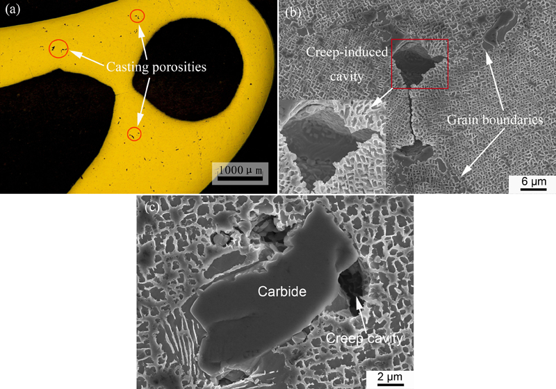
Microstructural features of degenerated turbine blade after 1200 h of service
In the hot isostatic pressed sample subjected to 1180°C/200 MPa/4 h, only a small quantity of casting porosities could be observed on the as polished surface, as shown in Fig. 2a. However, cavities of smaller size were still evident in the higher magnification SEM image in Fig. 2b. A particularly interesting phenomenon commonly found around creep cavities is presented in Fig. 2b and c, which ought to occur only when the HIP temperature is insufficiently high to dissolve the primary γ′ precipitates in large quantity. The γ′ precipitates near the sintering cavities were concentrically arranged and elongated perpendicular to the radial direction, whereas those remote from the cavities were irregularly arranged. Assume that the cavity in the sample under the applied hydrostatic pressure Ph can be simplified as a thick spherical shell model with internal radius Ri and external radius Re. In accordance with Lame's solution,13 the material deformed only along the radius due to its spherical symmetry and the effective stress σeff can be expressed by the radial component σr and the tangential component σ
θ
as follows13
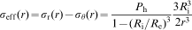
Morphological evolutions in vicinity of creep cavities under HIP condition of 1180°C/200 MPa/4 h showing a casting porosities in as polished surface, b, c concentrically arranged γ′ raft structure and d healing characteristics inside cavities
As observed in Fig. 2c, the dark regions representing two concentrically oriented γ′ rafts exhibited a relatively lower number density of primary γ′ than the bright regions, where the primary γ′ particles were irregularly arranged. Hence, it can be deduced that partial dissolution of γ′ precipitates proceeded at a higher rate due to the improved diffusion rates of solute atoms under equivalent tensile stress in the radial direction and the stress gradient.17 The sizes of these two raft structures were different, depending on the effective diffusion field, where obvious diffusion occurred during cavity healing. The stress gradient around the cavity surface, which was induced by the uniformly applied hydrostatic pressure, resulted in a chemical potential gradient causing solute diffusion. Meanwhile, the vacancies diffused in the direction opposite to that of atomic diffusion. The healing of the cavity is not influenced by the applied pressure when the cavity size is reduced to a critical value due to the inhibition of internal gas if possible.5 In Fig. 2d, an incompletely healed microstructure occurred at the centre of the cavity, while concentrically oriented γ′ rafts were formed around the cavity. Higher magnification of the boxed region indicates that the γ matrix was firstly nucleated on the cavity surface and grew continuously inward to fill the cavity.
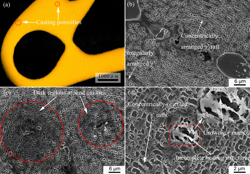
At 1230°C/200 MPa/4 h condition, where the primary γ′ was completely dissolved into the matrix, the sintering characteristics were also significant but without the raft structure. There was a distinct interface around the creep induced cavity shown in Fig. 3a. Inside the interface, the relatively smaller γ′ population reprecipitated in the newly formed matrix, and the opposite surfaces started to contact. It can be revealed from Fig. 3b that the γ matrix nucleated on the cavity surface and connected with the original matrix as a whole, while the γ′ particles newly precipitated during HIP cooling were selectively etched. A rough and wavy surface profile of the cavity was observed compared with the relatively smooth cavity surface in the pre-hot isostatic pressed sample shown in Fig. 1b.
Morphological characteristics of creep cavities in hot isostatic pressed sample subjected to 1230°C/4 h/200 MPa
In the hot isostatic pressed sample subjected to 1250°C/200 MPa/4 h, there was no evidence of obvious cavities, but some healing features can still be found at the triple junction in Fig. 4. The microstructure in the highlighted region consisted of extensive γ matrix and many small γ′ precipitates, and it was different with that of the grain boundary that contained large and discretely distributed γ′ after HIP. Compared with the creep cavity in Fig. 1b, it is probable that there had been a creep cavity formed at the triple junction after the long time service, and the cavity was nearly healed through bonding its surface together under HIP.
Morphological evolutions of creep cavities under HIP condition of 1250°C/200 MPa/4 h showing characteristics of healed cavity
Conclusions
Concentrically oriented N type γ′ rafting structures around the healing cavities were clearly observed only when the HIP temperature was insufficiently high to dissolve primary γ′ precipitates in large quantity. It appears that cavity healing under HIP is controlled by solute diffusion induced by stress gradient around the cavity, resulting in the nucleation and continuous growth of the solid solution on the cavity surface to achieve healing.
Footnotes
Acknowledgements
The financial support of the university–industry cooperation project (grant no. 201110026-01), sponsored by the Aviation Industry Corporation of China, is gratefully acknowledged.