
Abstract
Ni–43Ti–7Al (at-) alloy was directionally solidified at different withdrawal rates (2, 20 and 100 μm s−1) and a constant temperature of 1550°C by liquid metal cooling method. Results show that as the withdrawal rate decreases from 100 to 2 μm s−1, the cellular arm spacing increases from 39·5 to 126 μm, the size of Ti2Ni and the stability of the liquid/solid interface also increase, while the volume fraction of Ti2Ni decreases from 3·1 to 0·9. Moreover, microstructural analysis reveals that a NiTi+Ti2Ni anomalous eutectic structure is formed in intercellular regions of directionally solidified samples withdrawn at 20 and 100 μm s−1. However, in the sample withdrawn at 2 μm s−1, Ti2Ni phases represent strip and liquid droplet morphologies in the intercellular region. Finally, the possible explanation to the change of microstructure is discussed.
Introduction
NiTi based shape memory alloys with excellent shape memory effect and superelasticity have applications in various fields, such as mechanical electronics, medical implanting technology and automatic control systems.1,2 However, with the widespread development and application of NiTi based alloys, it is also more and more attractive as a potential high temperature structural material used in aerospace applications.3–6 As reported by Koizumi et al.,3,4 Al addition substituting for Ti could remarkably enhance the near equiatomic NiTi alloys at room and elevated temperatures (e.g. 800°C), especially when the Al content is high enough to precipitate the Ni2TiAl (β′) phase coherent to the NiTi (B2) matrix associated with proper heat treatment such as solution and aging. Later research found that the NiTi–Al based alloy could also be dramatically reinforced by the precipitation of Ti2Ni phase at room temperature,5–7 but some cracks were proved to form in brittle Ti2Ni particles and propagate on straight intergranular Ti2Ni paths; this would lead to the lower ductility of NiTi–Al based alloys.8 On the other hand, the melting temperature of Ti2Ni phase (984°C) is much lower than that of NiTi (1310°C) and Ni2TiAl (1513°C),9 so the high temperature (e.g. 800°C) mechanical properties of NiTi–Al alloys may be deteriorated due to the presence of Ti2Ni phases. Unfortunately, a small volume fraction of Ti2Ni could always be detected in NiTi and NiTi–Al alloys even at high Ni levels5,9,10 due to a small amount of oxygen in alloys.11,12 As we know, oxygen is introduced as impurities, in part through the raw materials. Moreover, unavoidable small scale leakage during melting will further increase the oxygen concentration. Therefore, oxygen can never be avoided, and it is difficult to eliminate Ti2Ni phase in the NiTi–Ni2TiAl alloy system. Further investigation is required to reduce the volume fraction of brittle Ti2Ni and meet the need of subsequent heat treatment to precipitate the Ni2TiAl phase.
Up to now, nearly all NiTi–Al alloys are melted using vacuum non-consumed arc furnace or vacuum induction furnace, which often leads to the non-uniform microstructure. In contrast to the above fabrication process, the directional solidification (DS) process can achieve precise microstructure control. Furthermore, the DS process can also eliminate transverse grain boundaries and prevent shrinkage cavities. However, little work has been published on the microstructure control of NiTi–Al alloys by the DS process.
In the present paper, the microstructural characteristics of directionally solidified Ni–43Ti–7Al alloys have been investigated. Results show that there exist considerable differences between the microstructures of directionally solidified samples withdrawn at low and high rates. Then, the possible explanation to the change of microstructure is discussed, which would be instructive to achieve microstructure control and provide a reference for optimising the microstructure and mechanical performances of NiTi–Al alloys.
Experimental
The nominal composition of the alloy used in the present study is Ni–43Ti–7Al (at.-). Master ingot (5 kg) was made from pure elements (99·76 wt-Ti sponge, 99·98 wt-Ni and 99·99 wt-Al) in a vacuum induction levitation melting furnace under argon atmosphere. After melting four times to promote the homogeneity of the alloy, the ingot was cast into a graphite mould. Then, the ingot was cut into bars with a diameter of 14 mm, which were used as master alloy bars for DS experiments. After grinding, cleaning and drying, the bars were enclosed in an Y2O3/Al2O3 double layer ceramic tube,13 which was 220 mm in length, 20 mm in outer diameter and 14 mm in inner diameter. The DS experiments were carried out in a vertical Bridgman furnace with W cylinder heating and liquid metal cooling. Before the DS experiments, the chamber of the furnace was evacuated at a 10−3 Pa level and backfilled with high purity argon to a pressure of 0·05 MPa. Then, the furnace was heated to 1550°C to melt the alloy. After holding for 20 min, the samples in the ceramic tubes were withdrawn at the rates of 2, 20 and 100 μm s−1 to ∼150 mm, followed by quenching into the Ga–In liquid metals to preserve the liquid/solid interface.
The DS samples were sectioned longitudinally and transversally by electrodischarge machining. After grinding and polishing, the microstructures and phase compositions were examined using a JXA 8100 type electron probe microanalyser (EPMA) equipped with energy dispersive spectroscopy (EDS). The volume fractions of Ti2Ni in the specimens were evaluated by quantitative image analysis on the basis of EPMA images using the software Image J 1·43u. The considered specimen area was large enough to ensure a representative statistic. An optical microscope (Olympus BX51M) was also employed to observe the quenched microstructures of directionally solidified samples, which were etched in a solution of 10HF+40HNO3+50H2O.
Results
Microstructures of as cast sample and directionally solidified samples
An EPMA photograph of the as cast microstructure is shown in Fig. 1, in which the equiaxed morphology can be found, and the microstructure is composed of two regions with grey and black contrasts. According to the EDS results in Table 1, the grey region represents the near equiatomic NiTi matrix phase (B2 phase), in which small amounts of Al are dissolved; the black one represents the Ti2Ni phase. Previous study indicated that the Ni–43Ti–7Al alloy could be regarded as a derivative of Ni50–Ti50 alloy,5,11 so the Ti2Ni phases will form within a peritectic reaction of L+NiTi→Ti2Ni according to the Ni–Ti equilibrium phase (Fig. 2).14 However, the Ti2Ni phases do not represent the morphology like other peritectic phases in the present study, but NiTi+Ti2Ni anomalous eutectic structures can be observed at grain boundaries, as shown in the lower left corner of Fig. 1.
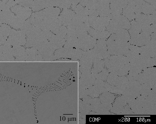
Microstructure of as cast alloy
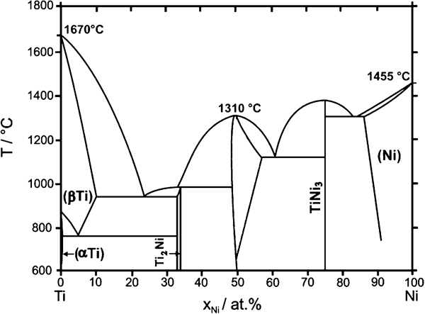
Ni–Ti equilibrium phase diagram
Compositions of constituent phases in as cast alloy and directionally solidified samples determined by EDS/at-
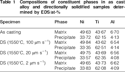
Figure 3 illustrates the steady state growth morphologies in the samples directionally solidified at different withdrawal rates (2, 20 and 100 μm s−1) and a constant temperature of 1550°C (left: longitudinal section, right: transverse section). It can be seen that the microstructures observed in the longitudinal sections of directionally solidified specimens are cellular structures replacing equiaxed grain structures of the as cast alloy. We can also observe two phases in these samples: the predominant grey NiTi phases accompanied by the black Ti2Ni phases distribute along the growth direction in intercellular regions. In addition, some Y2O3 particles (arrows) were dropped into the melt due to thermal convection and impaction during DS in the Y2O3/Al2O3 double layer ceramic tube.
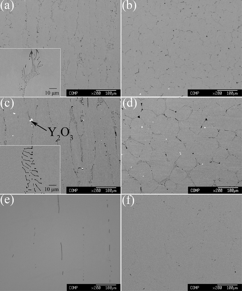
Typical steady state growth morphologies in samples directionally solidified at different withdrawal rates and constant temperature of 1550°C
As shown in Fig. 4, the cellular arm spacing increases from 39·5 to 126 μm as expected, while the volume fraction of Ti2Ni decreases from 3·1 to 0·9 as the withdrawal rate decreases from 100 to 2 μm s−1. Moreover, a NiTi+Ti2Ni anomalous eutectic structure is generated in the intercellular region of the sample withdrawn at 100 μm s−1, as shown in the lower left corner of Fig. 3a. A similar structure can also be found in the sample withdrawn at 20 μm s−1 (Fig. 3c), but the sizes of Ti2Ni and the eutectic spacing become larger. When the withdrawal rate decreases to 2 μm s−1, it is noticeable that the typical anomalous eutectic structure mentioned above may degenerate and cannot be observed. The Ti2Ni phases are predominantly of strip morphology along with the direction of heat flow, with a small amount of liquid droplet Ti2Ni phases observed in the intercellular region (Fig. 3e).
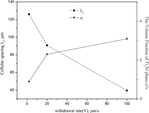
Withdrawal rate versus cellular spacing (λ1) and Ti2Ni volume fraction (α) in steady state region of directionally solidified samples
Solid/liquid interface morphology
Figure 5 shows the morphologies at the quenched solid/liquid interfaces of the directionally solidified samples withdraw at different rates. A few side branches are produced in the cellular structure at the quenched solid/liquid interface when the samples were solidified at withdrawal rates of 100 and 20 μm s−1, but the typical cellular interface can be found as the withdrawal rate decreases to 2 μm s−1. Obviously, the stability of the liquid/solid interface increases with decreasing withdrawal rate, according to the constitutional undercooling criterion.
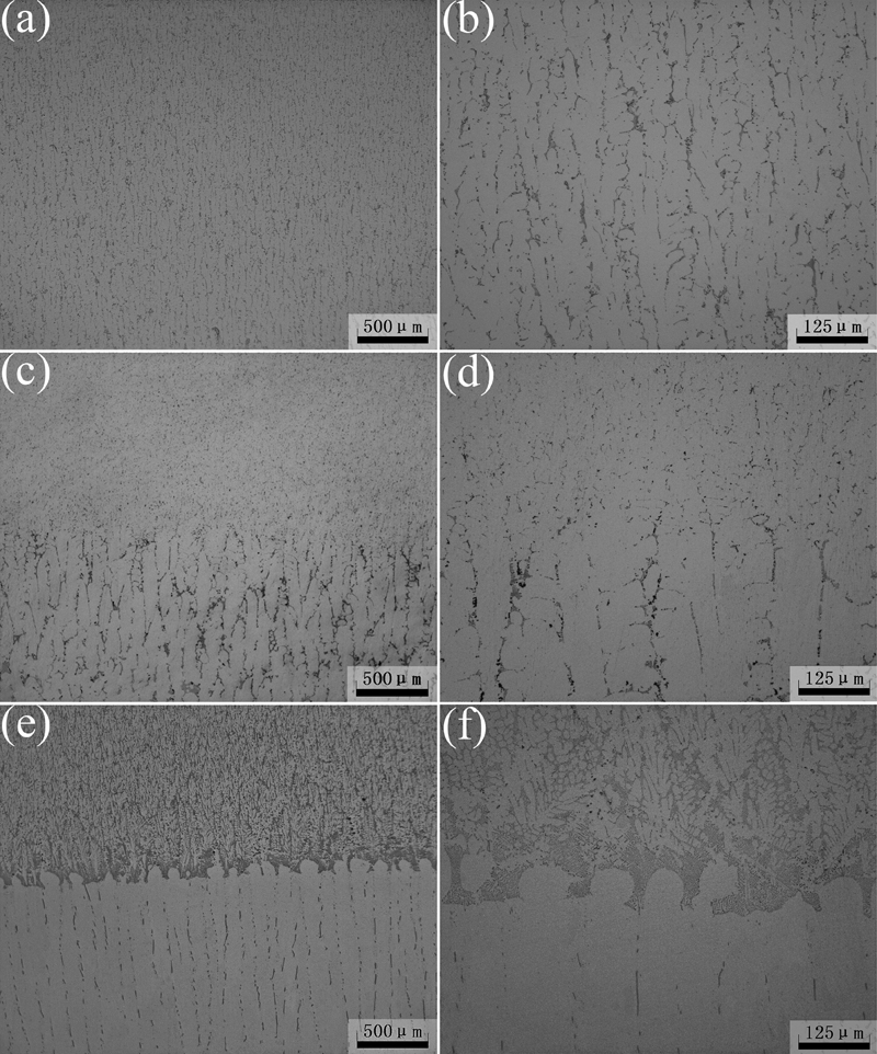
Morphologies at solid/liquid interfaces of samples quenched from steady state DS region at different withdrawal rates and constant heating temperature of 1550°C
Furthermore, the solidification pathway can be clearly distinguished by checking the microstructures of the high temperature phases persevered in the mushy zone on the longitudinal section of the quenched region. As shown in Fig. 5a, the mushy zone is not very clear when the sample was solidified at a high withdrawal rate of 100 μm s−1, but rather clear when the withdrawal rate decreases to 20 or 2 μm s−1 (Fig. 5c and e). As seen from the liquid/solid interface morphology, the NiTi phase is easily found to be the primary solidification phase in Ni–43Ti–7Al alloy, and the Ti2Ni phase is formed at the grain boundary of the prior NiTi phase during solidification.
In contrast to the steady state regions that have a difference in microstructure characteristic, the microstructures of quenched regions are all composed of primary NiTi phase and NiTi+Ti2Ni anomalous eutectic structure. Moreover, there are more Ti2Ni phases in the quenched region than the steady state region no matter how the withdrawal rate changes and the volume fraction of Ti2Ni in the quenched region increases with the decrease in withdrawal rate, as shown in Fig. 6.
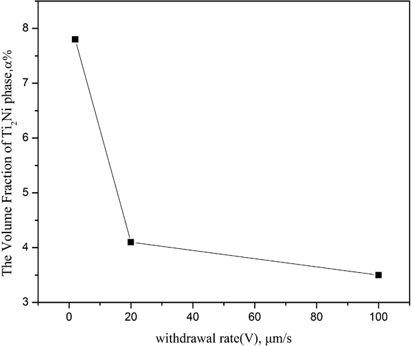
Withdrawal rate versus Ti2Ni volume fraction in quenched region of directionally solidified samples
Discussion
Previous works showed that oxygen could favour the formation of Ti2Ni phase, and the volume fraction of Ti2Ni would increase with increasing oxygen content.9,12 Later research indicated that oxygen could stabilise the Mackay icosahedra cluster, which is the fundamental cluster for the formation of Ti2Ni phase in undercooled alloy melts.15–17 Therefore, the Ti2Ni phase was considered to nucleate directly in the liquid phase due to the important role of oxygen,11 unlike most of the other peritectic phases that always nucleate on primary phases during solidification.
Considering the effect of oxygen on Ti2Ni phase, Table 2 shows the average oxygen contents of steady state and quenched regions in directionally solidified samples withdrawn at different rates respectively. It can be seen that there is a difference in oxygen content between steady state and quenched regions, and the difference becomes bigger when the withdrawal rate decreases. Especially in the sample withdrawn at 2 μm s−1, the average oxygen contents of steady state and quenched regions are 78 and 960 ppm respectively, with a ratio of nearly one in twelfth.
Average oxygen contents of steady state and quenched region in directionally solidified samples/ppm
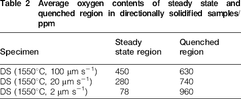
It is known that the maximum solubility of oxygen in the Ti2Ni phase is up to 14 at-, while it has an extremely low solubility in solid NiTi phase.9 Therefore, when the primary NiTi nucleates and grows during solidification, oxygen atoms will be rejected to the intercellular liquid, and the oxygen content in the intercellular region will increase with the progress of solidification. Because oxygen is much lighter than other elements in the present alloy, the oxygen enriched intercellular liquid has an average density lower than that of the liquid alloy above it. This density difference may cause the lower density liquid in the intercellular region to flow up to the top of the solid/liquid interface, and oxygen atoms within the lower density intercellular liquid will also flow, so the oxygen content of the steady state region will always be lower than that of the quenched region.
When the withdrawal rate is high, the depth of the mushy zone and the time for solute diffusion are expected to be relatively small. This will suppress the diffusion of oxygen between the bottom and top of the solid/liquid interface during DS and result in the small difference in oxygen content between steady state and quenched regions. Conversely, when the withdrawal rate is low, the depth of the mushy zone and the time for solute diffusion will be enough for more oxygen atoms to flow up to the top of the solid/liquid interface. As a result, the oxygen content of the quenched region in the sample withdrawn at low rate is higher than that of the sample withdrawn at a higher rate, finally causing the volume fraction of Ti2Ni in the quenched region to increase with decreasing withdrawal rate.
However, the oxygen content of the steady state region shows opposite change tendency in contrast to the quenched region. As shown in Table 2, the oxygen content of the steady state region in the sample withdrawn at 2 μm s−1 is much smaller than the other two samples withdrawn at higher rates. On the other hand, the number of icosahedral clusters is expected to decrease with decreasing cooling rate.18 Consequently, the nucleation of Ti2Ni phase will be impeded due to the less oxygen content and icosahedral clusters in the intercellular liquid with the decrease in withdrawal rate. Further consideration of the growth rate of Ti2Ni phase shows that the alloy composition demands significant partitioning and liquid diffusion for growth to proceed, so the growth rate of NiTi phase will be faster due to the requirement of little change in composition and high chemical driving force.19 Even though both of the two phases have more growth time with the decrease in withdrawal rate, the NiTi phase is expected to be more developed than the Ti2Ni phase. Thus, in steady state regions, the size of Ti2Ni becomes larger, whereas the volume fraction of Ti2Ni decreases with decreasing withdrawal rate based on the above analyses, which may make the present alloy meet the need of subsequent heat treatment to precipitate Ni2TiAl.
Additionally, based on the section on ‘Microstructures of as cast sample and directionally solidified samples’, Ti2Ni phases are found to form anomalous eutectic structures with NiTi phases in intercellular regions when the withdrawal rates are 100 and 20 μm s−1, but represent strip and liquid droplet morphology in the sample withdrawn at 2 μm s−1. In fact, NiTi+Ti2Ni anomalous eutectic structures can always be observed in near equiatomic NiTi alloys;7,20,21 however, the formation mechanism of this structure in the peritectic Ni–Ti system is still not very clear.
Generally, the peritectic phase nucleates on the primary phase, and then the primary phase will be covered by the peritectic phase in a peritectic system. However, when solidified at high rate, the peritectic phase will directly nucleate and grow in the liquid phase rather than nucleate on the primary phase, so the peritectic reaction will be suppressed.22–25 Moreover, according to the results of Hillert26 and Perepezko and Boettinger,27 there may be a transition from the peritectic phase diagram to a metastable eutectic phase diagram under non-equilibrium solidification condition. An essential mass transport mechanism like eutectic system for cooperative growth will be established in rapid solidification, so eutectic structures are normally observed in some peritectic systems due to non-equilibrium solidification,25–27 and NiTi+Ti2Ni anomalous eutectic structure could also be found in NiTi alloys fabricated by laser solid forming.21
However, the cooling rates in the above studies are all much larger than the present ones, which are not high at all and are not expected to entail a strong departure from local equilibrium at the interfaces. It is worth noting that a NiTi+Ti2Ni anomalous eutectic structure cannot be observed in the sample withdrawn at 2 μm s−1. Similarly, previous study suggested that adding yttrium to Ni–43Ti–7Al alloy would result in the formation of Y2O3 phase, and the anomalous eutectic structure could also not be observed.11 In both cases, the volume fraction of Ti2Ni is relatively small because the oxygen content in the alloy is much lower than that of the alloy, which contains NiTi+Ti2Ni anomalous eutectic structure. As we know, if the peritectic phase nucleates on the primary phase, the peritectic reaction may occur because of the junction of primary, liquid and peritectic phases, which will obviously impede the formation of the anomalous eutectic structure.
In the present study, because of a small amount of oxygen, the Ti2Ni phase may directly nucleate and grow in the liquid phase without rapid solidification rate,11 so the peritectic reaction is suppressed, and the Ti2Ni phase does not represent the morphology like other peritectic phases. On the other hand, oxygen atoms will be rejected to the intercellular liquid when the primary NiTi nucleates and then grows during solidification, which will favour the formation of Ti2Ni phase. Meanwhile, the average liquid composition at the interface of a Ti2Ni phase is larger in the Ni component, which may cause the formation of little Ni rich NiTi phase near Ti2Ni phase. That is, the thickness of the diffusion boundary layer may be remarkably reduced and an essential mass transport mechanism like the eutectic growth in which constituent atoms are exchanged between NiTi and Ti2Ni phases may be established. Therefore, the formation of an anomalous eutectic structure in the present alloy is also considered to be related with the oxygen content of alloys, and NiTi+Ti2Ni anomalous eutectic structure appears to be generated in the present alloy containing high oxygen content. However, because of the difficulty nucleation of Ti2Ni phase and the impeded diffusion of oxygen between the two phases, the volume fraction of Ti2Ni decreases, and the anomalous eutectic structure may degenerate with the decrease in oxygen content.
Conclusions
As the withdrawal rate decreases from 100 to 2 μm s−1, the cellular spacing of directionally solidified samples increases from 39·5 to 126 μm and the size of Ti2Ni also increases, while the volume fraction of Ti2Ni in the steady state region decreases from 3·1 to 0·9.
The stability of the solid/liquid interface is found to increase with the decrease in withdrawal rate. Moreover, in contrast to the steady state region, the volume fraction of Ti2Ni in the quenched region increases with decreasing withdrawal rate.
A NiTi+Ti2Ni anomalous eutectic structure can be observed in as cast sample and directionally solidified samples withdrawn at 100 and 20 μm s−1. However, in the sample withdrawn at 2 μm s−1, Ti2Ni phases represent predominantly a strip morphology, with a small amount of liquid droplet Ti2Ni phases observed in the intercellular region along with the direction of heat flow.
There is more oxygen in the quenched region than the steady state region, and the difference in oxygen content between them becomes bigger and bigger with the decrease in withdrawal rate, which causes the change in the volume fraction and morphology of Ti2Ni.