
Abstract
The relative performance of coatings for furan resin sand (FRS)–P-toluol sulphonic acid (PTSA) mould (FRS–PTSA), compared with no S, Novolak resin sand coated mould (NRS) was evaluated to determine the occurrence of a degenerated graphite surface layer. The FRS–PTSA moulds evidently incited graphite degeneration in the surface layer, as its thickness increased up to 10 times that with NRS moulds. Applying a mould coating containing S aggravated graphite degeneration. Conversely a desulphurising coating could protect the nodular graphite and limit the surface layer thickness. Independently of the S source at the metal/mould interface, sulphur affected graphite degeneration drastically. The coatings incorporating desulphurisation materials, [MgO; (CaO+MgO+Talc); Mg–FeSi] protected the iron from graphite degeneration, with the average layer thickness decreasing from 3·8 to 4·2: a factor of 7–10 reduction in FRS–PTSA moulds. If the first two coatings acted mainly as desulphurisers, the Mg–FeSi coating had an additional role to desulphurisation and provided Mg for the molten iron, to restore some nodularising potential. It is important to combine desulphurisation with supplementary Mg to remove migrating S and restore lost Mg. This complex behaviour could be realised by the application of coatings with active Mg from fine sized Mg–FeSi.
Keywords
Introduction
Chemically bonded sand moulds (self-set, no-bake and cold box) are commonly used for ductile iron castings production, especially those with large modulus, such as windmills (wind turbine) castings. Furan-acid and phenolic-acid no-bake systems are particularly attractive to ductile iron producers as these binder systems produce very strong, rigid moulds, and, consequently, lessen the risk of shrinkage. Although resin mould technology is popular in ductile iron casting production, it can contribute to graphite degeneration at the spheroidal graphite cast iron surface, as a flake (lamellar) graphite region.1–3 This abnormal surface layer can be present in different casting section thicknesses, but is most critical in thin wall castings, where it could be more than 10 of the total section. Heavy section castings are also prone to the effect due to the long solidification time providing a long metal–mould interaction time.
The formation of this abnormal structure in the surface layer in thin section ductile and compacted graphite irons, and its detrimental effects on the mechanical properties, was heavily documented in past years.4–10 Recent papers also reviewed the incidence of this defect in heavy section ductile iron castings, with direct reference to wind turbine casting quality.1–3 Generally, the surface degenerated graphite layer has a similar effect to a notch in the casting, reducing all the properties. The fatigue limit and impact resistance are both reduced presenting a serious challenge for many applications, such as parts for the automotive or wind turbine industries.
Sulphur contribution in the furan resin sand (FRS)–P-toluol sulphonic acid (PTSA) binder system, originates in the PTSA component and was identified as a primary factor causing graphite degeneration at the metal-mould interface. Some studies have suggested that graphite degeneration is caused at the surface by SO2 from the combustion of PTSA in the resin bonded sand at casting temperatures. SO2 is absorbed at the metal surface where it dissociates into atoms allowing diffusion into the molten metal, to form sulphides of Mg, RE, Mn.11
The most important factors to obtain less than 0·15S in the mould (or even less than 0·07S) and to decrease the depth of the surface layer, are as follows:1–3,11–15
a lower PTSA addition, ideally less than 50 of the resin
avoiding marginal noduliser additions, but usually not sufficient to eliminate the defect
lower pouring temperature, usually less than 1350°C
better maintained and calibrated mixers
lower reclaimed sand rate, usually less than 70
control size classification in reclaimed sand system
CaO/MgO/Talc composition mould coating, with desulphurisation capability
high density protective mould coating to preserve surface finish, but not very effective in eliminating sulphur pick-up from the mould
phosphoric acid as a blend with PTSA, but with risk of P-pick up.
Various alternative coatings have been tested to determine whether surface deterioration can be prevented by using a specific mould coating including conventional graphite based coatings, inorganic materials expected to act as desulphurisers (Al2O3, CaCO3, Basic slag, CaF2 and Talc), and sinterable materials expected to act as protective layers. The extent of problem structures in surface layers has been significantly reduced using CaO coatings, due to its desulphurisation reaction with SO2. Other experience suggests that the problem may be minimised through the use of a CaO or MgO wash on no-bake moulds.14,16 Employing a coating based on a CaO/MgO/Talc composition is regarded as particularly effective.12 Good results were obtained in a wind turbine casting foundry using two mould coatings, CaO/MgO to protect the iron from sulphur in the binder, and Zr-oxide as the refractory.1 Thus, mould coatings based on agents capable of desulphurisation (such as CaO or MgO) are more effective than higher density protective coatings designed for improved surface quality.
The objective of the present paper is to evaluate the occurrence of the degenerate graphite layer at the ductile iron casting surface in FRS–PTSA moulding systems as influenced by different mould coatings, with magnesium included in some of them.
Experimental procedure
Base iron was melted in an acid lining coreless induction furnace (100 kg, 2400 Hz and 100 kW). The melt was superheated to 1550°C, held for 8 min and then tapped into a pre-heated, tundish, magnesium treatment ladle [1530°C, 1·5 wt- FeSiCaMgRE alloy: (wt-) 46Si, 0·8Al, 1·2Ca, 6·05Mg, 0·96RE–rare earth, Fe–bal.]. Mg treated iron was inoculated during transfer to a pouring ladle [0·5 wt- Ca,Ce,S,O–FeSi alloy: (wt-) 70–76Si, 0·75–1·25Ca, 0·75–1·25Al, 1·5–2·0Ce, less than 1·0 sulphur and oxygen, Fe–bal. and 0·2–0·7 mm particle size].
The composition of the final ductile iron was slightly hypoeutectic (4·04CE carbon equivalent), including (wt-): 3·39C, 2·11Si, 0·089Mn, 0·046P, 0·0023S, 0·03Mg, 0·0075Ce, 0·011Al, 0·005Ti, with low levels of the other residuals (wt-): 0·046–0·051Cr, 0·0028–0·0032Mo, 0·074–0·076Ni, 0·037–0·047Cu, 0·010–0·013V, 0·0019–0·0043W, 0·00045–0·0011Pb, 0·0033–0·0036Sn, 0·0021–0·0036As, 0·00050–0·00091Bi, 0·0005B, 0·0002Zn, 0·0052–0·0053N. A new generation SPECTROLAB high-end spectrometer with hybrid optic [photomultiplier tubs (PMT) and CCD detectors simultaneously] for high precision metal analysis was used. The instrument achieves detection limits below 1 mg/kg.
A furan resin (3·0 wt-)–PTSA (1·5 wt-) bonded silica sand (95·5 wt-) (FRS–PTSA) moulding system was used. The typical thermophysical properties of these moulds include: 1306 W s1/2 m−2 K−1 thermal diffusivity, 1170 J kg−1 K−1 specific heat, 0·94 W m−1 K−1 thermal conductivity and 1550 kg m−3 density.17,18 Each mould included four identical semi-cylindrical samples [0.56 kg, cooling modulus CM = 7.1 mm] (Fig. 1 a and b). The semi-cylinder radius is 28mm, but a radius of 17mm was also necessary to avoid too sharp angles which could have an end effect.
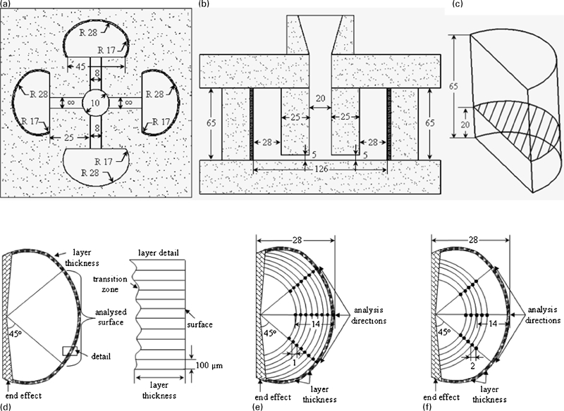
Experimental set including semi-cylindrical samples arrangement in the a FRS–PTSA mould, b sample size, c cut sample for structural analysis and d the analysis procedure to evaluate the surface layer thickness, structure parameters in the sample e section and f centre
Different coatings (Table 1) were applied on the concave surface of these sample moulds (see Fig. 1a). All of the coatings were prepared in identical conditions, including fine sized materials up to 0·01 mm grain size, with the same binder type, and applied on the mould surface using the same procedures (0·35–0·40 mm coating thickness).19 As binder, an expanded polystyrene - toluene solution (30 wt. polystyrene) was used, at 0.612 g cm−3 density and 1100 cP at 20°C, viscosity. The representative physical characteristics of the binder components are as follows: the expanded polystyrene (EPS) [0.0167 g cm−3 density; Tt = 240°C melting point] and toluene [0.8669 g ml−1 density; −95°C melting point; 110.6°C boiling point; 0.590 cP at 20°C, viscosity], respectively.
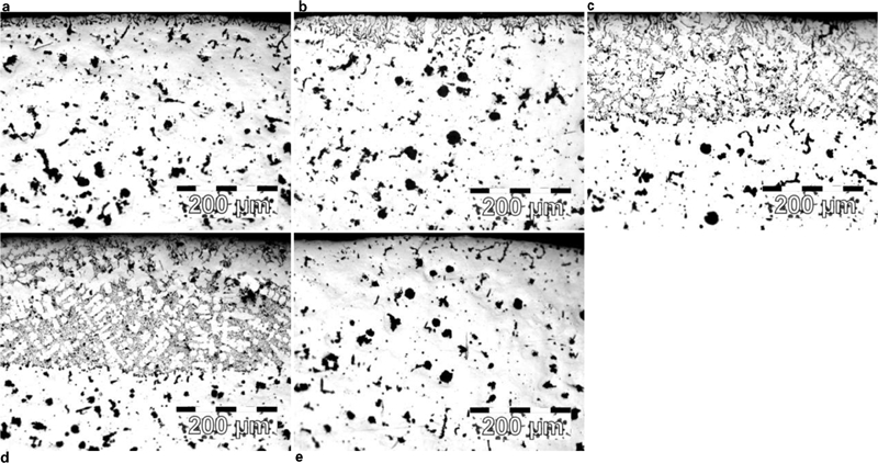
Coating materials
*FRS–PTSA: furan resin sand–P-toluol sulphonic acid. NRS: Novolak resin coated sand – Quik-Cup.
**Talc (wt.): 33CaO, 14MgO, 28SiO2, 2Fe2O3; 1.0 humidity; 25 loss on ignition at 1000°C.
***FeSiCaMgRE alloy used for Mg-treatment to obtain ductile iron.
Standard Quik-cup™ cups (0.35 kg, CM = 7.3 mm) were used as the alternative moulding system, to represent moulds without any sulphur source: phenol-formaldehyde resin (Novolak) coated sand (NRS) (Croning process). The typical thermophysical properties of these ceramic cups include: 1487 W s1/2 m−2 K−1 thermal diffusivity, 1280 J kg−1 K−1 specific heat, 1·08 Wm−1 K−1 thermal conductivity and 1600 kg m−3 density.17,18 Some coatings (Table 1) were also applied on the inner surface of these bonded silica sand cups.
S bearing coatings with added FeS2 powder (49–52 wt-S) or elemental sulphur (Sorg) were used as a supplementary source of sulphur at the metal/mould interface for the FRS–PTSA mould. In the case of the moulds without sulphur, such as the NRS mould, the coatings with added sulphur were used to check if sulphur migration into the iron melt is the mechanism by which graphite degenerates in the surface layer of Mg treated irons.
Two coatings, based on MgO or a mixture (CaO+MgO+Talc), were expected to act as a desulphurising layer, and were found to limit surface graphite degeneration in heavy section ductile iron production in a furan resin–PTSA moulding system.12
Two other coatings were created to provide a high nodularising potential at the casting surface, by incorporating Mg and RE as metallic/alloy nodularising elements. One coating used fine sized FeSiCaMgRE alloy based on the noduliser in these experiments, and another included Mg powder, obtained by Mg filings, with FeSi75 powder.19
The semi-cylindrical samples from the FRS–PTSA moulds (Fig. 1c) and cup samples from the NRS moulds were sectioned and prepared for metallographic analysis in standard conditions. The thickness of the surface layer of the semi-cylindrical samples was evaluated along the total 30 mm length (‘analysed surface’ - Fig. 1d) (25 mm for cup samples, in similar conditions), with 100 μm between points for analysis, avoiding the end (corner) effects for both types of samples. The thickness of the surface layer was expressed as an average and a maximum from a total of 300 and 250 measurements, respectively.
The structure in the surface layer was analysed along 10 parallel lines from the diameter to the surface. A total area of 800 μm2 was analysed, in the surface (affected) layer, the transition zone between affected layer un-affected layer and in immediate ‘good’ area immediate un-affected zone. The structure variation on the semi-cylindrical samples section was evaluated along three radial directions (Fig. 1e), up to the centre of each sample, with 1·0 mm separating the analysed points. The structure was also analysed at five positions 2 mm apart in the centres of the semi-cylindrical (Fig. 1f) and the cup samples; the average parameters for the structures were recorded.
Results and discussion
In order to investigate the possible effects of two moulds systems with and without sulphur and mould coatings with either added sulphur or a desulphurisation capability, Mg treated irons (0·03Mgres) were intentionally processed at low Mg levels for ductile iron.
It should be noted that the two types of moulds and their respective binder systems were selected to contrast different sulphur levels in the moulding media. The selection of thermal analysis cups to represent moulds with low sulphur content introduced a different pouring rate while filling the mould, and also solidification with an open top surface. The filling rate determined by cooling curves parameters were 0·04 kg s−1 for semi-cylindrical samples and 0.028 kg s−1 for Quik-cup samples, respectively. For that reason the Mg loss at the exposed surface would be expected to be higher that in the enclosed moulds representing the high sulphur moulding media, FRS–PTSA. The two types of moulds allow the role of sulphur in the mould to be studied and the impact, if any, by using open thermal analysis cups would be to drive the NRS results closer to the FRS–PTSA results.
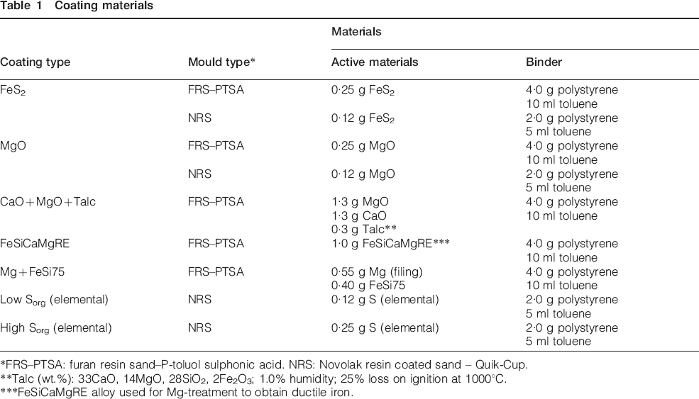
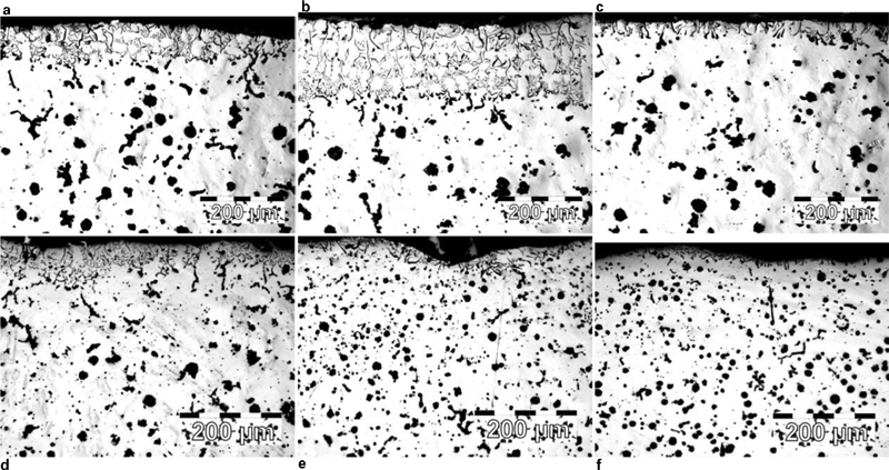
The ductile iron microstructures in the casting surface region are presented in Fig. 2 for FRS–PTSA moulds and in Fig. 3 for NRS moulds. The extent of an abnormal surface layer is influenced by both the moulding system and type of applied coating (Table 2, Fig. 4).
Iron structure in surface layer of ductile iron semi-cylindrical samples solidified in FRS–PTSA mould
Iron structure in surface layer of ductile iron cup samples solidified in NRS mould
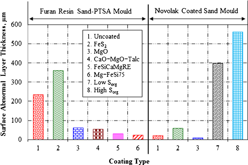
Influence of mould and coating type on average surface layer thickness of ductile iron castings [Sorg – elemental sulphur]
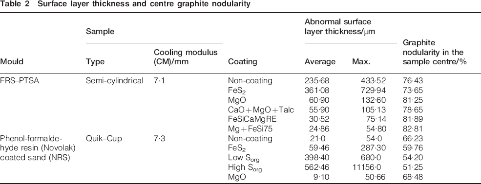
Surface layer thickness and centre graphite nodularity
In uncoated mould samples, there is a big difference between solidification in FRS–PTSA moulds and NRS moulds affecting the abnormal graphite types at the surface layer, including degenerate graphite, vermicular/compacted and/or lamellar morphologies. In NRS moulds, the occurrence of degenerate graphite in the surface layer is less likely: samples showed no influence or a limited layer less than 25 μm average thickness, up to 55 μm maximum.
FRS–PTSA moulds evidently prompted degenerate graphite in the surface layer of the ductile iron test castings. The thickness of this layer increased 10 times compared to NRS moulds with an average thickness up to 235 μm and up to 435 μm maximum thickness.
The application of different mould coatings had a strong influence on the graphite morphology in the casting surface layer, prompting deterioration to lamellar graphite, or in contrast minimising the thickness of the surface layer by protecting graphite nodularity.
The intentional use of sulphur in some coatings significantly increased the layer thickness, in both moulding systems. Comparing the effects of an intentional FeS2 content in the coated test moulds, the average layer thickness increased three times in NRS moulds and by more than 50 in FRS–PTSA moulds. The behaviour of this coating was through newly introduced sulphur in the NRS moulds and by supplementary sulphur, in the second case.
The state of any sulphur at the metal/mould interface appears to have a strong influence on the level of graphite degeneration, by affecting the sulphur capacity to diffuse into the Mg treated iron. Elemental sulphur (Sorg) bearing coatings applied to the NRS moulds led to more than 20 times increase in the ductile iron degenerate surface layer with higher elemental sulphur in this coating further increasing the thickness. This sulphur source led to a 2·4 times increase of the surface layer thickness in NRS moulds (no mould sulphur) compared to uncoated FRS–PTSA moulds, which have sulphur in the binder system. This suggests that even though sulphur migration occurs in both these examples the elemental sulphur contained in a coating diffuses more rapidly than the combined sulphur present in the binder.
The coatings based on desulphuriser type materials, such as MgO, a mixture (CaO+MgO+Talc) or a Mg bearing ferrosilicon, provided some protection at the metal/mould interface against graphite degeneration, as the average thickness of the layer decreased 3·8 times (MgO), 4·2 times (CaO+MgO+Talc) and up to 7–10 times for Mg bearing FeSi, in sulphur containing FRS–PTSA moulds. In this respect, a mechanical mixture of Mg+FeSi75 appears to be more effective than a FeSiCaMgRe alloy.
Both coatings with magnesium led to better results, compared to the (CaO+MgO+Talc) coating. The magnesium was either integral in a [FeSiCaMgRE alloy] or a separate constituent in a mechanical mixture [Mg+FeSi75]. In the lower residual magnesium (0·03) irons the thickness of the surface layer decreased significantly and was eliminated in irons with the higher magnesium (0·036), employing the same samples in the same type of mould, from results published in another paper.20
These experiments not only confirmed the role of sulphur, delivered by the moulding and/or coremaking system(s), but also its ability to diffuse into molten iron to react with the residual magnesium. A similar behaviour was exploited by adding sulphur (FeS2) after Mg treatment in a treatment ladle, to obtain a compacted graphite iron. A limited sulphur addition (0·002–0·02 wt-S) transformed nodular+vermicular graphite irons or nodular graphite irons (0·025–0·04 wt-Mg) to compacted/vermicular graphite cast irons, with a controlled intermediate structure (>80 compacted graphite) in high volume commercial foundry conditions.21–26
In this respect graphite characteristics are influenced by a sulphur addition not only in the surface layer but also throughout the section up to the centre of the test samples. The graphite characteristics were evaluated with automatic image analysis (analySIS FIVE Digital Imaging Solutions software), which evaluated the following parameters
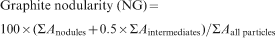

Table 2 and Fig. 5 illustrate the graphite nodularity in the centre of the two types of sample: the semi-cylindrical sample (28 mm wall thickness, 0·56 kg, CM = 7·1 mm) in an FRS–PTSA mould and a cup sample (35 mm wall thickness, 0·35 kg, CM = 7·3 mm) in an NRS mould, both uncoated and with different coatings. In the iron series with lower residual magnesium (0·03) the graphite nodularity was at the lowest acceptable limit (76 in the FRS–PTSA mould), and 10 lower in the cup-type sample, due to higher Mg loss at the open surface.
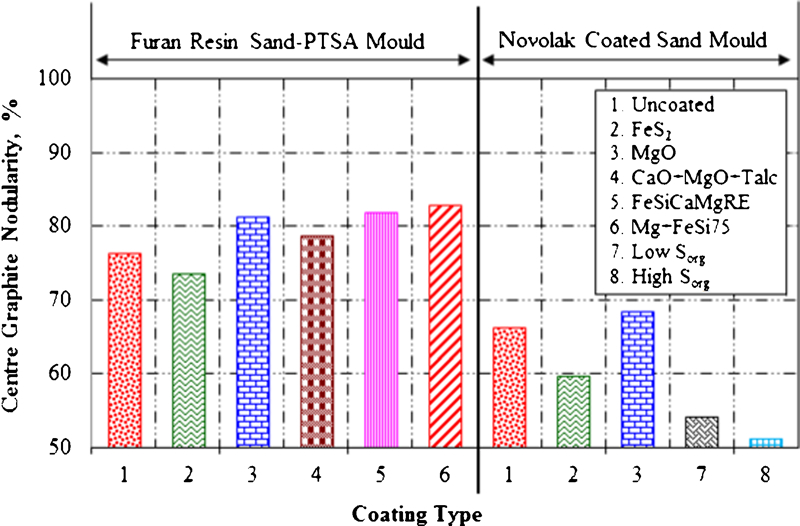
Influence of mould and coating type on graphite nodularity in centre of ductile iron castings [Sorg – elemental sulphur]
Sulphur bearing coatings also affected graphite nodularity in the centre of the experimental castings, for both moulding systems, more so for NRS mould samples and especially for elemental sulphur bearing coatings. In contrast, all desulphurisation type coatings, including Mg bearing coatings, led to higher graphite nodularity in the sample centres, for both mould types, especially if the Mg is metallic and mixed with FeSi75.
Figures 4 and 5 show the complementary results in the ductile iron test castings, with variations in thickness of the degenerated graphite surface layer and loss of graphite nodularity in the casting centre. As the surface layer thickness increased, the graphite nodularity decreased in the casting centre. The two characteristics are in close relationship, as shown in Fig. 6. The data show that elemental sulphur in a coated NRS mould substantially increases the surface layer effect. The data also show that the assumed greater loss of Mg from the open surface in the NRS test coupled with a slower fill rate consistently gave lower nodularity than that found with the FRS–PTSA test.
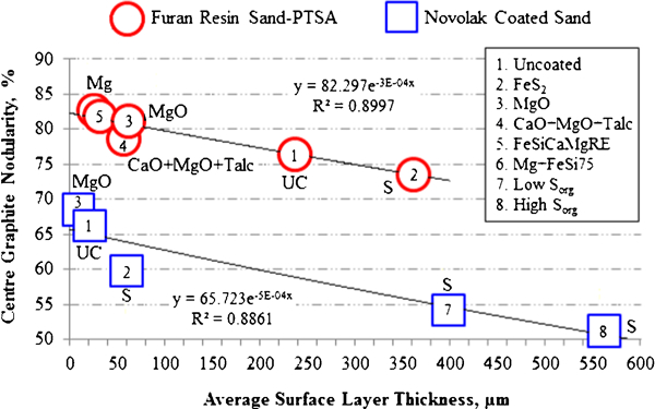
Graphite nodularity in casting centre and relationship with surface layer thickness [Sorg – elemental sulphur]
Generally, sulphur present at the metal/mould interface, independently of its source, made the graphite degeneration more severe at the casting surface, and also reduced graphite nodularity over the entire section.
The graphs in Fig. 7 show the variation of characteristics of the graphite compactness (nodularity, shape factor and aspect ratio) across the section of the semi-cylindrical samples, solidified in FRS–PTSA moulds. Higher nodularity and shape factor and lower aspect ratio levels of graphite phase represent a better ductile iron structure.
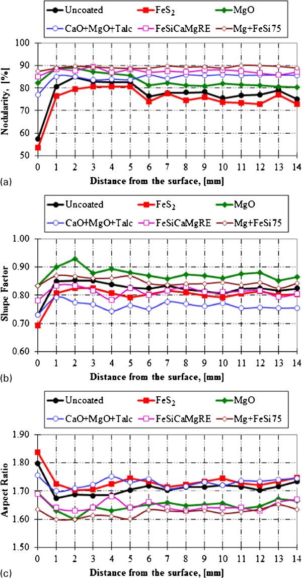
Influence of FRS–PTSA mould coating on variations in semi-cylindrical sample section of a graphite nodularity, b shape factor and c aspect ratio
The parameters describing graphite compactness, for nodular graphite over the main area, are related to the thickness of the degenerate graphite layer. Considering the distance from the surface, where the maximum level of each parameter was obtained, it typically occurred between 1 and 3 mm, depending on the coating. In general the values were 2·0 mm for non-coating, 3·0 mm for an S bearing coating and 1–2 mm for desulphurisation type coatings, especially if Mg was in the coating.
It is presumed that the MgO or (MgO+CaO+Talc) coatings served to remove sulphur in the boundary layer between the coating and the mould face, and the Mg–FeSi coatings performed an additional role to provide supplementary magnesium to regenerate the nodularising potential prior to solidification. This special effect is important not only on the surface layer of heavy castings, but also on the body of smaller, thinner castings.
It has been shown that the degenerate graphite surface layer is mainly attributable to a metal–mould chemical interaction, especially where sulphur is available. It is important to combine a desulphurisation capability with a source of magnesium for an effective protective coating. This dual role supports the application of coatings containing active magnesium, derived from Mg–FeSi materials.
Summary
The relative performance of coatings for FRS moulds [P-toluol sulfonic acid (PTSA) as hardener] (FRS–PTSA), compared to NRS moulds was evaluated by analysing the degenerate graphite surface layer of ductile iron test castings in conjunction with the nodular graphite characteristics over the entire section.
It was found that the both moulding systems, with and without sulphur, and the mould coatings, with either added sulphur or a desulphurisation capability are important factors for graphite degeneration.
In NRS moulds, the surface layer of degenerate graphite is less likely to be present or have a limited thickness, while the FRS– PTSA moulds aggravated graphite degeneration in the surface layer, with the thickness increasing up to ten times compared to the NRS moulds.
Of the two moulds types, thermal analysis cups with lower sulphur were filled more slowly, had similar cooling modulus, but an open top surface leads to greater Mg loss than that in the enclosed moulds representing the high sulphur FRS–PTSA moulds. Using open cups would drive the NRS results closer to the FRS–PTSA results.
It was reconfirmed that the FRS–PTSA moulding system releases sulphur as a primary cause of graphite degeneration in the surface layer of ductile iron castings.
The application of a mould coating strongly influenced graphite deterioration in the surface layer of castings, either driving graphite degeneration towards vermicular and lamellar morphologies, when using S type coatings, or conversely, limiting the thickness of the surface layer by using desulphurisation type coatings.
Independently of the sulphur source at the metal/mould interface, the presence of this element had an adverse effect on graphite quality at the surface of ductile iron.
If the coatings employed desulphurisation materials, such as MgO, a mixture (CaO+MgO+Talc) or Mg bearing FeSi, they protected the graphite at the metal/mould interface, decreasing the average layer thickness (3·8∶4·2∶7–10 times, respectively) in FRS–PTSA moulds. In this study a mechanical mixture of Mg with FeSi75 appears to be more effective than a FeSiCaMgRE alloy.
It is presumed that the MgO or (MgO + CaO + Talc) based coatings acted to remove any S - released by the moulding system.
The Mg-FeSi coatings had an additional role to desulphurisation providing supplementary Mg to raise the nodularising potential prior to solidification. This dual activity is available with coatings containing active magnesium, derived from (Mg)FeSi materials.
Footnotes
Acknowledgements
The work has been funded by the Sectoral Operational Programme Human Resources Development 2007–2013 of the Romanian Ministry of Labour, Family and Social Protection through the Financial Agreement POSDRU/6/1·5/S/19. The authors would like to recognise and thank Michael Barstow for reviewing and editing this paper.