
Abstract
Nanostructured martensite–austenite microstructure was achieved by a quenching–partitioning–tempering (Q–P–T) treatment of high carbon low temperature bainitic steel. Microstructure observations showed that the nanostructured steel consisted of fine martensite (about 25 nm in thickness), retained austenite and carbides. X-ray diffraction analysis indicated that carbon was partitioned into austenite after martensite transformation. High hardness (about 655 HV1) and relatively high retained austenite fraction (0·36–0·41) was attained. The heat treatment times were greatly reduced, nearly equal or higher hardness and retained austensite fraction were achieved by Q–P–T treatment, compared with low temperature super bainite process.
Introduction
Low temperature bainite, or super bainite, through transformation at temperatures as low as 200–300°C,1,2 which consist of bainitic ferrite plates (20–65 nm in thickness) and carbon enriched retained austenite without carbide precipitation, has been developed.3–5 Ultimate tensile strengths of 2300 MPa in tension have been routinely obtained, ductility in the range 5–30 and toughness in excess of 30–40 MPa m1/2.2,6 However, it takes several days to transform even if Co and Al are added to accelerate the bainite transformation.7
Regarding quenching and partitioning (Q&P) process, the formation of cementite are suppressed by appropriate alloying (such as Si and Al), the carbon partitions from the supersaturated martensite to the untransformed austenite phase.8,9 While Q&P treatment can preserve certain amount of retained austenite, the ductility and toughness of high strength steel can be chanced.10 In order to further raise the strength of steels by precipitation strengthening and maintain adequate ductility, a quenching–partitioning–tempering (Q–P–T) process is proposed to modify the Q&P technology.11,12 For this process, the steel contains certain amount of carbide forming elements (such as Nb and Mo), and the mechanical properties of steel can be improved by Q–P–T process depending on precipitation strengthening.13–15 The average thickness of martensite laths are several tens of nanometre and fine carbides are dispersedly distributed in martensite matrix.12 The Q–P–T treated steel exhibits tensile strength as high as over 2000 MPa and total elongation over 10.12 However, the volume fraction of retained austenite is usually less than 15 in low or/and medium carbon Q–P–T steels.12
Retained austenite in dual phase steel is believed to improve the ductility and increase the strain hardness rate, due to its transformation to martensite during straining.16 The increase in final retained austenite fraction is strongly related with the initial carbon content of the steel.17 Therefore, the present work combines the concept of low temperature bainite and the novel processing technique of Q–P–T to design low cost nanostructured high carbon steels, which not only have ultrahigh hardness, but also contain sufficient quantity of the retained austenite.
Experimental
The alloy was homogenised at 1150°C for 1 day, while sealed in the vacuum annealing furnace, followed by furnace cooling to ambient temperature. The chemical composition of the alloy is listed in Table 1. Regarding low temperature super bainite transformation, specimens were austenitised at 850°C for 1800 s and then isothermally transformed at temperatures in the range 200–300°C for different time intervals before quenching into water. Regarding to Q–P–T treatment, specimens were austenitised at 850°C for 1800 s and then quenched into water at 0 and 50°C respectively. This was followed by partitioning tempering at 450°C in molten salt bath for different time periods, and finally water quenched to room temperature. The Ms and Mf of the present steel are calculated as 80 and −74 °C by respectively J-MatPro.18
Chemical composition of super bainitic steel (wt-)
Transmission electron microscopy (TEM, JOE 2010 HT) specimens were machined into 3 mm diameter rods which were sliced into 100 μm discs. These were ground down to 50 μm in thickness using 2000 grit silicon carbide paper, for electropolishing at 50 V using a twin jet unit. The electrolyte consisted of 5 perchloric acid, 15 glycerol and 80 methanol. TEM analysis was conducted on the specimens to determine true plate thickness t of the bainitic ferrite and martensite, by measuring the mean linear intercept L = πt/2,7 in a direction normal to the plate length. The type of carbide was determined by utilization of a selected area electron diffraction pattern (SADP).
X-ray diffraction (XRD, Xpert Pro MPD) was utilised to determine the volume fractions of retained austenite, bainite and martensite calculated by means of integrated intensities of the (111), (200), (220) and (311) austenite peaks, the (110), (002), (112) and (022) bainite peaks, and (110), (200), (211) and (202) martensite peaks.19,20 The measurement error of retained austenite volume fraction was 0·015. The carbon concentration in austenite was estimated by using the measured lattice parameters.21 The scanning step size of XRD peak was 0·03342°, and the calculation error of carbon concentration in austenite was about 0·10 wt-. The samples were step scanned in an X-ray diffractometer, operating at 40 kV voltage and 45 mA current, using Cu Kα radiation. The 2θ scan angles ranged from 20 to 100°.
Vickers hardness tests are reported as the average of at least 10 tests. The tests were conducted using a 1 kg load, and each value represents the mean of those measurements.
Results
Transformed microstructures
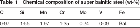
Nanostructured bainite structures which consist of bainitic ferrite plates and carbon enriched retained austenite without carbides precipitation, was produced by low temperature bainite transformation. Figure 1 shows the TEM images of the bainitic microstructure obtained by isothermal transformation at 200°C for 9 days and 300°C for 1 day respectively. The thickness of the bainitic ferrite plates were about 50 and 100 nm for the specimens treated at 200 and 300°C respectively.
Nanostructured bainitic microstructures obtained by low temperature transformation at a 200°C for 9 days and b 300°C for 1 day
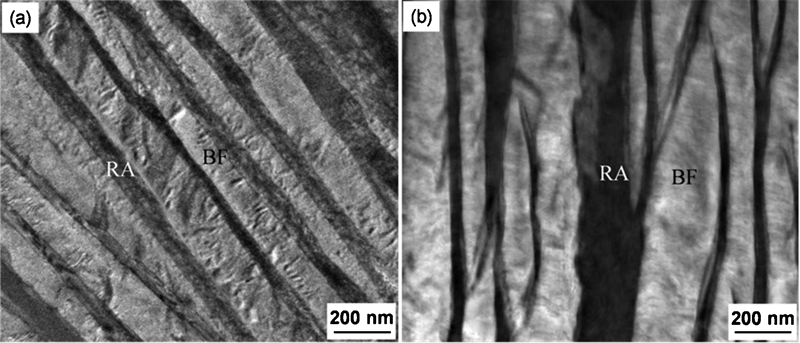
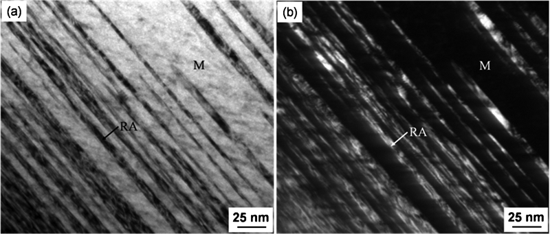
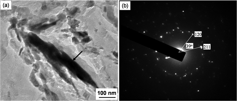
Nanostructured martensite structures, which consist of martensite plates and carbon enriched retained austenite with carbide precipitation, were produced by Q–P–T treatment. The average thickness of martensite plates is about 25 nm (Fig. 2). With increasing partitioning–tempering time (1800 s), martensite plates and retained austenite were coarsened, the average size of the carbides were dispersedly distributed in martensite and retained austenite were several nanometres (Fig. 3a). Further coarsening of martensite occurred when partitioning–tempering time increased up to 7200 s (Fig. 3b), and carbides were further coarsened and spheroidised. The carbides in the specimen tempered at 450°C for 7200 s were identified to be M3C by the SADP (Fig. 4). M2C, M7C3 and M23C6 type carbides were identified by similar method.
Nanostructured martensitic microstructures obtained by Q–P–T treatment: specimen was quenched at 0°C and then partitioned–tempered at 450°C for 60 s
TEM images of the carbides precipitated in martensite and retained austenite in specimen quenched at 0°C and then partitioned–tempered at 450°C for a 1800 s and b 7200 s
TEM images of carbide M3C in Q–P–T specimen tempered at 450°C for 7200 s
Volume fraction of austenite and hardness
Figure 5 shows the XRD analysis and measured hardnesses of the microstructures transformed at low temperature and treated by Q–P–T. In low temperature transformed bainite microstructure, the volume fraction of retained austenite increases from about 0·27 in the specimen isothermally held at 200°C to 0·40 in the specimen isothermally held at 300°C. Accordingly, the hardness decreases sharply from about 610 to 400 HV1 with increasing transformation temperature. The ultrahigh hardness of low temperature bainitic steel is mainly attributed to nanostructured bainite and retained austenite.1,6 The volume fractions of retained austenite in the specimen directly quenched are 0·35 (quenched at 0°C) and 0·37 (quenched at 50°C) respectively. For these two quenched specimens, the maximum retained austenite fractions of 0·38 and 0·41 were obtained when partitioned and tempered at 450°C for 300 s. It is seen that more retained austenite is obtained compared with that obtained by direct quenching, indicative of some carbon partitioning from the martensite during partitioning.10 When specimens were partitioned and tempered for longer times (1800 s), the amount of austenite was decreased due to the decomposition of some retained austenite10 (the volume fraction of carbides was ignored in the XRD calculation).
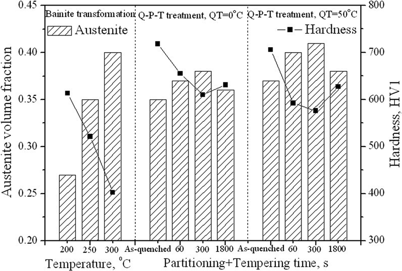
Volume fraction of retained austenite and measured hardness of microstructures transformed at low temperature and treated by Q–P–T process
The maximum hardnesses, 718 and 706 HV1, were obtained in the specimens as quenched at 0 and 50°C respectively. The hardness of the specimens was decreased and remained to be about 655 and 592 HV1 for these two specimens when partitioned and tempered at 450°C for 60 s. When the partitioning–tempering increased up to 300 s, the hardness was decreased. At this stage, some carbon was partitioned into retained austenite. The hardness reached about 631 and 627HV1 respectively, when the holding time was further increased up to 1800 s, indicating carbide precipitation strengthening. As the quenching temperature increased, the volume of retained austenite was increased, but the hardness was decreased. The ultrahigh hardness of Q–P–T steel is mainly attributed to nanostructured martensite, retained austenite and fine carbides.14,15
Austenite carbon content
As the bainite was transformed at higher transformation temperature, the carbon content of retained austenite increased. There was a significant amount of solid solution carbon in austenite (1·56–1·79 wt-), higher than that predicted by  phase boundary (Fig. 6a). For the Q–P–T process; the maximum level of carbon enrichment in austenite (1·87 and 2·11 wt- in the specimens quenched at 0 and 50°C respectively) was obtained when specimens were partitioned and tempered at 450°C for 300 s (Fig. 6b). When specimens were partitioned and tempered at 450°C for 1800 s, less austenite enrichment was observed, possibly due to carbide formation for long partitioning period.10
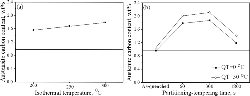
Retained austenite carbon contents during a bainite transformation and b Q–P–T treatment: horizontal line represents average carbon content
Discussion
Carbon partitioning from bainite or martensite to austenite
During bainite transformation, the excess carbon in the bainite partitions into the retained austenite (Fig. 7a),22 forcing the next plate to grow from carbon enriched austenite.3 As expected from the incomplete reaction phenomenon,3 the carbon content in carbon enriched retained austenite (6·91–7·93 at-) was higher than  phase boundary predicted.
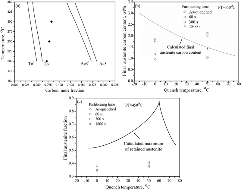
a carbon concentration in retained austenite of low temperature transformed bainitic microstructure, b carbon concentration in retained austenite of Q–P–T treated microstructure and c comparison of experimental austenite volume fraction with calculated retained austenite volume fraction for Q–P–T treated specimens
During Q–P–T treatment, the excess carbon in the martensite partitions into the retained austenite.8 The variations in retained austenite carbon content and volume fraction after Q–P–T treatment of steel were compared with the maximum austenite achievable according to the constrained carbon equilibrium model described (Fig. 7b and c).14,15 During the early stage, the carbon concentration and volume fraction of retained austenite were increased with increasing partitioning–tempering time (⩽300 s). Austenite fraction of experimental values below the calculated curve likely reflects incomplete partitioning, such as carbide formation or carbon segregation to dislocations in martensite.23,24
Transformation kinetics
The calculated martensite start temperature (Ms), martensite finish temperature (Mf)18 and TTT diagram with MUCG 83.Mod program22 are shown in Fig. 8a. The upper C curve represents the onset of reconstructive transformations such as allotriomorphic ferrite and pearlite, whereas the lower curve is for bainite, and horizontal line represents martensite transformation.25 It is clear that bainite can be obtained by transforming at very low temperatures. The amount of martensite formed at the quenching temperature QT can be predicted by the Koistinen–Marburger relationship26

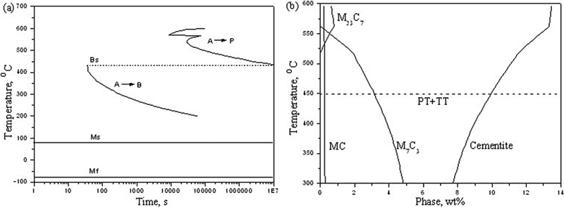
a calculated TTT diagram for the initiation of reaction and b calculated equilibrium phase fractions (wt-) of carbides as function of partitioning–tempering temperature of Q–P–T processed steel
The calculated precipitation of carbides using J-MatPro18 is shown in Fig. 8b. It is seen that carbides can precipitate during a wide tempering range. The tempering temperature of 450°C was chosen to obtain a large amount of fine carbides distributing dispersedly in steel matrix.14 In the meantime, the selected temperature can also satisfy the requirement of fast carbon partitioning from the supersaturated martensite phase to the untransformed austenite phase, thereby increasing the stability of the residual austenite upon subsequent cooling to room temperature.13
Conclusions
High carbon steels were treated by low temperature bainite transformation and Q–P–T process respectively. Microstructural features, retained austenite fraction and hardness were compared. Nanostructured dual phase microstructures were obtained in these two conditions. The heat treatment time was greatly reduced, and nearly equal or higher hardness and retained austensite fraction were achieved by Q–P–T process, compared with low temperature bainite transforming process.
Footnotes
Acknowledgements
The authors express their thanks to the financial support from the International Science and Technology Cooperation Program of China under grant no. S2012ZR0211.