
Abstract
Experimental and numerical studies of slurry generation using a cooling slope are presented in the paper. The slope having stainless steel body has been designed and constructed to produce semisolid A356 Al alloy slurry. The pouring temperature of molten metal, slope angle of the cooling slope and slope wall temperature were varied during the experiment. A multiphase numerical model, considering liquid metal and air, has been developed to simulate the liquid metal flow along the cooling channel using an Eulerian two-phase flow approach. Solid fraction evolution of the solidifying melt is tracked at different locations of the cooling channel following Schiel's equation. The continuity, momentum and energy equations are solved considering thin wall boundary condition approach. During solidification of the melt, based on the liquid fraction and latent heat of the alloy, temperature of the alloy is modified continuously by introducing a modified temperature recovery method. Numerical simulations has been carried out for semisolid slurry formation by varying the process parameters such as angle of the cooling slope, cooling slope wall temperature and melt superheat temperature, to understand the effect of process variables on cooling slope semisolid slurry generation process such as temperature distribution, velocity distribution and solid fraction of the solidifying melt. Experimental validation performed for some chosen cases reveals good agreement with the numerical simulations.
List of symbols
specific heat/J kg−1 K−1
drag coefficient
particle size of air/m
volume fraction
maximum solid fraction
liquid phase volume fraction
volume fraction of air
solid phase volume fraction
gravity acceleration/m s−2
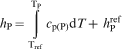
enthalpy/J kg−1
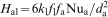
heat transfer coefficient/W m−2 K−1
thermal conductivity/W m−1 K−1
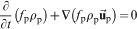
momentum exchange coefficient/kg m−3 s−1
latent heat/J kg−1
Nusselt number
Prandlt number
energy exchange by heat transfer/J m−3 s−1
Reynolds number
time/s
solver temperature/K
temperature at point G/K
temperature at point K/K
liquidus temperature of alloy/K
melting temperature of pure aluminium/K
reference temperature/K
solidus temperature of alloy/K
velocity vector/m s−1
momentum exchange due to drag/kg m−2 s−2
viscosity/kg m−1 s−1
stress–strain tensors/kg m−1 s−2
time step/s
Introduction
Semisolid processing (SSP) of metals (alloys) came into existence in the 1970s and is considered now as a potential manufacturing technology for components in automobile, aviation, electronic and machine tool industries. Semisolid metal processing enables manufacturing of near net shaped components with good mechanical and tribological properties and with high dimensional tolerance accuracy.1,2
Semisolid processing has significant advantages over conventional die casting, such as minimising the macrosegregation and solidification shrinkage and reducing the forming temperature.3 The key feature that allows the formability of semisolid alloys into complex shapes is the thixotropic flow behaviour at semisolid temperature,4 which is caused by the non-dendritic morphology of the primary phase in the microstructure. Such flow properties and formability are not possible with conventional die casting techniques.5
Several processes are available for preparation of semisolid slurry. These include stir casting, electromagnetic stirring, mechanical or ultrasonic vibration, low pouring temperature and partial remelting, stress induced and melt activated process, thermomechanical processing, magnetohydrodynamic stirring and cooling slope.6–8 However, most of the above methods have proven to be too complex as well as expensive for successful commercial exploitation of SSP technology. In this respect, cooling slope method offers some promise, as it is one of the simplest and most cost effective processes to prepare the semisolid slurry for thixocasting and rheocasting. When the superheated molten alloy flows over the cooling slope, the temperature drops below the liquidus temperature and α-Al crystals starts to nucleate. The initial contact with the cold surface of the slope promotes the necessary undercooling for solid nucleation; therefore, solid crystals appears in the region.9 α-Al crystals form globular equiaxed grains and the melt becomes semisolid slurry up to the end of slope.
Haga and Suzuki10 have performed castings of Al–6Si alloy using a cooling plate and studied the effect of cooling rate on the microstructure of solidified ingots. Haga11 also has used cooling slope for semisolid strip casting. Birol12–14 has published a number of papers on cooling slope processing of A390, A357 and A365 alloys. Gencalp and Saklakoglu1 have performed experimental investigation of cooling slope processing of A380 Al alloy under vibration. Taghavi and Ghassemi2 and Legoretta et al.15 have performed a series of experiments to investigate the effect of cooling length and tilt angle of the slope on thixotropic microstructure evolution in case of A356 Al alloy. Guan et al.16 numerically studied the effect of slope angle and pouring temperature on the exiting alloy temperature.
The present study is focused to bridge the gap between experimental investigations11–14,17,18 and some recent numerical simulations.16,19 The numerical simulations performed by earlier researchers lack experimental validation. The experimental findings available in the literature show deviating results from each other. In this context, a need has been felt to perform a comprehensive experimentally validated numerical study of cooling slope slurry production of aluminium alloys. This is the focus of the present study, which is done using A356 aluminium alloy. The main objective of the numerical model is to relate the process variables such as pouring temperature, slope angle and wall temperature of the slope to the slurry temperature distribution, velocity field and solid fraction distribution.
Experimental
A356 Al alloy (with a composition of 6·8Si–0·34Mg–0·18Mn–0·14Cu–0·11Fe–0·04Ti–92·39Al) has been used in the present study. A cooling slope with stainless steel body is employed to produce semisolid slurry in the present work. A schematic diagram and photograph of the experimental facility is shown in Figs. 1 and 2 respectively. A356 ingot is melted in a resistance heating furnace having 5 kg capacity set at 1023 K. For performing the experiments, 2 kg of A356 alloy is melted in a silicon carbide crucible located within the resistance furnace. The degassed melt is then allowed to cool up to the desired pouring temperature and poured along the slope. The cooling plate is adjusted at two different slope angles of 60 and 45° with respect to the horizontal plane and preheated at two different temperatures (60 and 150°C) by oil circulation underneath. The surface of the plate is coated with a thin layer of boron nitride in order to avoid sticking of the molten alloy and to facilitate a smooth melt flow. A 10 mm hole with a stopper arrangement at the bottom of the silicon carbide crucible enables bottom pouring at a controlled rate. The slurry from the cooling slope fills a mild steel mold, preheated to 100°C and then allowed to cool in air.
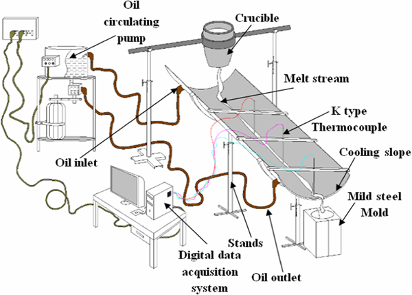
Schematic diagram of experimental facility
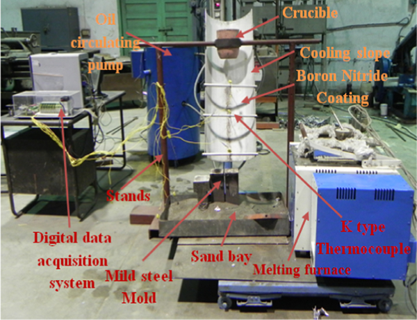
Photograph of experimental set-up
All the experiments, performed for different pouring temperatures and different slope angles, are repeated twice to ensure the reproducibility of results. Temperature is monitored along melt stream at three different locations of the cooling channel using K type thermocouples, and their output has been recorded using a rapid data acquisition software (Scada).
For comparing cooling slope results with conventional castings, some samples were made by directly pouring the melt having low superheat (∼10°C above liquidus) into the preheated metallic moulds. After experiments, test samples were cut from the middle section of the cast billets and prepared for metallographic investigation. The samples were then etched by Keller solution and examined using an optical microscope.
Numerical model
In the present work, commercial CFD software Fluent (version 12·1) has been used to develop a three-dimensional (3D) non-isothermal numerical model of cooling slope semisolid slurry generation process using Eulerian two-phase flow approach. The hexahedral grid system used for the simulations is shown in Fig. 3.
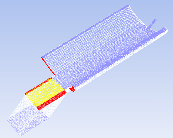
Model (3D) of cooling channel and holding bath
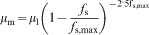
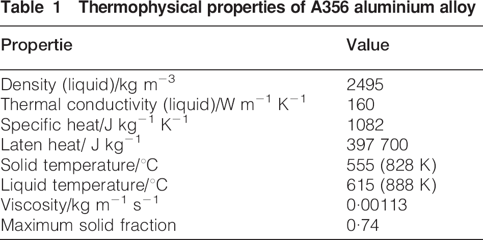
Eight sets of simulations have been carried out at different processing conditions using the abovementioned model to investigate the effect of various process parameters such as pouring temperature and slope angle of the channel on the thermodynamic state of the semisolid slurry. Velocity inlet boundary condition has been specified at the top of the cooling slope, where the superheated liquid alloy is poured into the slope. Thin wall boundary condition has been used to model the cooling slope with symmetry along the middle section. The molten alloy flows by gravity along the slope, exposed to air at the top. Thermophysical properties of commercial A356 aluminium alloy, used in the present work, are shown in Table 1. Liquid aluminium melt and, subsequently, the formed semisolid slurry are considered as a single phase instead of two phases, where solid fraction evolution of the solidifying melt is tracked explicitly using Schiel's equation. Air is considered as the secondary phase in the present model. The non-Newtonian behaviour of the formed semisolid slurry is represented by the mixture viscosity model according to the model presented by Ishii and Zuber20
Thermophysical properties of A356 aluminium alloy
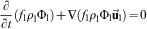
Continuity
The volume fractions of the phases satisfy the following relationship


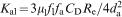
Energy

Solidification model
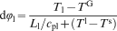
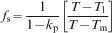
The present A356 Al alloy has distinct liquidus (615°C)23,24 and solidus temperature (555°C).23 Based on the liquid fraction and latent heat of the alloy, the temperature of the alloy is modified continuously by introducing a modified temperature recovery method (as shown in Fig. 3) in the range of temperature, in which alloy becomes solidified, i.e. at temperature range in which crystallisation of the alloy starts (liquidus temperature), and total crystallisation is completed (solidus temperature), i.e. where alloy becomes complete solid. Though the solidification curve of semicrystalline alloy is essentially non-linear, assuming linearity of the curve does not make significant deviation in liquid fraction. Mass transfer and diffusion between the phases have been neglected in the present model. Hence, the liquid fraction of the alloy is tracked by solving a scalar transport equation (10) with zero diffusion flux
Results and discussion
Simulation results
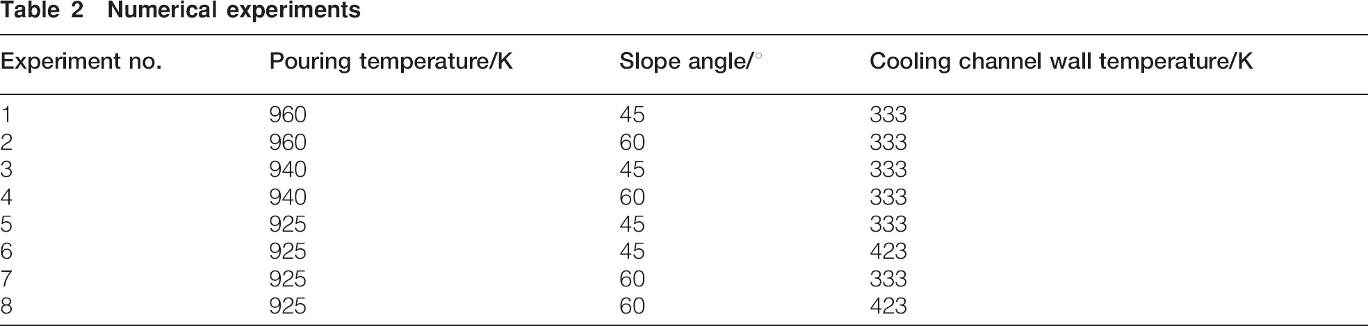
Cooling slope length, tilt angle of the slope, cooling rate and pouring rate of the melt, cooling channel wall temperature and initial superheat of the melt are the process variables which affect the state of the semisolid slurry generated. In the present work, eight case studies have been performed (conditions shown in Table 2) to show the effect of the three key process variables, namely, the slope angle, pouring temperature and wall temperature of the slope. A cooling slope of 500 mm length has been chosen for the present simulations based on the preliminary experiments performed and the data available in the literature.2,26 Further increase in the slope length leads to dendrite formation by agglomeration of the primary α-Al phase, and also the slurry temperature falls below the temperature required (i.e. eutectic temperature of 848 K) for further processing of the slurry, whereas smaller slope length does not provide sufficient shear to spherodise the primary α-Al phase.
Numerical experiments
Cooling rate of the melt while flowing through the slope has been kept fixed by controlling the slope wall temperature. Pouring rate of the melt into the cooling slope has been kept constant at 0·32 kg s−1 using a stopper arrangement at the bottom of the silicon carbide crucible, having 10 mm hole at the bottom. Inlet velocity of the melt is 1·24 m s−1 (corresponding to a constant pouring rate of 0·32 kg s−1).
So, the effects of the three key process variables have been investigated in detail, which are significant for the optimisation of the process. The critical solid fraction for coherence is taken as 0·74 for all simulations, as it is the packing fraction of the face centred cubic α-Al crystals.27
Effect of pouring temperature
In the present simulations, three different pouring temperatures have been considered: 960, 940 and 925 K. For a slope angle of 60° and wall temperature of 333 K, significant differences are observed in the exit semisolid slurry state for the three pouring temperatures. The temperature of the alloy decreases along flow direction, as expected. The exit temperature of the slurry increases with increasing pouring temperature and that, in turn, decreases the exit solid fraction. Higher pouring temperature results in less viscosity of the melt, which in turn results in higher flow velocity of the melt. A steep decrease in temperature is observed in the case of higher pouring temperature because of higher melt velocity. The slope exit temperature of the slurry decreases with pouring temperature of the melt, as also expected. For pouring temperatures of 960, 940 and 925 K, the corresponding exit melt temperatures are found to be 882, 876 and 860 K respectively for 60° slope angle.
Melt flow velocities were observed numerically at various positions of the slope. With the cooling slope fixed at 60° tilt angle, 925 K inlet temperature and 333 K wall temperature, the melt flow velocities were found to be 1·29, 1·82 and 2·25 m s−1 for the starting, middle and exit section of the slope respectively. The corresponding velocities with 940 K pouring temperature were found to be 1·39, 2·17 and 2·61 m s−1 respectively. Lower melt superheat not only results in higher solid fraction at the exit of the slope but also facilitates nucleation rate of the primary phase. Nucleation of the primary phase starts within the melt at the upper end of the cooling slope in case of 925 K pouring temperature, which is expected to give sufficient time for globularisation of the primary Al as it travels along the entire cooling length. This has been observed in the microstructures observed experimentally, as reposted subsequently in the section on ‘Experimental results’. The effect of pouring temperature on cooling slope slurry generation process is depicted quantitatively in Fig. 5, for all the cases.
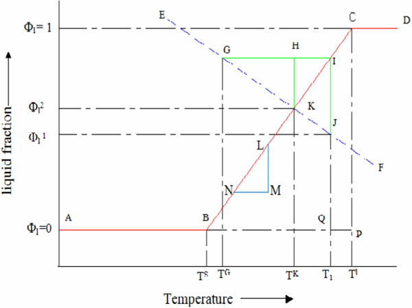
Schematic diagram of temperature correction scheme
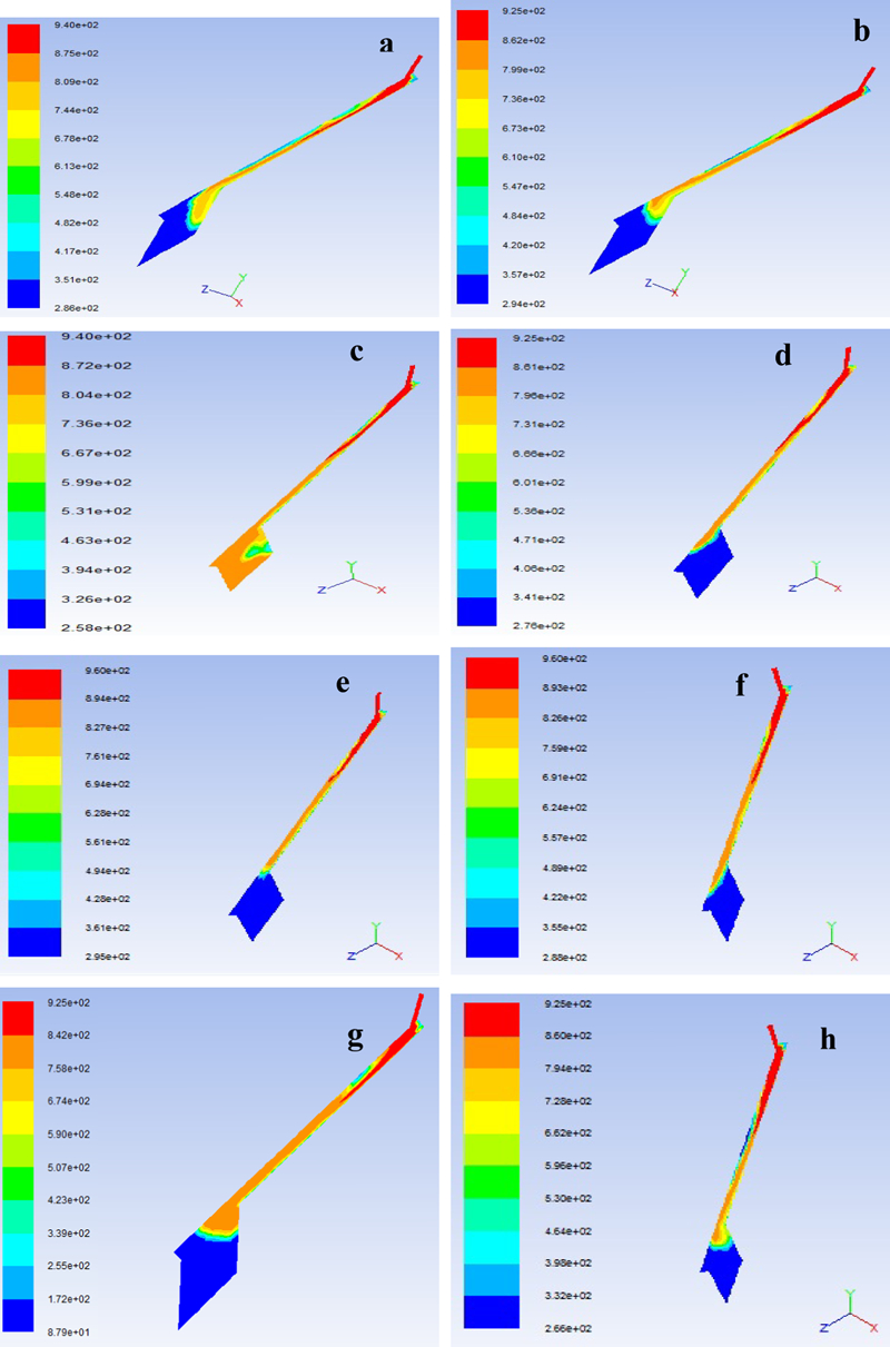
Temperature profile for a experiment 4, b experiment 8, c experiment 3, d experiment 5, e experiment 1, f experiment 2, g experiment 6 and h experiment 7
Effect of slope angle
Cooling slope tilt angle has a significant effect on the thermodynamic state of the semisolid slurry. With all other process variables fixed, the exit temperature observed in case of 45° slope angle is less than that with 60° slope angle. The comparison of phase profile is shown in Fig. 6. It is observed that the exit solid fraction is higher in case of 45° slope angle. The melt velocity is found to be less in case of 45° slope angle, which has a notable effect on shear undergone by the melt while flowing down the slope.
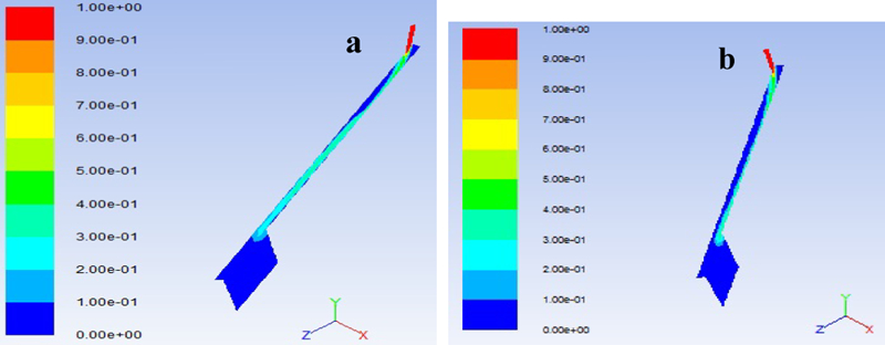
Phase profile for a experiment 5 and b experiment 7
Effect of cooling slope wall temperature
Wall temperature of the cooling slope affects nucleation of the primary phase, which in turn influences slurry temperature and solid fraction at the exit of the slope. In the present work, the effect of wall temperature has been studied, keeping pouring temperature fixed at 925 K and using slope angles of 45 and 60°. Lower wall temperature of 333 K not only yields higher solid fraction but also affects the shape and size of the primary phase, as observed experimentally. The basic phenomenon involved in cooling slope semisolid slurry generation technique is heterogeneous wall nucleation and shearing of the solidifying melt. Wall temperature of the slope affects both the phenomenon mentioned above.
Primarily, lower wall temperature accelerates the nucleation, which in turn helps to obtain the desired solid fraction at the slope exit. As higher solid fraction leads to higher viscosity of the melt, the melt velocity is less in case of lower wall temperature. With pouring temperature of 925 K and slope angle 60°, the melt velocities at the three positions on the slope (entry, middle and exit) with a wall temperature of 423 K are 1·32, 1·9 and 2·32 m s−1 respectively, which are clearly higher compared to those with 333 K wall temperature. The corresponding comparisons of temperature and phase profiles are shown in Figs. 5 and 6 respectively.
Conclusions from numerical studies
Out of eight different case studies performed, experiment 7 is identified to be having the most favourable processing conditions for cooling slope slurry generation. The maximum solid fraction obtained is 0·44, and the corresponding exit temperature is 860 K. The exit temperature of slurry is also sufficiently above eutectic temperature of 848 K, which is favourable for further processing of the semisolid slurry.28 The results of temperature and solid fraction of the semisolid slurry at the exit of the slope, for eight different experimental conditions, are broadly divided into two plots (based on angle of the slope) and shown in Fig. 7. Figure 8 shows the temperature and solid fraction variation of the melt along slope length for both the slope angles under consideration at 925 K pouring temperature and 333 K slope wall temperature.
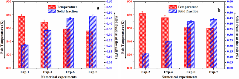
Comparative plots of temperature and solid fraction of slurry at exit of slope (experimental conditions may be seen from Table 2)
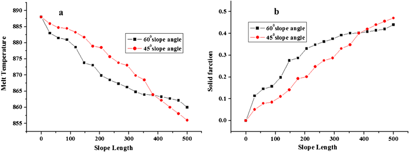
Comparative plots of temperature and solid fraction of melt along slope length for experiments 5 and 7 (Table 2)
Experimental results
Microstructural characterisation
Experimental validation is carried out for some chosen cases from the set of numerical studies. Microstructural studies are performed using optical microscopy, as shown in Fig. 9. The microstructural features observed in the rheocast billets of the said alloy, processed through the cooling slope, are remarkably different compared to that of the starting ingot. The primary phase morphology has transformed completely into a non-dendritic one in the case of rheocast ingot. Comparison has also been made with the optical micrograph of the ingot produced by directly pouring low superheat melt (10 K superheat) into a metallic mould made of mild steel. Dendritic structure is observed in the latter case, as expected. However, dendrites are generally of small size (Fig. 9a), perhaps because of the turbulence created during direct pouring.
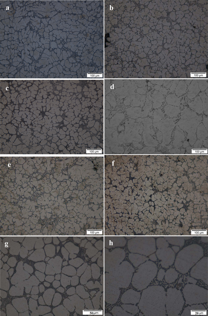
Optical micrographs at different processing conditions (experimental conditions may be seen from Table 2)
The tilt angle of the cooling slope affects not only the slurry temperature and solid fraction at the exit of the slope but also the microstructural morphology of the solidified melt. The melt flow inertia decreases and also the cooling time increases with decreasing slope angle. In the present work, the effect of 45 and 60° slope angles is studied. The primary phase morphology is more spherical in case of 60° slope angle. Agglomerations of the primary particles are observed in case of rheocast billets, processed through 45° slope angle, which may be due to reduced shear of the solidifying melt during flow. The relevant optical micrographs are shown in Fig. 9b and c.
Higher melt pouring temperature into the slope affects the microstructural morphology in a negative manner. With more superheat, the required cooling time for initiation of nucleation increases, resulting in less residence time for the α-Al primary particles to globularise. Figure 9d and e (corresponding to pouring temperatures of 960 and 940 K respectively) depicts more dendritic and rosette structure of the primary phase, as compared to the globular microstructure with a pouring temperature of 925 K (Fig. 9c).
Wall temperature of 333 K is found to give the best results among the experiments performed with 60° slope angle. Further decrease in wall temperature causes remnant material in the slope due to premature solidification of the melt. Increase in wall temperature causes less shear during melt flow, which helps the primary phase to form agglomeration and reduces sphericity of the particles (Fig. 9f).
Among the experiments performed, we find that a pouring temperature of 925 K with 60° slope angle and 333 K wall temperature yields the best microstructure having maximum degree of sphericity of the primary α-Al phase and lowest grain size. The microstructure of the solidified billets processed according to the ideal condition is shown in Fig. 9c. Optical image revealed nearly spherical grains and needle shaped eutectic silicon particles. Figure 9g and h shows the morphology of the primary Al and eutectic Si at higher magnifications (×50 and ×100).
Temperature measurements
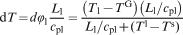
Figure 10 shows the temperature versus flow time plot obtained from thermocouples. Three K type thermocouples (TC1, 2 and 3) are placed along flow length of the melt stream to measure the melt temperature and to estimate the solid fraction present in it, at different locations of the cooling slope. For the best condition of 925 K pouring temperature with 60° slope angle and 333 K wall temperature, TC3 shows the melt stream temperature of 862 K at the exit of the cooling slope, which is in good agreement with the numerically obtained value of 860 K (obtained in case of numerical experiment 7). Figure 11 shows the comparative plot of numerical and experimental findings of exit temperature and solid fraction of the semisolid slurry for two different processing conditions. The results show that the numerical model slightly underpredicts the slurry temperature at the exit of the slope, which in turn ensures the overprediction of the solid fraction as it has been extrapolated from the temperature values using Schiel's model (shown in equation (13)).
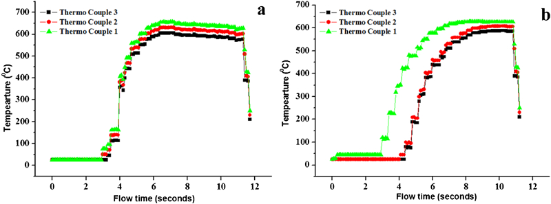
Experimentally obtained temperature versus flow time plot during melt flow through cooling slope
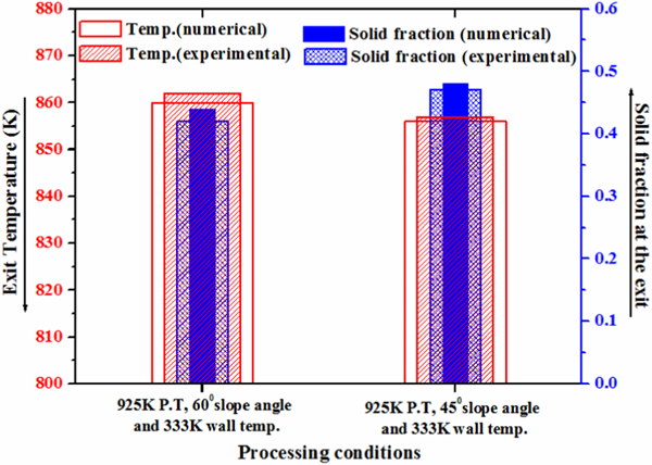
Comparative plot of numerical and experimental findings
Figure 10 confirms the faster temperature drop of the melt in case of 60° slope angle due to higher velocity of travel of the melt. Faster loss of melt superheat also explains the reason of enhanced globularity of the primary phase, in case of 60° slope angle compared to that of 45° slope due to availability of more shearing time during melt flow through the slope.
Image analysis
For calculating the size and sphericity of the primary phase, two parameters, such as grain diameter and shape factor, are measured using standard image analysis software ImageJ. Grain diameter GD and shape factor SF are calculated according to the following equations2,7


It may be noted here that each globule is treated as a separate grain. For optimum SSP characteristics, the shape factor should be as close to 1 as possible. The error on shape factor and grain size measurements is about ±2% (shown using error bars in Fig. 12). Maximum degree of sphericity (0·75) and minimum grain size (38 μm) of the primary α-Al have been obtained from the solidified castings, processed using the ideal condition corresponding to experiment 7 (as mentioned above in the section on ‘Temperature measurements’).
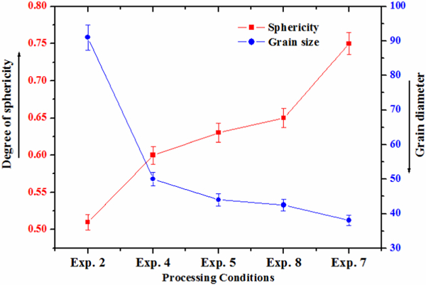
Grain size and degree of sphericity of primary particles
To distinguish between the primary phase formed during passing through the cooling slope and formed by the following growth in the mould, melt sample has been collected from the exit of the slope and readily quenched in oil. Figure 13a shows the micrograph of the slurry sample, collected from the exit of the slope. Figure 13b shows the micrograph of the solidified rheocast billet, processed according to the best processing condition found in the present work.
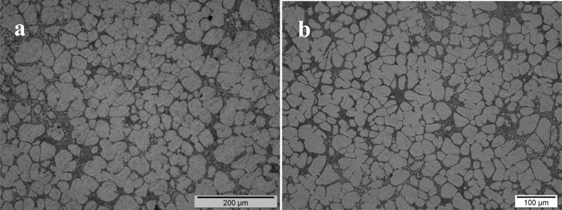
Optical micrograph at ideal processing condition of 60° slope angle, 925 K pouring temperature and 333 K wall temperature
Rheocast billets shows lesser area fraction of eutectic Si phase (Fig. 13b), due to equilibrium solidification, compared to that of quenched semisolid slurry sample (Fig. 13a). However, the micrographs confirm the contribution of cooling slope in the spheroidisation of primary α-Al phase due to the reasons explained earlier. The growth of the primary phase during solidification in the mould (after passing through the cooling slope) has been observed up to some extent from the micrographs, but no profound effect on degree of sphericity of the primary phase is seen.
Conclusions
The present study reports modelling, simulation and experimental validation of semisolid slurry preparation of A356 aluminium alloy using a cooling slope. Numerical model of the cooling slope semisolid generation technique has been developed using Eulerian two-phase flow approach. Eight sets of numerical simulations have been carried out to reveal the effect of some key process variables such as pouring temperature, tilt angle and wall temperature of the slope on the state of the semisolid slurry. Out of the case studies performed, the best processing condition has been identified as 60° slope angle, 925 K pouring temperature and 333 K slope wall temperature. These processing conditions result in a solid fraction of 0·42, slurry temperature of 862 K at the exit of the slope, maximum degree of sphericity of 0·75 and minimum grain size of 38 μm of the primary α-Al phase, evaluated experimentally. The experimental results are in close agreement with the corresponding predicted data using the present numerical model. Microstructure obtained from the best processing condition reveals globular grains and finer eutectic silicon particles within a well defined boundary.
Footnotes
Acknowledgements
The authors would like to thank DST, New Delhi, for their financial support to the present work. The authors express their heartfelt gratitude to Dr G. Biswas, Director, CSIR-CMERI, Durgapur, for his continuous encouragement and all the members of Foundry group, especially Mr B. R. K. Venkatapathi, Mr T. Roy and Mr J. Bindhani, for their cooperation for the successful completion of the present research work.