
Abstract
Specimens of 20 cold worked alloy D9 and 316LN were tested for self-welding susceptibility in flowing sodium at 823 K. A contact stress of 24·5 MPa was maintained during the test, and tests were carried out for two different durations of 3 and 4·5 months for each. It was found that susceptibility to self-welding in flowing sodium is higher for cold worked alloy D9 than for cold worked 316LN. This is in contrast with no self-welding reported for annealed alloy D9 and high susceptibility to self-welding reported for annealed austenitic stainless steels like 316LN, 321 and 304. Dynamic recrystallisation of the cold worked structure at the location of self-welding, which does not occur for cold worked 316LN steel, is the reason attributed to the high susceptibility of cold worked alloy D9 to self-welding. It appears that carburisation of cold worked alloy surface, which leads to the formation of coarse TiC precipitates at the surfaces, assists dynamic recrystallisation.
Introduction
The prototype fast breeder reactor, which is under construction in India, uses 316LN as structural material and alloy D9 as wrapper and clad tube material in fuel subassemblies of the reactor core. The alloy D9 is 20 cold worked to reduce void swelling, which can occur in austenitic stainless steels under irradiation. Minimum contact area between the fuel subassemblies is set by providing wrapper pads on each of the six faces of the hexagonal wrapper. Owing to heat and radiation induced swelling during reactor operation, there is a possibility that the fuel subassemblies are bent against any of the adjacent subassemblies, and wrapper pad to wrapper pad contact is established. High contact stresses, high operating temperatures (823 K) and long duration (typical resident time of fuel subassemblies inside the reactor is ∼2 years) of contact can lead to self-welding of the wrapper pads of adjacent wrappers at the location of contact. If this happens, extra force has to be provided by the fuel handling machine to break the self-welding during refueling. Hence, it is important to ensure that the chances of self-welding of the fuel subassemblies at the location of the pads do not exist in the reactor operating condition.
Self-welding is a diffusion bonding phenomenon that occurs when two virgin metallic surfaces are pressed against each other for a sufficiently long duration at high temperature. During this process, deformation of the surfaces in contact takes place due to loading, and during the subsequent recovery and recrystallisation that follow, diffusion of atoms takes place across the contact interface, resulting in self-welding of the mating surfaces.1 Liquid sodium in inert environment removes the oxide films that would normally be present on the metallic surfaces and thus facilitates self-welding. The self-welding coefficient W, defined as the shear stress for breakaway per unit contact stress, has been used to compare the susceptibility of various combinations of the material to self-welding. This coefficient is found to be proportional to the square root of the test duration t of the self-welding test in sodium.2
Self-welding experiments have been carried out on different austenitic stainless steel material combinations. Yokota and Shimoyashiki,2 Huber and Mattes,3 Yoshida et al.4 and Agostini and Masetti5 studied the susceptibility of 304, 316 and 321 austenitic stainless steel, and our team studied the self-welding of alloy D9 and 316LN austenitic stainless steels.6–8 It was observed in the previous studies that under identical conditions of testing, the mating surfaces of annealed alloy D9 did not exhibit self-welding, while the mating surfaces of annealed 316LN specimens self-welded. Further, testing of cold worked alloy D9 specimens revealed that self-welding does occur in the cold worked condition, though the experimental conditions in which these tests were carried out simulate conditions more severe than what is expected during reactor (prototype fast breeder reactor) operation. Hence, the present study on the self-welding susceptibility of cold worked 316LN stainless steel in flowing sodium was carried out. In the present paper, the results obtained are presented and compared with those obtained for cold worked alloy D9. The variations observed in the self-welding susceptibility of these two steels are explained based on the hardness, microstructure and recrystallisation behaviour.
Test facility for self-welding
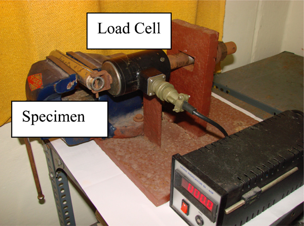
Schematics of the test set-up for evaluating the susceptibility to self-welding, specimens and their assembly are shown in Figs. 1 and 2 respectively. The set-up is provided with a rod, outer tube, disc spring, nut, load cell and provision to hold the specimens at the bottom. The specimens for studying the self-welding susceptibility are hollow cylinders of 21·4 mm outer diameter, 15·8 mm inner diameter and 15 mm height. The top and bottom surfaces of the hollow cylindrical specimens are the mating surfaces for the test. In some specimens, the top contact area is reduced by providing a step to increase the contact stress. Figure 2a shows one of the specimens with a step, and Fig. 2b shows the assembly of specimens. The contact pressure is applied by tightening disc springs at the top. The load cell is connected to the mechanism to measure the applied compressive load. The surface roughness of the contact area is maintained at <0·5 μm. The specimens are introduced into the test vessel and are filled with sodium to a level that would keep the specimens immersed in sodium. The test vessel is also connected to a sodium loop so that there is continuous flow of sodium without disturbing the level of sodium in the vessel. The sodium loop is provided with a purification facility so that the reactor grade purity (99·95 pure) is maintained for flowing sodium with oxygen concentration of <2 ppm and carbon content of <20 ppm. The sodium temperature is maintained at 823 K with sodium flowrate of 2 L min−1, and the sodium loop is operated continuously until the experiment is completed. After the completion of the test, specimens that are self-welded were separated using a mechanism as shown in Fig. 3. This mechanism consists of mechanical vice, bolt nut, disc springs and load cell, using which the breakaway force required to separate the self-welded specimens can be measured.7,8
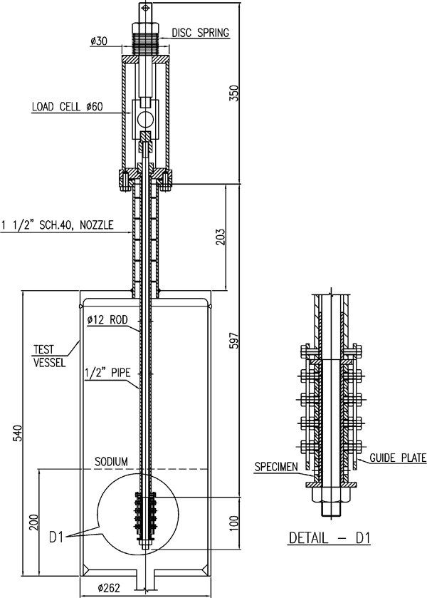
Sodium test vessel
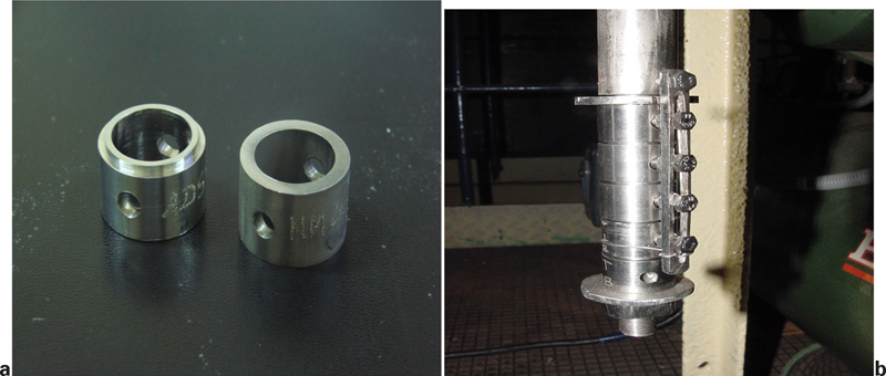
Specimen assembly for insertion into sodium vessel
Experimental
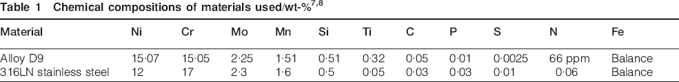
The compositions of alloy D9 and 316LN are shown in Table 1. Tests were conducted using alloy D9 and 316LN in 20 cold worked condition. For imparting cold work, alloy D9 and 316LN rods, which were in the solution annealed condition (solution annealing was carried out by heating to 1323 K for 30 min and cooling to room temperature in still air), were pulled in the tensile testing machine at room temperature at a constant rate until the area of the cross-section of the rod was reduced by 20.
Specimens were assembled and introduced into the vessel with an initial gap of 1–2 mm between the specimens. Sodium flows in the test vessel and specimens were immersed in flowing sodium. Sodium temperature was maintained at 823 K. Pure sodium reacted with the mating surfaces and removed the oxide layer, and pure metal surface was exposed. Subsequently, the specimens were compressed by tightening the disc spring. The experiment was carried out for durations of 3 and 4·5 months. After the experiment, the sodium was drained, the test vessel was cooled to room temperature and the specimens were removed from the sodium loop for examination. For specimens that were self-welded, the shear force to separate the specimens was measured.
The microstructure of the specimens before and after the testing was examined after electrolytically etching the specimens using 10 oxalic acid. The hardness of the specimens before and after the test was measured using a Vickers hardness tester, and a Vickers microhardness tester was used to get the hardness profile below the sodium exposed mating surfaces of the specimen. For microstructural examination of the specimens after self-welding susceptibility test, metallographic specimens were extracted from the testpieces, as detailed in Fig. 4. The microstructure of the cold worked alloy D9 specimens at location close to the self-welding was examined using SEM–energy dispersive spectroscopy (EDS) to identify the type of precipitates formed during the long duration of high temperature exposure to flowing sodium.
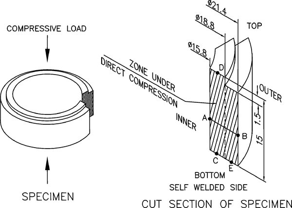
Cut section of self-welded 20 cold worked 316LN specimen for metallographic analysis
Results and discussion
Hardness and microstructure of specimens before testing
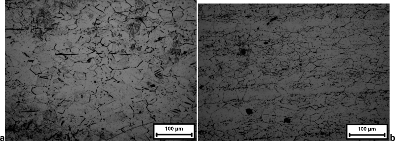
The average hardness values of 20 cold worked alloy D9 and 316LN stainless steel are found to be 238 and 265 Vickers hardness number (VHN) respectively. These are significantly higher than the hardness values obtained for the annealed alloy D9 and 316LN (134 and 145 VHN respectively). Figure 5 shows the microstructure of alloy D9 and 316LN after 20 cold work. Heavy twinning, which is typical of cold worked austenitic stainless steel, is clear in both materials.
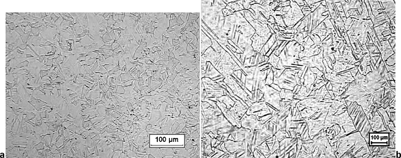
Microstructure of specimens before self-welding susceptibility studies in flowing sodium at 823 K
Comparison of experimental results of alloy D9 and 316LN
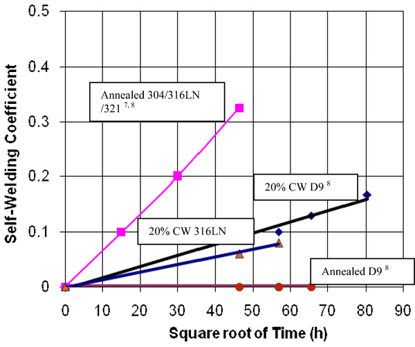
Results of the self-welding susceptibility tests are summarised in Tables 2 and 3. The breakaway force for the self-welded pairs increased with the increase in the duration of the test. Variation in self-welding coefficient with the increase in time of testing is shown in Fig. 6. It also contains results of the previous tests conducted on annealed 316LN, annealed alloy D9, 20 cold worked alloy D9 and those reported for 304 and 321 stainless steels. It is interesting to note that for all the materials that got self-welded during testing, the self-welding coefficient increased linearly with the square root of the duration of testing. Further, it is clear from the figure that cold worked 316LN steel is more resistant to self-welding than annealed 316LN and cold worked alloy D9. In contrast to the response of 316LN steel, which showed a decrease in self-welding susceptibility when subjected to cold work, cold working made alloy D9 susceptible to self-welding in flowing sodium. Annealed alloy D9 showed the maximum resistance to self-welding in flowing sodium at 823 K.
Self-welding susceptibility of alloy D9 and 316LN in sodium at 823 K
Results of self-welding tests of cold worked 316LN in sodium at 823 K
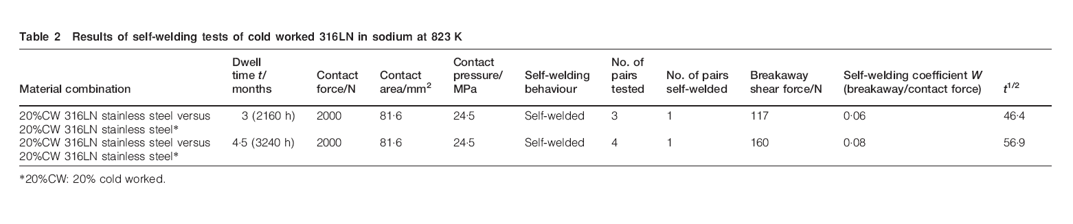
*20CW: 20 cold worked.
Results of self-welding tests of cold worked alloy D9 in sodium at 823 K (Ref. 8)
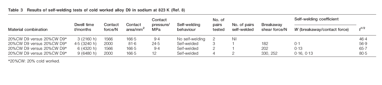
*20CW: 20 cold worked.
The relation between self-welding coefficient and duration of test was first reported by Yokota and Shimoyashiki,2 and the results of our tests carried out using annealed and cold worked 316LN and alloy D9 also confirm this relation. Self-welding occurs at the asperities present on the specimen surfaces where the surfaces are in contact. The increase in self-welding coefficient with duration of test is due to the surface roughness of the mating surfaces where the actual contact area of the asperities (higher in size) in the initial stage is less. As the duration of the test increases, deformation at the asperities increases the areas of the mating surfaces, and also, additional asperities (lower in size) come in contact facilitating self-welding in more areas. Thus, with the increase in test duration, the breakaway shear stress required to separate the self-welded surfaces also increases.
Hardness and microstructure examinations
Since the susceptibility of cold worked alloy D9 and 316LN steel to self-welding in flowing sodium was found to be significantly different, detailed hardness measurements and microstructure examinations were carried out. The hardness of the test specimens was measured after the completion of the tests, and the results of this measurement along with hardness of the annealed and cold worked specimens before the tests are shown in Table 4. It was found that the hardness of 316LN in both annealed and cold worked conditions showed a slight decrease after the test, while the hardness of alloy D9 increased slightly after the test. However, the report indicated that prolonged exposure of the cold worked alloy at 823 K did not result in any hardness change due to the high temperature exposure of the materials (not in flowing sodium) during the test.9 The marginal increase in hardness of the D9 alloy in high temperature flowing sodium could be due to TiC precipitating in this alloy and in the early stage of formation of this carbide; the precipitation hardening effect could be contributing to the hardness of the alloy. It is also to be noted that ∼20 ppm of carbon is present as impurity in sodium. Based on the hardness of the specimens after the test, cold worked alloy D9 is expected to have the maximum resistance to self-welding. However, the results obtained are not in agreement with this.
Hardness before and after self-welding tests/VHN
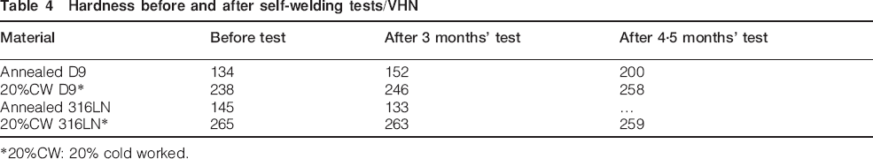
*20CW: 20 cold worked.
The microstructures of the cold worked alloy D9 and 316LN after prolonged exposure to high temperature flowing sodium after the test are shown in Fig. 7. There is a significant reduction in the twin boundaries, and there is no evidence of recrystallisation of the cold worked structure in both steels. This is in agreement with the marginal change in hardness observed on the specimens after the test.
Microstructure specimens after self-welding susceptibility studies in flowing sodium at 823 K after 4·5 months
The microstructure of the materials at the location of self-welding was compared with that of the materials in a similar location of the specimen where there was no self-welding. For this purpose, metallography samples were extracted from the self-welded test specimens, as described in Fig. 4. In this sample, locations marked C and D are in direct contact with the test specimen and thus experience direct loading during the self-welding susceptibility test. The location marked C corresponds to the location of self-welding. In contrast, location E is not in contact with the specimen and does not experience direct loading. AB is the thickness of the specimen. The microstructures of the specimen at locations C and E for cold worked alloy D9 are shown in Fig. 8a. Below location C (self-welded), significant recrystallisation of the cold worked structure has taken place for several micrometres of depth in cold worked alloy D9. At location E for cold worked alloy D9, there is no recrystallisation. Hence, it is attributed to the dynamic recrystallisation taking place under the influence of stress acting on cold worked alloy D9.
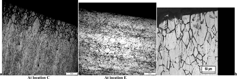
Microstructure just below location of self-welding of 20 cold worked a alloy D9 and b 316LN after 4·5 months in 823 K flowing sodium at 24·5 MPa contact pressure
In contrast, in cold worked 316LN, no such recrystallisation is observed at C or E as shown in Fig. 8b. No change in microstructure is observed with distance from the location of self-welding along the depth. This indicates that there is no dynamic recrystallisation in cold worked 316LN. This could be the reason for better resistance of the former to self-welding than the cold worked alloy D9.
Microhardness measurement at C, D and E
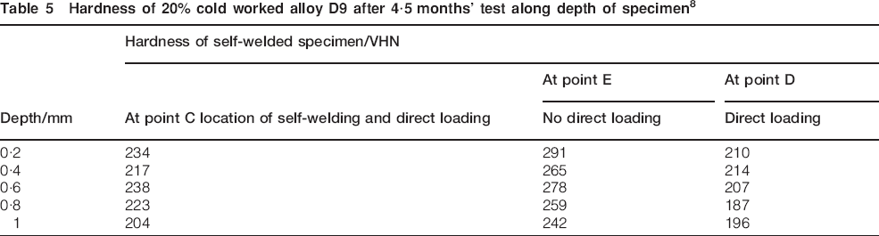
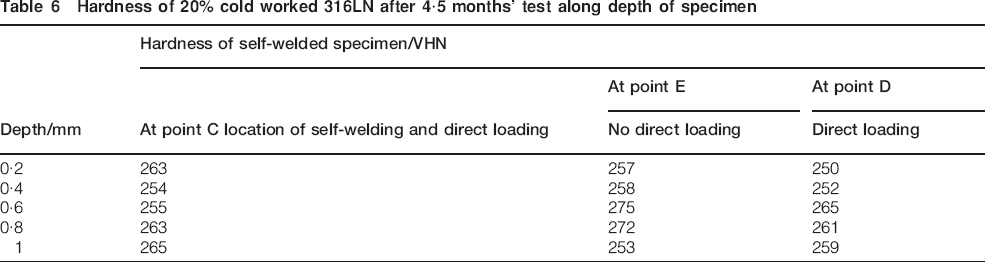
The microstructural change observed is also in line with the hardness variations at locations C, D and E as measured using the microhardness tester, which are shown for cold worked alloy D9 and cold worked 316LN in Tables 5 and 6 respectively. It is clear that the hardness for a depth of 1 mm just below locations C and D is much lower than that at location E for cold worked alloy D9 (Table 5). At location C, it is in the range of 200–240 VHN; at location D, it is in the range of 190–215 VHN; and at location E, it is in the range of 240–290 VHN. The hardness measured at location below E is close to the bulk hardness of 258 VHN for cold worked alloy D9 reported in Table 4. In contrast, there is no specific change in hardness for locations C, D and E for cold worked 316LN. For all the three locations, the hardness measured is in a narrow range of 250–275 VHN, which conforms to the bulk hardness of 259 VHN reported for cold worked 316LN after the test (Table 4).
Hardness of 20 cold worked alloy D9 after 4·5 months’ test along depth of specimen8
Hardness of 20 cold worked 316LN after 4·5 months’ test along depth of specimen
Dynamic recrystallisation in cold worked alloy D9
From the results presented above, it can be concluded that the dynamic recrystallisation that takes place in cold worked alloy D9 just below the mating surface is the reason for the higher susceptibility to self-welding than the cold worked 316LN. The reason for proposing that the recrystallisation is dynamic is that it takes place when both stress and temperature act together. Normal recrystallisation occurs in the presence of high temperature exposure alone. Hardness and microstructural changes are also confined only to the location just below the stressed part of the surfaces where self-welding has taken place. In the case of normal recovery and recrystallisation, hardness reduction and microstructural changes should have taken place throughout the test specimens. Further, recovery and recrystallisation studies carried out on alloy D9 at higher temperatures indicate that recrystallisation does not take place in the cold worked alloy D9 at 823 K, the temperature of testing in the present study.9 It should also be noted that though the nominal stress applied for self-welding susceptibility is low (24·5 MPa), the actual stress at the points of contacts of the mating surfaces (asperities present on the surfaces) would be high enough for dynamic recrystallisation to occur.
Precipitation of TiC in cold worked alloy D9
Though alloy D9 and 316LN are austenitic stainless steels with almost similar composition in alloy content, there is a significant change in the dynamic recrystallisation behaviour subjected to identical cold work. Hence, literature available on the recrystallisation behaviour of alloy D9 was critically reviewed, and it was found that the recrystallisation in alloy D9 is influenced by the presence of coarse TiC particles.10 Ti is an alloying element only in alloy D9 and not in 316LN, and the composition of the alloy D9 is designed to facilitate the formation of fine TiC precipitates. However, prolonged exposure of alloy D9 to flowing sodium results in pickup of carbon from liquid sodium and precipitation of TiC close to the surface. Hence, carburisation of the alloy D9 surface by flowing sodium could lead to the formation of TiC near the surface, and this precipitate can in turn facilitate recrystallisation in cold worked alloy D9 during self-welding. To identify coarse TiC precipitates, SEM–EDS analysis was carried out on the self-welded part of the metallographic sample extracted from the cold worked alloy D9 specimen, which corresponds to location C in Fig. 4. Figure 9 shows the SEM image along with the EDS spectra from two grain boundary carbides marked M and N in the micrograph. The precipitate marked M, which appears to be fairly coarse and a few micrometres in size, is rich in Ti, indicating precipitation of TiC in cold worked alloy D9.
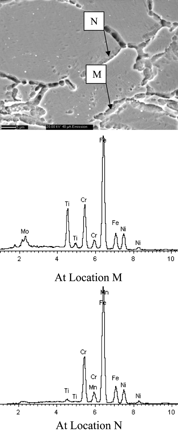
Scanning electron microscopy–EDS of 20 cold worked alloy D9 after 4·5 months in 823 K flowing sodium at 24·5 MPa contact pressure
Conditions favouring self-welding in cold worked alloy D9
Thus, based on the facts that Ti is an alloying element present only in alloy D9, carburisation of the cold worked alloy D9 surface by flowing sodium can indeed lead to the precipitation of TiC at grain boundaries and coarse TiC precipitates can accelerate recrystallisation in alloy D9, it can be concluded that the high susceptibility of cold worked alloy D9 mating surfaces to self-welding in flowing sodium is due to the dynamic recrystallisation of the cold worked structure, which is assisted by the presence of coarse TiC precipitates. In annealed D9, there is no recrystallisation of cold worked microstructure; hence, carburisation of the surface by flowing sodium alone does not facilitate self-welding, and it is resistant to self-welding.
It is unlikely that TiC precipitates would be present in the alloy before the start of the test as it is solution annealed and subsequently cold worked. However, while testing is in progress, the carburisation of the alloy D9 by the flowing sodium can result in the formation of TiC, and dynamic recrystallisation can occur subsequently. This would mean that there could be an incubation time for self-welding to occur. In this context, it may be noted that cold worked alloy D9 did not self-weld in the test duration of 3 months.8 Microstructural examination of this sample also did not reveal any evidence of dynamic recrystallisation, as coarse TiC was not available to facilitate dynamic crystallisation in the short duration test. Another important aspect is the role of carburisation of the alloy D9 by flowing sodium. If carbon in liquid sodium is nil, then carburisation of the specimen surface by flowing sodium may not take place, and this also can indirectly prevent self-welding.
Conclusions
The major conclusions from the present study are the following.
The self-welding susceptibility of cold worked alloy D9 is more than that of cold worked 316LN in flowing sodium. Though annealed alloy D9 does not self-weld, annealed 316LN is highly susceptible to self-welding.
Dynamic recrystallisation of cold worked alloy D9 just below the surfaces that are under stress is the reason for the high self-welding susceptibility of cold worked alloy D9. Dynamic recrystallisation is not observed in cold worked 316LN specimens under identical conditions of testing.
Carburisation of the surface by flowing sodium, which leads to the precipitation of TiC at the grain boundaries, facilitates dynamic recrystallisation and thus self-welding in cold worked alloy D9.
Footnotes
Acknowledgements
The authors acknowledge and thank the directors of the Metallurgy & Materials Group and the Fast Reactor Technology Group, Indira Gandhi Centre for Atomic Research, Kalpakkam, India, for the support provided in carrying out the present study.