
Abstract
Annealed and quenched M50NiL steel specimens were plasma nitrided at 460°C for 4 h under a mixture gaseous supply of 0·05N2+0·4H2 L min−1 to investigate the effects of the substrate microstructure on the features of nitrided layer, such as microstructure, microhardness and wear resistance. The results show that the nitrided layer is mainly consisted of α′-Fe, γ′-Fe4N and α′N (nitrogen expanded martensite) phases. The surface hardness is significantly enhanced. For the quenched specimens, the nitrided depth decreases with increasing quenched temperature. Compared to the quenched specimens, the nitrided depth of the annealed specimen is thicker under the same nitriding condition. The mechanism may be the variation in the amounts of interstitial carbon atoms and substitution alloying elements in the lattice, and the compressive residual stresses in the substrate. It is also demonstrated that the wear resistance for both the annealed and the quenched specimens can be significantly improved by plasma nitriding treatment.
Introduction
The material used in the present investigation is M50NiL martensitic steel, which is a new generation bearing steel with the combination of strength and fracture toughness. 1 However, untreated M50NiL steel exhibits low hardness and poor tribological properties for use in severe conditions, such as high operation temperature, heavy loads and high speed. 2 Accordingly, surface treatment is indispensable for the practical application of M50NiL steel.
Plasma nitriding is a thermochemical surface treatment involving the introduction of nitrogen into the surface layer of steel by glow discharge at low temperature. This method enjoys many advantages. For example, it produces a modified layer with little deformation, high surface hardness, high fatigue, good wear and corrosion resistances.3–7 The relationship between the mechanical properties and the nitriding condition is the most important factor for design of surface strengthening steels. Aydin et al. 8 applied plasma, salt bath and gas nitriding treatments to AISI 304 type austenitic and AISI 420 type martensitic stainless steels. They concluded that plasma nitriding was the most effective surface treatment to improve the surface hardness and the wear resistance of these steels. Results obtained by Menthe et al. 9 showed that plasma nitriding significantly increased the hardness of the nitrided case and strongly reduced the wear rate of austenitic stainless steel. Research conducted by Tang et al. 10 showed that a composite structure (includes a compound layer and a diffusion layer) with high hardness was formed after plasma nitriding, which could provide considerable improvement in the wear resistance of 30CrMnSiA steel. However, the compound layer composed of brittle nitrides such as ϵ-Fe2–3N could increase the wear rate of the specimen and decrease the toughness of elastic components.11,12
The microstructure and mechanical properties of the plasma nitrided layer depend not only on the experimental parameters (such as nitriding temperature, atmosphere, time and pressure) but also on the content of alloy elements and initial microstructures. 13 On the one hand, controlling these governing factors can tailor the concentration of the free alloying elements and the compressive residual stresses in the substrate. On the other hand, it can influence the diffusion of nitrogen atoms during plasma nitriding. Thus, the hardness, phase composition, microstructure, layer thickness and mechanical properties of the nitrided layers can be improved.
Nevertheless, fundamental understanding of the plasma nitriding behaviour of M50NiL steel is seldom reported. In the present work, the plasma nitriding treatment of M50NiL steel was carried out to investigate the effects of the initial microstructure on the microstructure, phase structure, microhardness and wear properties of the nitrided layer.
Experimental
Materials
The as received M50NiL steel with the chemical composition of Fe–0·13C–4·06Cr–3·26Ni–3·78Mo–1·25V–0·30Mn–0·12Si–0·012P–0·002S (wt-%) was used. The specimens were divided into two groups for use of annealed and quenched treatments. The annealed specimens were indicated as group A, and the quenched specimens were indicated as group Q. The specimens for quenched treatments were first treated at temperatures of 980 and 1150°C for 1 h respectively and then quenched in oil. The quenched specimens were marked as Q980 and Q1150, wherein the subscript stands for the quenched temperature. Before plasma nitriding, specimens were machined into 10×10×4 mm, 11×11×4 mm and 12×12×4 mm for specimens of A, Q980 and Q1150, and then the flat faces of the specimens were manually ground with SiC abrasive papers from 240 to 800 grade.
Plasma treatment
Plasma nitriding was performed in a LDMC-30t plasma nitriding unit. The plasma nitriding furnace chamber was evacuated to below 10 Pa by a rotary pump before the application of the glow discharge. Plasma nitriding was conducted at 460°C for 4 h in mixed gases of nitrogen and hydrogen with flow rates of 0·05 and 0·4 L min−1. After nitriding, the specimens were cooled down slowly in the furnace chamber under the protection of nitrogen to avoid surface oxidation. The annealed specimens and the quenched specimens after plasma nitriding were marked as A-N, Q980-N and Q1150-N respectively.
Characterisation
The morphologies and microstructures of the un-nitrided and nitrided cross-sections of the specimens were observed under an optical microscope (CMM-33E). The phase compositions of the nitrided surface were analysed using the X-ray diffraction (XRD, type D/max-rB) with Cu Kα radiation (λ = 0·15406 nm) in the range of angles 20–100° at 40 kV and 30 mA with 0·05° interval step mode. Microhardness profiles of the nitrided layers were measured by a Vickers microhardness tester (HV-1000) under a load of 100 g for 15 s.
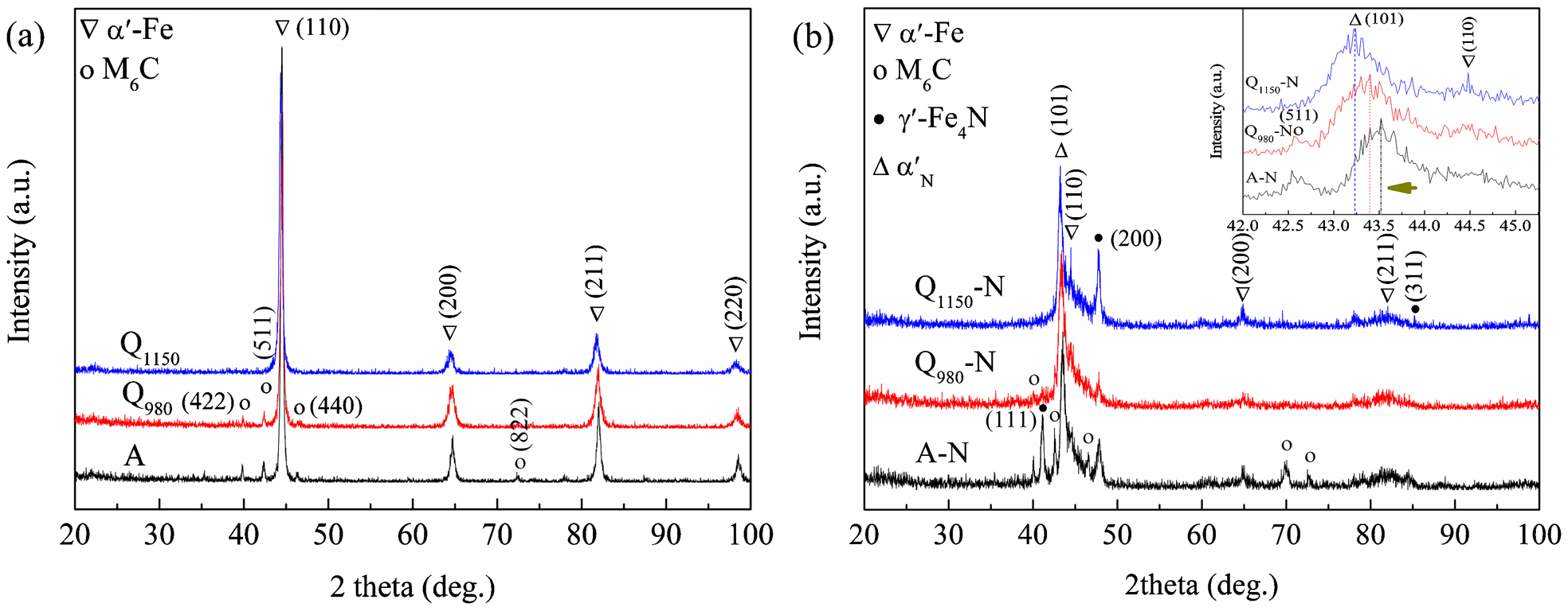
The dry wear properties of the specimens were evaluated using a pin on disc apparatus (Teer POD-I). The main feature of the test rig was that the stationary pin was mounted vertically against the horizontal specimen, which was moved by a rotating table. It was point contact between the pin and the surface of the specimen. During the test, M50NiL steel specimen was rotated against the stationary WC ball (2000 HV0·1) of 5 mm diameter at the speed of 200 rev min−1 for 3600 s under contact load of 10 N. The circle diameter of the wear track was ∼8 mm. The friction coefficients were continuously recorded during the test by a computer. All tests were performed in air (temperature, 20°C; humidity, 50% relative humidity). After wear tests, the worn mass ΔM was weighed by a precision electronic balance (FA2204B) with an accuracy of 0·0001 g. Mass wear rate η was calculated according to the following equation
Results and discussion
Microstructure observation
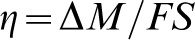
Figure 1 shows the initial microstructures of M50NiL steel specimens before nitriding. The microstructure of the annealed specimen consists of dispersed alloy carbides and ferrite (Fig. 1a), and its hardness is 264 HV0·1. The specimen Q980 exhibits martensitic structure with a few undissolved alloy carbides (Fig. 1b), and its hardness is 430 HV0·1. Because the specimen Q980 was heated at 980°C, below the complete austenitising temperature, alloy carbides were not fully dissolved. The specimen Q1150 is complete martensite (Fig. 1c) with hardness of 436 HV0·1.
Micrographs of substrate microstructures of a A specimen, b Q980 specimen and c Q1150 specimen
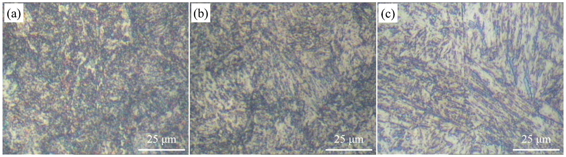
The nitrided layers are shown in Fig. 2. It can be seen that the plasma nitrided layer includes only the diffusion layer without conventional compound layer. Evaluation of the nitrided layer depths of the nitrided specimens reveals that the layer thickness of the annealed specimen is thicker than the quenched specimens. The dominating factor is the nitrogen mass transfer during plasma nitriding process.14–16 In the present work, since the specimens were nitrided in the same batch (under the same nitriding conditions), the nitrogen incorporation of the substrate surface can be considered identical before the formation of nitrides. Therefore, the difference in the nitrided layer depth and mass gain should be caused by the nitrogen mass transport process inside the substrate. The factors that can affect the nitrogen transport process might be substrate composition, residual stresses and nitrogen diffusion coefficient. 15
Typical cross-sectional morphologies of a A-N specimen, b Q980-N specimen and c Q1150-N specimen
Phase analysis
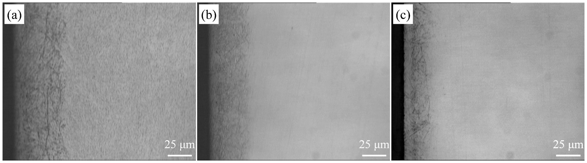
Figure 3 shows the XRD patterns of the specimens before and after plasma nitriding. From Fig. 3a, the annealed specimen shows the peaks of the ferrite and M6C (M6C may be complex carbides that are formed from carbide forming elements like Cr, Mo and V) phases. The specimen Q980 shows martensite and undissolved alloy carbide M6C phases. The specimen Q1150 is complete martensite phase (α′-Fe).
X-ray diffraction patterns of surface layers of a un-nitrided specimens and b nitrided specimens
After plasma nitriding, the phases of the Q980-N and Q1150-N specimens (Fig. 3b) are mainly composed of γ′-Fe4N, martensite (α′-Fe) and nitrogen expended martensite ( ), but there is still a little M6C phase in the surface layer of the specimen Q980-N. The formed
  phase is due to the supersaturated nitrogen in the body centred cubic (bcc) martensite lattice.17,18 The inset of Fig. 3b shows that the main diffraction peak is split into
  (101) and α′-Fe (110) lines. In addition, the
  (101) line is shifted to lower angle compared to the α′-Fe (110) line. The reason may be the incorporation of nitrogen into the α′-Fe lattice, which presumably leads to the expansion of c axis of the bcc lattice. It is also shown that the shifted extent of the
  (101) line towards low diffraction angle increases with the increase in the pretreatment temperature, indicating the increase in nitrogen content in the surface layer. Moreover, the relative peak intensity ratios of
  to
to  for specimens Q980-N and Q1150-N are found to be 16 and 30% respectively. It is obviously demonstrated that high pretreatment temperature can increase the phase proportion of γ′-Fe4N during plasma nitriding. Compared with the Q980-N specimen, the surface layer of the A-N specimen contains the same phases, but the relative intensities are different. In this case, the relative good corrosion resistance of the specimen Q1150-N derives mainly from the existence of the stable
  phase and more proportion of the γ′-Fe4N phase.
19
phase and more proportion of the γ′-Fe4N phase.
19
It is also observed that the peaks of  are broadened, indicating high residual stresses produced in the nitrided layer. The high residual stresses are attributed to the following four factors:
the volume expansion due to the solution of nitrogen in the iron lattice
the precipitation of nitrides inside the steel matrix
the non-uniform thermal stresses due to the difference in elastic constants
the different thermal expansion coefficients between the substrate and the nitrided layer.
X-ray diffraction examination and microstructure observation of the annealed and quenched specimens demonstrate that the steel matrix exhibits significant effects on nitriding behaviour. For the annealed specimen, it has lower amount of interstitial carbon atoms and substitutional alloy atoms in its bcc-α-lattice, which can be associated with the lowest residual stresses after the annealing treatment. However, for the quenched specimens, the majority of interstitial carbon atoms and substitutional alloy atoms remain inside the body centred tetragonal martensite lattice (bct-α-lattice), associating with high residual stresses. The reason for the reduction of the nitrided layer depth could be due to the high amount of interstitial carbon atoms and substitutional alloy elements inside the bct-α-lattice, and the high level of compressive residual stresses in the substrate. Since interstitial carbon atoms occupy the interstitial positions of the bct-α-lattice, the available number of interstitial sites for nitrogen is reduced. 20 The substitutional alloying elements in the bct-α-lattice can trap nitrogen atoms and facilitate nitrides to precipitate during nitriding process, leading to lower nitrogen diffusion coefficient.21,22 Compressive residual stresses can be generated after quenching, which could retard nitrogen diffusion from the surface to the core.23,24 Since the direction of compressive residual stresses is parallel to the surface after quenching, the atomic distance in direction perpendicular to the specimen surface is reduced. In this case, nitrogen diffusion from the surface to the core is hindered, corresponding to the reduction of the nitrided depth.
As mentioned above, the annealed specimen A has lower amount of interstitial carbon atoms and substitution alloying elements, as well as lower level of compressive residual stresses than the quenched specimens, so the nitrided layer depth is thicker. Similarly, the nitrided layer depth of the partially quenched specimen Q980 is thicker than the specimen Q1150-N.
Hardness
The microhardness profiles in surface layers of plasma nitrided M50NiL steel are shown in Fig. 4. The surface microhardness of the nitrided M50NiL steel is more than 1100 HV0·1, which is about five times of the annealed specimen (264 HV0·1) and three times of the 1150°C quenched specimen (436 HV0·1), so plasma nitriding can significantly increase the surface microhardness. It can also be seen that the core hardness of the specimens is different due to the different hardness of the substrate. The Q980-N specimen shows better microhardness profile in surface layer than other specimens.
Microhardness profiles in surface layers of a A-N specimen, b Q980-N specimen and c Q1150-N specimen
Wear properties
The friction coefficient versus sliding time curves of the un-nitrided and nitrided M50NiL steel specimens are shown in Fig. 5. The friction coefficients of the un-nitrided specimens immediately increase to a peak value between 0·5 and 0·6 in the early stage and then gradually decrease to a stable value. The surface hardness between the un-nitrided specimens and the counter WC ball varies widely, so the contact area is easily adhered, which leads to the increase in friction coefficient in the early stage. During sliding process, the produced small pieces of oxides perform a self-lubricating role, leading to the reduction of the friction coefficient. Moreover, in the initial stage, the friction coefficients of the un-nitrided specimens exhibit a severe oscillation, which may be caused by the breakaway of thin and unsteady oxides. In the stable stage, the oxide films are probably quite thick and steady, which are not easily broken away, so the friction coefficient is relatively low and steady. 25
Friction coefficients of un-nitrided and nitrided specimens sliding with WC ball under load 10 N for 3600 s
Compared with the un-nitrided specimens, the evolution of friction coefficients of the nitrided specimens can be divided into a gradually increasing stage followed by a stable stage. The friction coefficient of the gradually increasing stage can be decreased remarkably by plasma nitriding. In addition, the friction coefficient increases with the increase in the pretreatment temperature. Since the surface hardness (Fig. 4) of the nitrided specimens is almost the same, the main factor that influences the friction coefficient is the phase composition and proportion, i.e. the phases of γ′-Fe4N and  . According to the study of Yan et al.,
26
γ′-Fe4N is a hard nitride that can serve as abrasive particles in the wear process and aggravate the abrasion wear behaviour. As mentioned above, the relative peak intensity ratio of Iγ′(200) to
. According to the study of Yan et al.,
26
γ′-Fe4N is a hard nitride that can serve as abrasive particles in the wear process and aggravate the abrasion wear behaviour. As mentioned above, the relative peak intensity ratio of Iγ′(200) to  for specimen Q1150-N is higher than specimen Q980-N, so the friction coefficient of the Q1150-N specimen is higher.
For further characterising the wear properties, the wear rates of the un-nitrided and nitrided M50NiL steel specimens were detected and calculated by equation (1). The results are shown in Fig. 6. For specimens A, Q980 and Q1150, the wear rates can be decreased to a factor of 94·6% (from 2·42 to 0·13 mg N−1 km−1), 90·6% (from 1·06 to 0·10 mg N−1 km−1) and 86·0% (from 0·93 to 0·13 mg N−1 km−1) by plasma nitriding respectively. Owing to the higher surface hardness and lower surface roughness after plasma nitriding, the wear rates of surface layers can be significantly decreased.
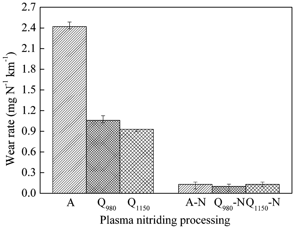
Wear rates of un-nitrided and nitrided specimens sliding with WC ball under 10 N for 3600 s
The SEM images of the wear tracks of the un-nitrided and nitrided M50NiL steel specimens are shown in Fig. 7. It is observed that the wear track width of specimen A (Fig. 7a) is ∼1·12 mm, indicating a severe plastic deformation with many fatigue cracks and spalling notches. Meanwhile, the high concentrations of wolfram and oxygen elements are found in area A (Fig. 7a and g), which indicates that the severe adhesive and oxidative wear occurred. The wear track widths of specimens Q980 and Q1150 are ∼0·88 and 0·82 mm (Fig. 7b and c), also exhibiting the fatigue and adhesive wear. But the wear degree is reduced.
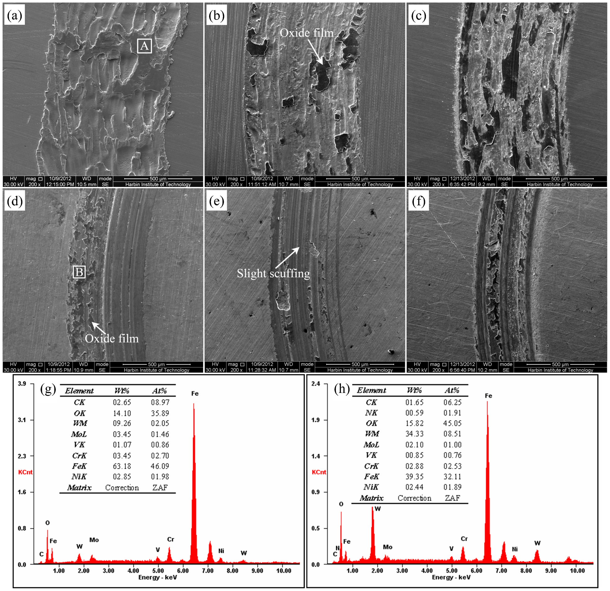
Images (SEM) of wear tracks of a A specimen, b Q980 specimen, c Q1150 specimen, d A-N specimen, e Q980-N specimen and f Q1150-N specimen after sliding with WC ball under load 10 N for 3600 s, and EDS analysis in g area A and h area B
The wear tracks of the nitrided specimens A-N, Q980-N and Q1150-N are shown in Fig. 7d–f, showing that the wear tracks widths are decreased to 0·57, 0·51 and 0·48 mm respectively. Compared with the un-nitrided specimen, the wear resistance is significantly improved. The worn surfaces only show some parallel abrasion grooves and oxidation without obvious signs of plastic deformation. The EDS analysis in area B (Fig. 7d and h) also implies the oxidation and material transference. In comparison with the friction coefficients, wear rates and the widths of wear tracks, plasma nitriding can significantly improve the wear resistance of the steel. The specimen Q980-N exhibits higher wear resistance than the others.
Conclusions
In the present investigation, the M50NiL steel specimens with different initial microstructures were nitrided at low temperature, and then the microstructure, phase structure, microhardness and wear properties of nitrided layers were investigated. The main conclusions of this research are as follows.
Before nitriding, three batches of M50NiL steel specimens were annealed and quenched at 980 and 1150°C, which resulted in dispersed alloy carbides in the ferrite matrix, martensite with a few undissolved alloy carbides and fully martensite respectively.
The plasma nitrided layer includes only the diffusion layer without conventional compound layer. The formed phases in surface layers of the M50NiL steel specimens plasma nitrided at 460°C include mainly α′-Fe, γ′-Fe4N and  phases.
The surface microhardness of the M50NiL steel specimens plasma nitrided at 460°C is more than 1100 HV0·1, which is about five times of the annealed specimen (264 HV0·1) and three times of the quenched specimen (436 HV0·1)
The nitrided layer depth for the 1150°C quenched specimen is lower than the 980°C quenched specimen and the annealed specimen. It can be interpreted that the 1150°C quenched specimen contains more interstitial carbon atoms and substitutional alloying elements in the bct-α-lattice, and higher level of compressive residual stresses, which reduces the nitrogen diffusion coefficient.
The wear resistance of the M50NiL steel specimen plasma nitrided at 460°C can be significantly improved. The friction coefficients and wear rates of the nitrided specimens are lower than the un-nitrided ones.
Footnotes
Acknowledgements
The authors gratefully acknowledge the National Natural Science Foundation of China (grant no. 51371070) and NSAF (grant no. 11176011) for the financial support of this research work.