






Abstract
Stress corrosion cracking (SCC) behaviours of Z3CN20-09M stainless steel in high temperature water containing Cl− were studied. The results indicated that SCC sensitivity was inconsistent with test temperature. The minimum and maximum of SCC sensitivity occurred at 320 and 290°C respectively, and SCC sensitivity at 250°C fell between them. SCC crack initiated preferentially at bottom of corrosion pit or along phase boundary between austenite and ferrite, and its propagation depended on relative orientation to the phase boundary. SCC crack parallel to the phase boundary propagated along the phase boundary, while that perpendicular to the phase boundary was hindered to propagate.
Keywords
Introduction
Austenitic stainless steel (ASS), which has been known for its high strength, good toughness and outstanding character of anti-corrosion, is widely used in nuclear power station components, so it is necessary to pay much attention to the stress corrosion cracking (SCC) behaviours of ASS in the high temperature water environment. Usually the SCC rarely happens in austenitic stainless steel at room temperature, but easily happens when the material exposures to corrosive environment after a long time.1–3 Temperature has always been considered as an important factor of material service and safety, especially for SCC problems in the light water reactor (LWR) environments.4–10 Normally, many researches’ results indicate that the SCC sensitivity increases with temperature in both hydrogenated and oxygenated high temperature water.11–16 For example, Arioka et al.11,12 found that the crack growth rate (CGR) of cold worked 316 stainless steels increased with temperature in hydrogenated high temperature water. Andresen et al.13,15 also found the same relationship between IGSCC sensitivity and temperature in high temperature pure water in the temperature range of 290–340°C. Lu got a quite accurate curve that describes the CGR increased with temperature from 200 to 288°C. 16 However, some disordered relationship between temperature and SCC behaviours are sometimes found. It was reported that sensitised stainless steels showed a much different character with increase of temperature. In the temperature range of 200–300°C, a peak of CGR versus temperature appeared at 250°C.6,17–19 Asakura found a corrosion rate peak at 260°C in the temperature range of 200–300°C using impedance analysis techniques for AISI 304 stainless steel in high temperature water. 20 The above researches do reveal that the relationship between temperature and SCC behaviours is rather complicated, which is not understood up to now.
Former studies also showed that the effect of boundaries and second phases (including ferrite) to crack propagation.21–23 Z3CN20-09M stainless steel, which contains a certain amount of ferrite (more than that in 304SS, less than that in duplex stainless steels), is usually fabricated as primary coolant pipe in nuclear power plants. Some researches have been carried out on Z3CN20-09M stainless steel,24–27 however few of them refers SCC behaviours. This work focuses on SCC behaviours of Z3CN20-09M stainless steel in high temperature water, especially on effect of test temperature on SCC behaviours.
Material and experimental procedure
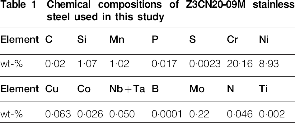
The materials in this study were cut from a nuclear grade stainless steel (Z3CN20-09M) pipe which is used as PWR's primary loop, and subsequently solution annealed at 1050°C for 2 h to reduce the effect of carbide. The chemical composition is listed in Table 1. To observe the microstructure, it was electrochemical etched using 10% oxalic acid at 6 V for 30 s. Figure 1 is its optical microstructure, which shows different shapes of ferrite distributes in austenitic base. From Fig. 1 the ferrite amount was estimated to be 18·03% in volume by IMAGE PRO PLUS.

Optical microstructure of Z3CN20-09M stainless steel
Chemical compositions of Z3CN20-09M stainless steel used in this study
A strip sample with a size of 75×15×2 mm was prepared, and its surface was mechanically polished. After that, an electronic universal testing machine was used to deform the sample into U-bend shape at a speed of 0·2 mm s−1. Then the U bend specimen was ultrasonic cleaned in acetone and ethanol successively, and finally dried in the air. In order to make clear the stress distribution of U-bend specimen, a finite element analysis (FEA) ANSYS method was used. During FEA a double linear isotropic hardening model was used. Density, elasticity modulus and nuxy used in FEA were 7·57 g cm−3, 193 GPa and 0·3 respectively.
The U bend specimens were hanged on a stainless steel rack in a SS316 autoclave with a C276 inner lining. High temperature ceramics washers (see Fig. 2) were used for insulation between the specimens and the rack. All the specimens were immersed into NaCl water solution with Cl− concentration of 100 mg L−1. Nitrogen was charged into the autoclave to make sure the inner pressure was about 15 MPa during test. The test temperature was 250, 290 and 320°C respectively at a pressure of 15 MPa, while the test duration was 120, 360 and 720 h respectively.

U-bend samples and high temperature ceramics washer for insulation
After test for each duration, a magnifier with a magnification of 15 was used to check whether the specimens were cracked. Cross-sectional morphology observation and thickness measurement of the oxide film were carried out by a SUPRA 55 field emission scanning electron microscopy (FESEM). For the specimens containing SCC cracks, SEM backscattering image technique was used to observe the cracks, phase boundaries and their relationships.
Experimental results and discussion
Stress distribution on U-bend specimen
Figure 3 shows stress distribution on the U-bend specimen. It is found that the stress maximum is not located at the top of the U-bend, however at a little distance from the top. As shown in Fig. 3, the red part in Fig. 3a shows where the tensile stress maximum is, while the blue part in Fig. 3b is the position where the compressive stress maximum is located. In general, SCC always happens because of tensile stress and some specific environment, therefore we infer that SCC will most likely take place at the red part in the U-bend specimen.

Stress distribution of U-bend samples
Macro morphology of U bend samples after test in high temperature water
Table 2 shows macro morphologies of U-bend specimens after test at different durations and temperatures in high temperature water. It is obvious that both corrosion and SCC damages are not consistent with the test temperature. It is found that colour of the specimens tested at temperature of 250 or 320°C is much darker than that of those tested at 290°C. After 720 h test, the specimens tested at 250 and 320°C becomes blacker, microcracks are found on some samples; however those tested at 290°C still show metallic luster and none of them is cracked. It is noticed that the microcrack usually nucleates at some of rusts in the maximum tensile stress area (red part in the Fig. 3), which indicates that SCC micorcracks derive from pit corrosion. On the highest compressive stress area (blue part in the ANSYS figure), no crack is found, which indicates that corrosion usually takes place in the tensile stress area, and finally results in occurrence of SCC.

Macro morphologies of U-bend samples after different test duration for different temperatures in high temperature water
Effect of temperature on SCC sensitivity
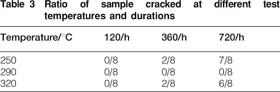
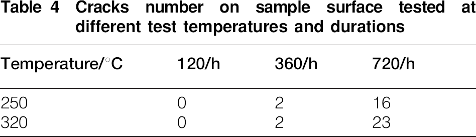
Table 3 shows number of cracked specimens to the total ones at different test temperatures for different test durations. It is found that no crack appears on the specimens after 120 h test at three temperatures. When the test duration is increased to 360 h at 250 and 320°C some tiny cracks can be seen on 25% (2/8) specimens, however there is no crack at 290°C. When the test duration is further increased to 720 h, 87·5% (7/8) specimens have cracked at 250°C, while at 320°C the ratio of cracked specimens is 75% (6/8). However, there is still no crack appeared on the specimens tested at 290°C. It is apparent that the SCC sensitivity is not consistent with test temperature. The SCC sensitivity at 250 and 320°C is much larger than that at 290°C. In order to evaluate SCC sensitivity more accurately at different temperatures, the crack number on the U-bend specimens tested at temperatures of 250 and 320°C was counted, that result is listed in Table 4. It is found that there only two cracks appeared on specimens after 360 h test at both temperatures. When the test duration is increased to 720 h, the crack number at 320°C is apparently more than that at 250°C. Therefore, the maximum of SCC sensitivity of Z3CN20-09M occurs at 320°C, while SCC hardly happens at 290°C. This study is different from many researches about stainless steels and nickel based alloys,11–16,28–30 that results can be briefly expressed as ‘higher temperature, higher SCC sensitivity’. However, other research results support this study. Their results show that sensitised 304 and 316 stainless steels showed a V-shape trend in corrosion rate and SCC behaviours in the temperature range of 200–300°C although their mechanisms were not clear up to now.6,17–20
Ratio of sample cracked at different test temperatures and durations
Cracks number on sample surface tested at different test temperatures and durations
Effect of temperature on oxide film
Figure 4 shows cross-sectional morphologies of the oxide films after different test durations at different temperatures. Figure 5 shows thickness of the corresponding oxide films. It is found that the surfaces of all samples are covered with a compact oxide film after 120 h test. The thickness of oxide films at 250 and 320°C is 0·4–0·6 μm, while that at 290°C is smaller (about 0·2 μm). With increase in test duration the oxide film becomes thicker, and gradually changes to bi-layer structure, e.g. a compact inner layer and a loose outer one, at 250 and 320°C. When the test duration is increased to 720 h, the oxide films at 250 and 320°C grow to a thickness of 1·8–2 μm. By contrast, oxide film at 290°C only grows to a thickness 0·4 μm, and still keeps a single layer in structure at 720°C. The bi-layer structure has been reported earlier,31–34 but the single layer oxidation film is the first time to be reported in high temperature water. Compared with the oxidation films formed at 250 and 320°C, it is found that the oxide film formed at 250°C shows a compact inner layer, while the inner layer formed at 320°C has ruptured. Therefore it is nationally presumed that 320°C exhibits the highest SCC sensitivity among three test temperatures, which is consistent with experimental results.

Cross-sectional morphologies of oxide films of samples after test for different temperatures and durations

Oxide film thickness at different test temperatures and durations
Nucleation and propagation of SCC cracks
Figure 6 shows SCC morphology in the cross section of cracked specimens. Figure 6a shows that the ferrite has been corroded at the position where the tensile stress maximum is located. The SCC crack initiates at the phase boundary and propagated into austenite. From Fig. 6b, it is found that SCC crack initiates at the bottom of a corrosion pit. In fact, most SCC cracks initiate at pits or along phase boundaries (see Fig. 7).

Cross-sectional morphologies of SCC samples after 250°C×360 h test

Cross-sectional morphologies of SCC samples after 320°C×360 h test
In the crack growth process, the SCC crack propagation strongly depended on the relative orientation of SCC crack to the phase boundary between austenite and ferrite. When SCC crack initiated at the phase boundary or bottom of the pits is parallel to the phase boundary, it is inclined to grow along the phase boundary, as shown in Fig. 7a and b. When SCC crack propagation is perpendicular to the phase boundary, the phase boundary hinders propagation of the SCC cracks. Some of SCC cracks change their propagation direction to along the phase boundaries, as shown in Figs. 8 and 9.

Cross-sectional morphologies of SCC samples after 250°C×720 h test

Cross-sectional morphologies of SCC samples after 320°C×720 h test
Conclusions
Stress corrosion cracking (SCC) behaviours of Z3CN20-09M stainless steel in high temperature water with Cl− at different test temperatures were studied in a static autoclave. The oxidation films, nucleation and propagation of SCC cracks were subsequently characterised. The following conclusions can be drawn.
The SCC sensitivity of Z3CN20-09M was not consistent with test temperature. The maximum of SCC sensitivity occurred at 320°C, while its minimum took place at 290°C, and the SCC sensitivity at 250°C fell between them.
Test temperature had a strong effect on the characterisation of the surface oxide film, but there was no corresponding relationship between them. At the test temperatures of 250 and 320°C, the oxide film was a bi-layer structure including a compact inner layer and a loose outer one. However, at 290°C the oxide film was a compact single layer in structure and exhibited much thinner.
SCC crack was preferential to initiate at the bottom of corrosion pit and along phase boundary between austenite and ferrite.
SCC crack growth strongly depended on the relative orientation of SCC crack and the phase boundary between austenite and ferrite. When SCC crack was parallel to the phase boundary, it was inclined to propagate along the phase boundary. When SCC crack propagated perpendicularly to the phase boundary, the phase boundary hindered propagation of the SCC cracks.
Footnotes
Acknowledgements
The work described in this paper was supported by Important National Science & Technology Specific Projects of China 2011ZX06004-009, The National Basic Research Program (973 Program) of China 2011CB610504, and The Basic Research Universities Special Fund Operations of China FRF-TP-09-030B.