
Abstract
This paper reports the results of a study into the fatigue behaviour of laser sintered Nylon 12 specimens in both reversed and rotating bending. Rotating bending tests are generally the most efficient in terms of test time, but reversed bending deformation explicitly promotes delamination, and so the main aim was to identify whether or not there was significant variation in fatigue behaviour between the two loading modes. The paper presents the first reversed bending fatigue test study on selective laser sintered Nylon parts and compares the results to fatigue behaviour from rotating bending. The results showed no significant variation in fatigue behaviour between the two loading modes and also showed an isotropic response in terms of fatigue behaviour in both test configurations.
Introduction
Selective laser sintering (SLS) is now a well established manufacturing technology with a wide range of applications ranging from medical 1 and sports 2 to automotive and aerospace. 3 Within the family of technologies described as additive manufacturing, SLS is one of the most versatile process offering higher dimensional accuracy 4 particularly compared to nozzle based polymer deposition methods, good mechanical properties 5 and overall design freedom 6 afforded by the nature of the process that requires no extra support structures and can handle internally nested parts as well as multiple objects in the same volume.
Some recent applications of SLS have been aimed at end use parts in the fields of orthotics and prosthetics7,8 where the customisation opportunities are high and the possibility of manufacturing one-off or tailor made medical devices seems a good fit. Such efforts bring associated need for a better understanding of the long term behaviour of SLS made parts, particularly ones that are meant to be used during prolonged periods in load bearing applications.
Studies on the fatigue behaviour of additively manufactured parts are still rare. For Nylon processed by SLS, van Hooreweder et al.9–11 performed uniaxial tension/compression fatigue tests with both notched and unnotched at low frequencies (3 Hz) and compared the results with injection moulded specimens; results showed an endurance limit for the additively manufactured parts of ∼18 MPa. Munguia and Dalgarno 12 observed a fatigue limit of 14 MPa for Nylon tested on a four-point rotating bending fatigue device. In both these studies, it was of note that the fatigue response was unaffected by the build orientation. Static load to failure tests on Nylon SLS parts do show an anisotropic response9,12 as a result of the layer by layer build process, but this does not seem to be reflected in the fatigue behaviour. However, neither of these studies had examined flex fatigue, and reversed bending is a loading mode, which promotes delamination.
Therefore, in order to establish that the fatigue behaviour of laser sintered Nylon was not significantly influenced by build orientation, the aim of the present study was to characterise the fatigue behaviour of Nylon SLS specimens in a flex fatigue mode. A secondary aim was to benchmark reversed bending against the generally more time efficient rotational bending fatigue testing.
Materials and methods
Specimen production
All specimens for the present study were manufactured in the same batch using SLS (EOSINT P 760; EOS GmbH, Munich, Germany) of Nylon-12 powder (PA2200; EOS GmbH, Munich, Germany). All parts were supplied by Materialise (Leuven, Belgium) and produced using their standard manufacturing procedures. In total, 40 specimens were manufactured: five for each orientation (X, Y and Z axes) for tensile and flexural fatigue and five for each of the two orientations for rotating fatigue specimens (Fig. 1).
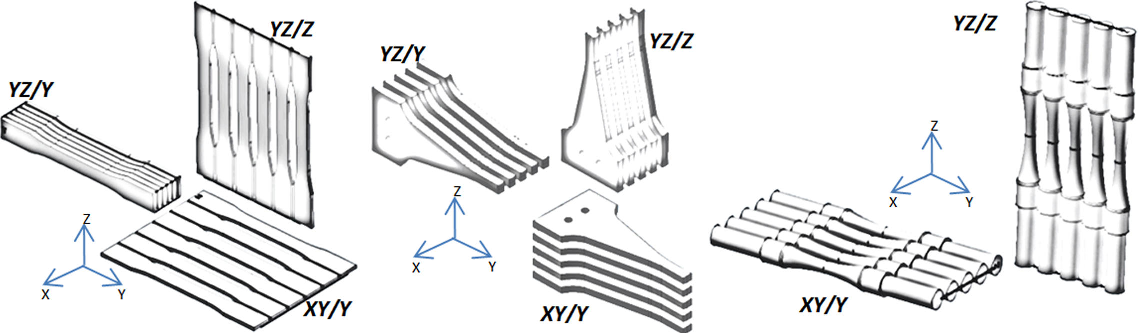
a tensile specimens, b reverse bending specimens and c rotating bending
The characteristic SLS Nylon melting and crystallisation temperatures were obtained using differential scanning calorimetry (DSC) with the following protocol: hold for 5·0 min at 30°C, heat from 30 to 300°C at 10·00°C min− 1 and hold for 5·0 min at 300°C.
Dimensions
Critical dimensions of the laser sintered specimens were measured with a Mitutoyo digital Vernier calliper and surface roughness determined using a Mitutoyo Surftest-401 surface roughness tester. Specimen weights were measured with a digital balance (KERN pfb, d = 0·001 g).
Tensile test parts (Fig. 2) were designed according to recommendations from ASTM D638, 13 whereas for both types of fatigue specimens, geometries had to be extracted and adapted from alternative references. Reversed bending fatigue geometries are based on recommendations from ASTM D671-93, 14 which include a triangular surface for a uniform force distribution. Rotating fatigue tests are normally aimed at metal specimens, so we extracted recommended geometries and dimensions from BS 3518-3:1963, which clearly define gripping areas, curvature and gauge test length.
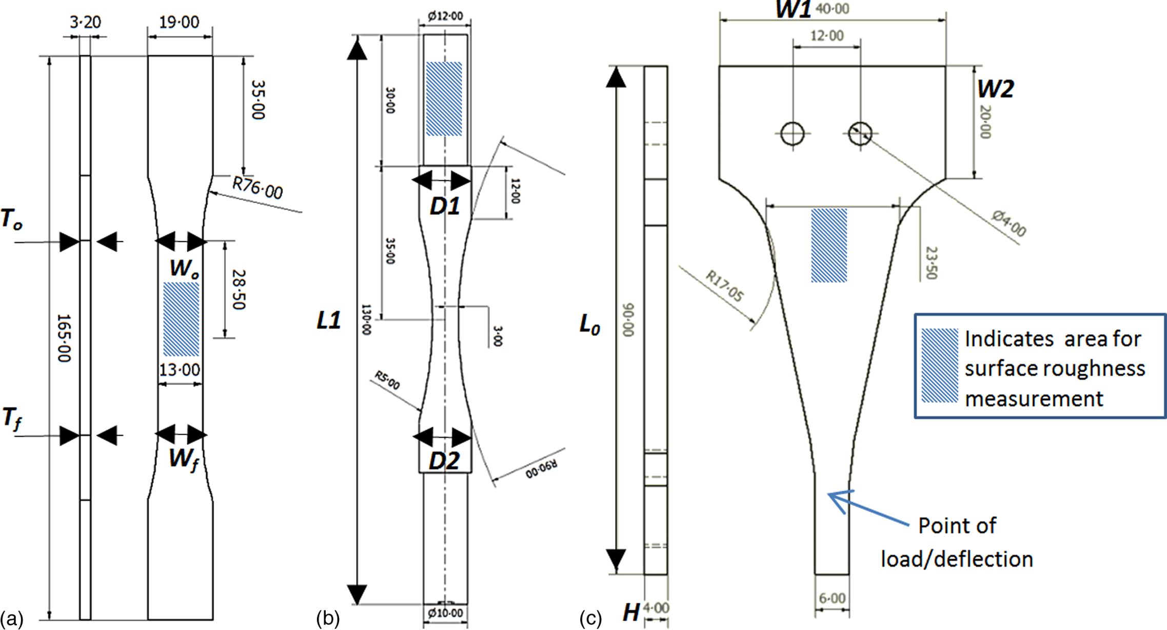
a tensile specimen, b rotating fatigue specimen and c reverse bending fatigue specimen
Experimental
Tensile tests
Tensile properties were obtained with an Instron-4505 electromechanical test system (Instron 100KN 2518 Series load cell) with 2 mm min− 1 crosshead speed, with a 2 pts/s data log capacity. The ultimate tensile strength and yield strength of tensile bars were computed in accordance with ASTM D638. 12
Rotating–bending fatigue tests
A previously developed purpose built four-point rotating fatigue rig was used, 12 where stress is induced by calibrated weights subjecting the specimen to repeated load cycles at the middle span (Fig. 3), while the specimen ends are clamped by grubs crews. The specimen's geometry follows an hour glass shape in order to take advantage of rotation and localised loading, thus inducing a constant bending moment across the whole test area. Test parameters of frequency, timing cycles and stop are fully programmable by means of a direct drive and feedback system, and the test stops immediately after the specimen fully breaks. Tests for this experiment were run at 30 Hz with effective stresses ranging from 20 to 65 MPa for each of the two build specimen orientations (XY/Y and YZ/Z).
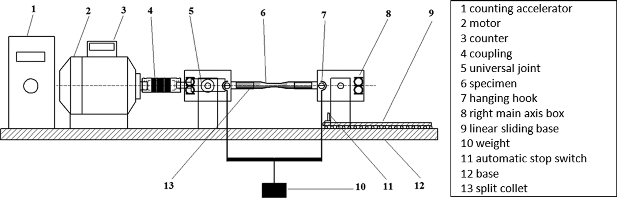
Rotating fatigue test jig schematic and its elements
Reversed bending test
A reversed bending fatigue jig was designed according to similar previous applications,15,16 which converted rotational motion into a linear displacement with variable length according to the eccentric wheel (Fig. 4). Available displacements for this set-up range from 5 to 50 mm, and they can be adjusted manually before each test. Reversed bending frequency was set at 15 Hz for all specimens. The linear movement is transferred by a shaft, which deflects the specimens by means of contact rollers (pure bending). Vibration that may cause heat build-up and unwanted stresses was reduced by calibrating the displacement of moving mechanisms and limiting their movement by the use of infrared displacement sensors.
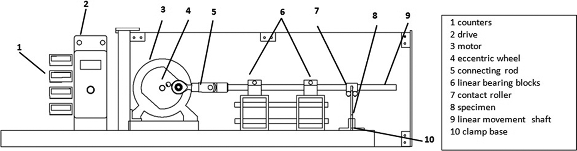
Reversed bending fatigue test jig schematic and its elements
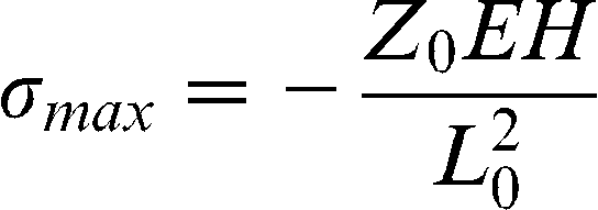
The resulting bending stresses on the triangular shape relating to the tip displacement can be estimated by equation (1), where σmax is the estimated max. stress, z0 is the deflection at the specimen's tip, E is the material's flexural modulus, H is the specimen's thickness and L0 is the overall length.
Results
Specimen characterisation
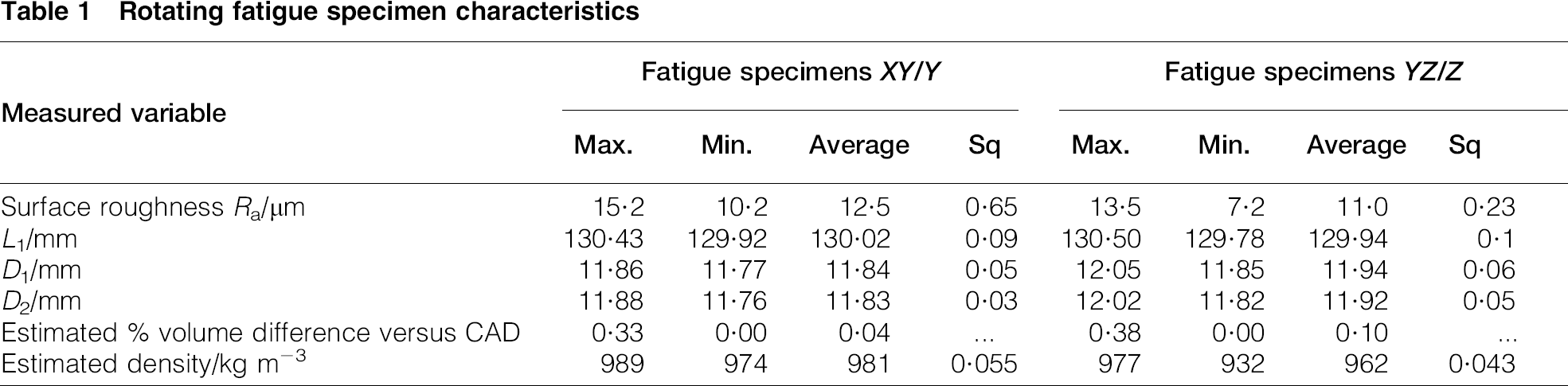
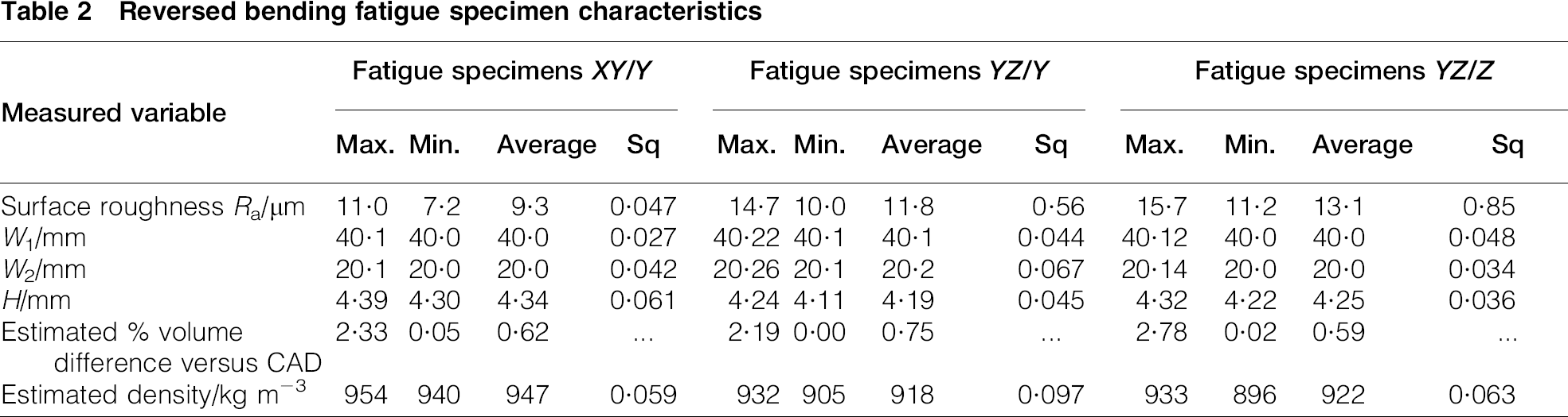
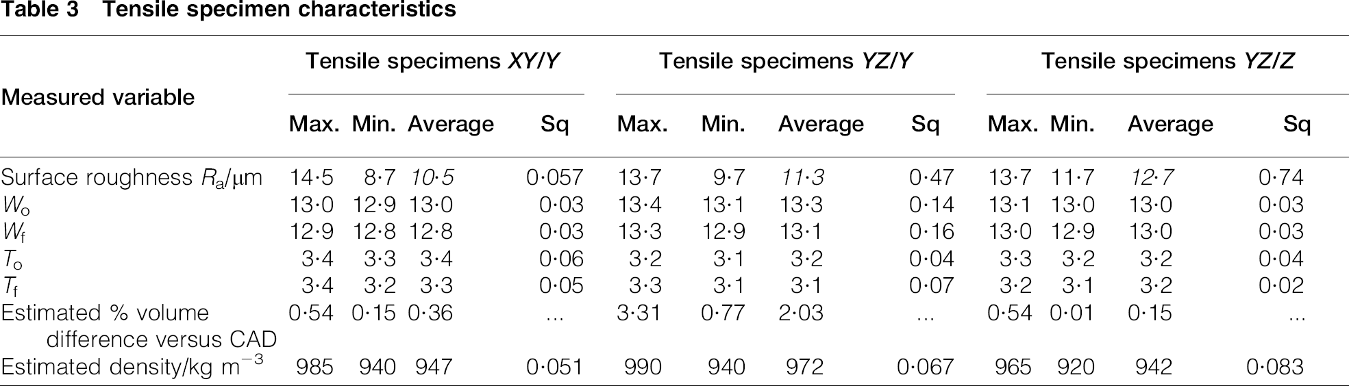
As differences can be expected between the nominal dimensions in computer aided design (CAD) and the resulting laser sintered parts, the main specimen dimensions were carefully measured in order to estimate the deviation from the original design. Density has been identified as a key indicator for specimen integrity and aptitude to be tested;9,16 therefore, it was estimated for each specimen by measuring the specimen mass and deriving the actual volume from key dimensions (L1, D1 and D2 for the rotational bending specimens; W1, W2 and H for the reversed bending specimens; and Wo, Wf, To and Tf for the tensile test specimens; as shown in Fig. 2). Results for the three sets of specimens are shown in Tables –3.
Rotating fatigue specimen characteristics
Reversed bending fatigue specimen characteristics
Tensile specimen characteristics
Thermal profile
The heat of fusion and the melting point was determined through DSC measurement PA12 in two forms: powder (unsintered) and solid (sintered sample) (Fig. 5). As PA12 is a semicrystalline polymer, the melting point is measured as the peak of the endotherm on the DSC curve characterised by a negative curve trend. The melting point for both test was placed between 190 and 205°C. Slightly lower melting temperatures were registered by van Hooreweder (186·23°C) and other studies on PA12 (Tm = 187·26°C), 10 which can be due to differences in material composition from the supplier as well as polymer age and recycling ratios; however, the results shown in Fig. 5 are broadly in line with those obtained by other researchers.
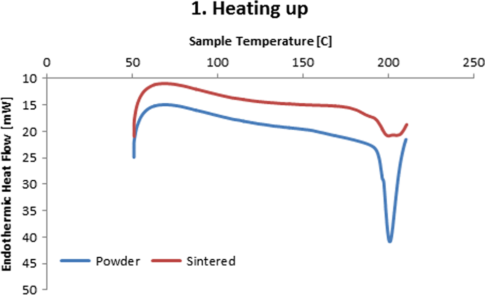
Thermogram for SLS nylon in powder and solid form obtained from DSC
Tensile test results
Figs. 6–8 show the results of the tensile tests with average values from the 15 tested specimens (five for each orientation). The results are generally consistent for the different orientations, with the exception of the elongation at break, which is much lower along the z axis. Anisotropy due to the effect of the part's orientation inside the build chamber is present in most laser sintered parts, which affects the measured properties along the three directions as identified by previous studies.12,18,19
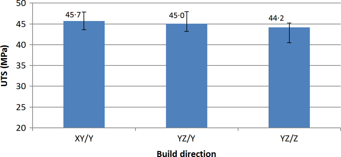
Average ultimate tensile strength with error bars showing min. and max. values versus build orientation
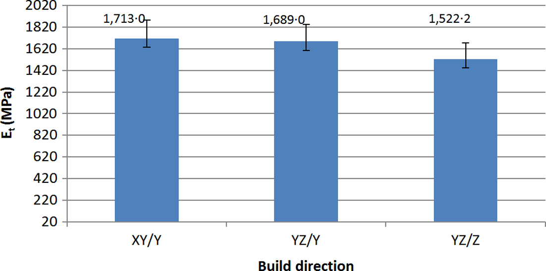
Average tensile modulus with error bars showing min. and max. values versus build orientation
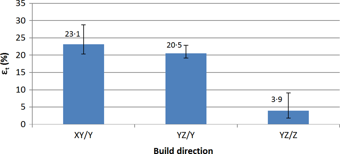
Average strain at break with error bars showing min. and max. values versus build orientation
Rotating bending fatigue test results
The rotating bending fatigue results are plotted as Wöhler curves in Fig. 9. Although there is some scatter and one significant ‘outlier’, the main observation is that there is significant overlap between the XY/Y and YZ/Z specimens.
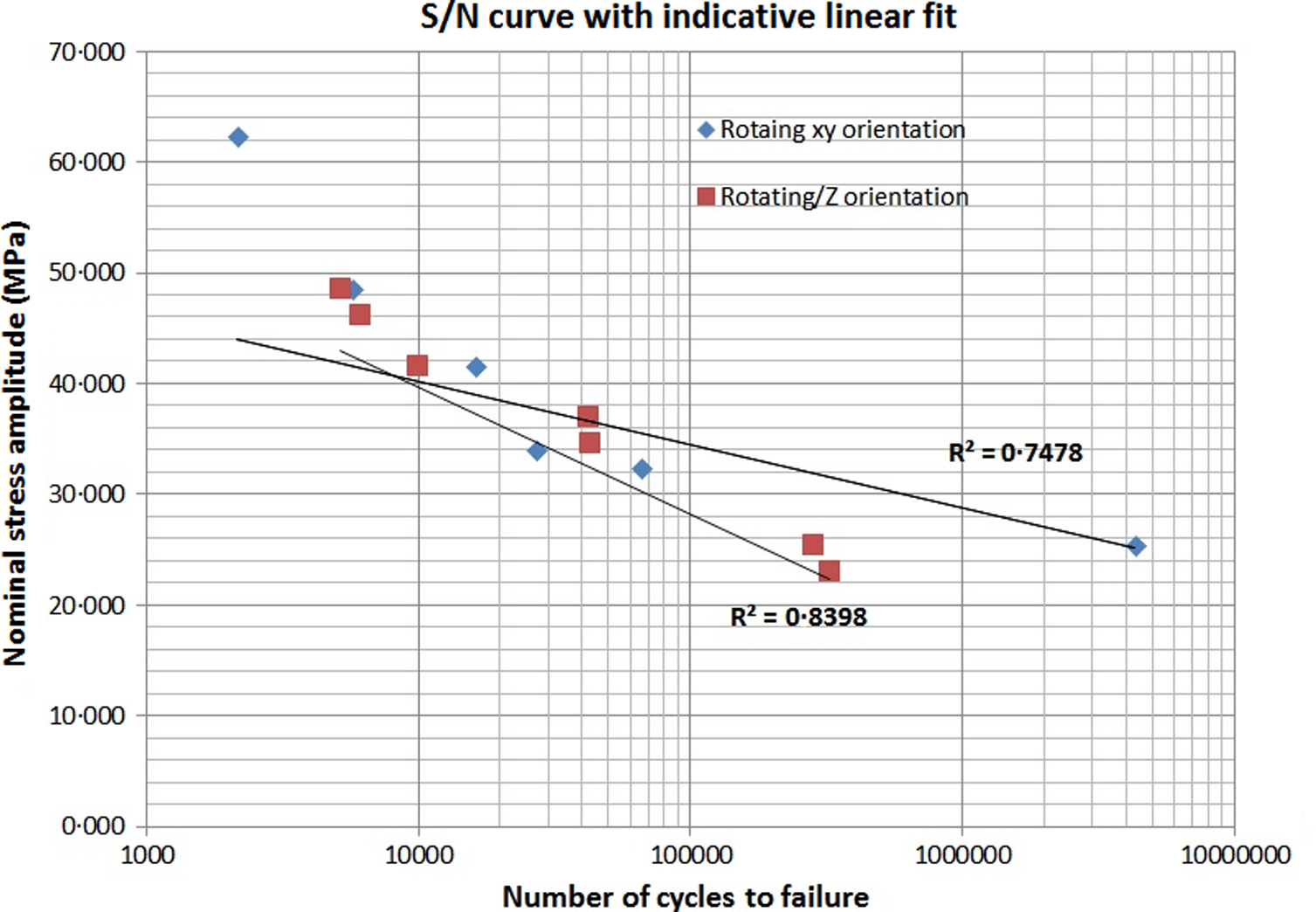
S/N curves for rotating bars built on XY/Y and YZ/Z axes and tested at 30 Hz
Reversed bending fatigue test results
The three sets of reversed bending fatigue test results for the different build directions are plotted on a semilogarithmic scale with their corresponding least squares line fit and correlation coefficients in Fig. 10. It should be noted that this fatigue test was displacement controlled rather than load controlled, and so these stresses are inferred from equation (1). Again, there is significant overlap in the results from the different orientations, and no significant anisotropy in behaviour is observed.
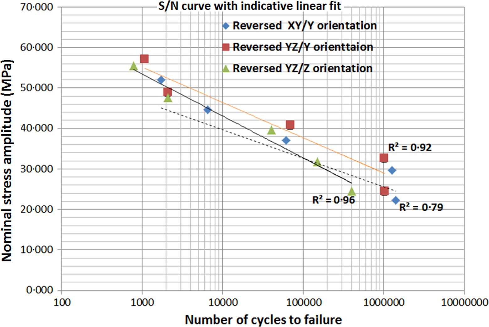
S/N curves for reversed bending beams built on XY/Y, YZ/Y and YZ/Z axes and tested at 15 Hz
Correlation between two tests
Fig. 11 shows the results of all reversed bending and rotating fatigue tests and shows that the behaviour in rotating and reversed bending is very similar regardless of the differences in bending modes. As the rotating bending induces a constant bending moment across the specimen's critical cross-section, the reversed bending regime conditions were also selected so they approximated the conditions of pure bending by adopting constant deflection on both faces and avoiding shear and mean stresses. The slopes of the regression lines are not significantly different when tested at a 95% confidence level, and so the behaviour in rotating and reversed bending can be considered to be the same. At lower stresses, it is possible that the rotating bending test is the more conservative, but further testing would be required to confirm this.
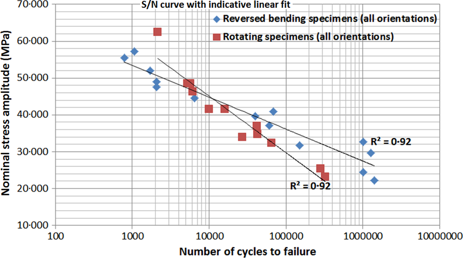
Test correlation between: rotating and reversed bending specimens in all directions
Fracture surfaces
Figs. 12 and 13 show the typical fracture surfaces for both types of fatigue tests and all orientations. XY/Y and YZ/Y reversed bending specimens present a characteristic hinge line along the middle span of the fracture area. As the highest stresses are found on the external surfaces, cracks initiate on the front and back faces and propagate towards the middle of the sample until the point at which the sample can no longer withstand the load. This line is not evident on specimens built on the YZ/Z direction, as there is a broader band through the middle of the specimen indicating where final rupture has occurred. For YZ/Z specimens, the layers are bonded parallel to the fracture surface direction, and it would seem that easier debonding can occur as a result. This change in fracture behaviour has not resulted in significantly different fatigue life, as shown by Fig. 10, suggesting that initiation of the surface cracks is the key determinant of fatigue life. No gross delamination between layers was seen in any of the reversed bend tests. Rotating bending fracture surfaces are shown on Fig. 13: there are no significant differences in the appearance of the fracture surfaces from the different orientations. As for the reversed bending specimens, fracture progresses from the outer surface (where the maximum stresses and strains are) towards the middle of the specimens, with final fracture when the effective section can no longer sustain the load.
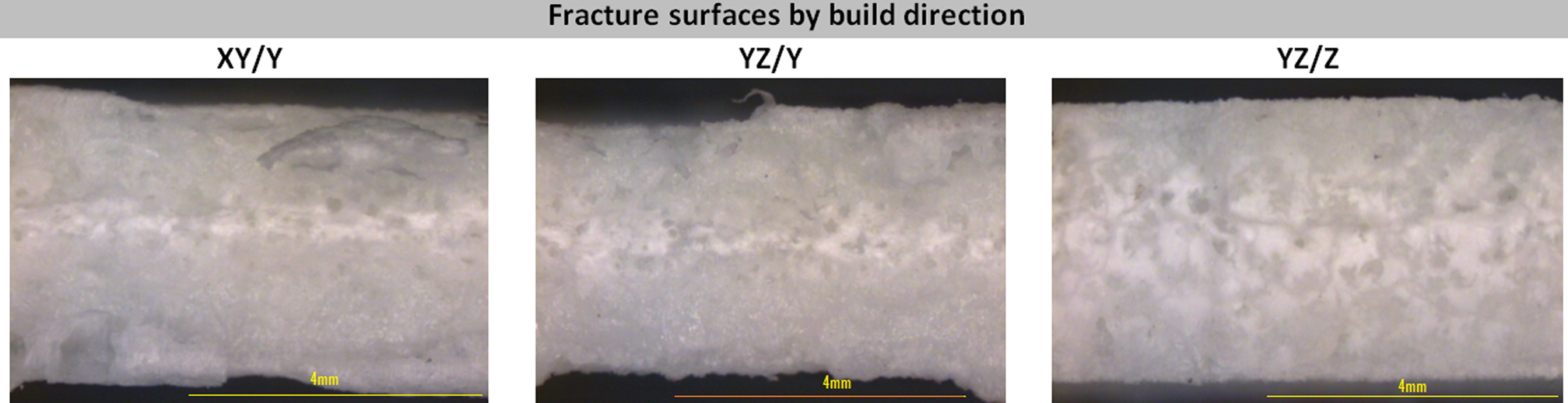
Fracture surfaces of reversed bending specimens
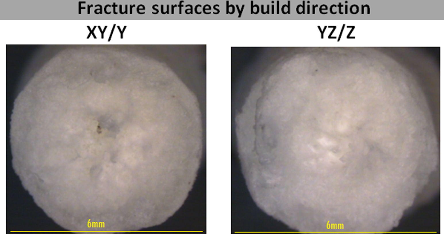
Fracture surfaces of rotating bending specimens
Discussion
Quality of test specimens
Materialise are experienced suppliers of SLS Nylon parts who used their standard commercial processing conditions to produce the parts used in the present study. In terms of the dimensional accuracy, density, surface properties and performance during tests, the parts proved to be within expected standards. However, clearly, it is important to demonstrate that the specimens were representative of those that can be expected from SLS of Nylon 12. In order to make this case, we would note the following:
all specimen dimensions were below 1% error when compared to nominal CAD dimensions all calculated densities were above 900 kg m− 3, which is considered a good benchmark for laser sintered parts;12,19 a slightly lower density was found on specimens built oriented along the Z direction as also noted by other researchers18,19 the tensile test results confirm all values fall within the expected levels quoted by the manufacturer for tensile strength, modulus and strain at break.
17
Overall, we consider these specimens to be representative of those provided by reputable suppliers of SLS Nylon 12, and in particular to exhibit the material behaviour commonly exhibited by laser sintered Nylon 12.
Isotropic fatigue behaviour
In both the rotational and reversed bending fatigue tests, the outcome was a set of S–N curves, which did not show any significant anisotropic response. When added to previous observations9–12 of seemingly, at least to a first order approximation, isotropic fatigue behaviour of laser sintered Nylon 12, this presents a fairly compelling case for the material being considered isotropic in terms of its fatigue properties, despite anisotropic failure properties from static load to failure tests, shown in this case in Fig. 8. Fatigue of polymers is commonly associated with localised heating and deformation, 20 and we would speculate that this localised heating and deformation acts to create a uniform microstructure at the eventual fracture site, through an in situ drawing and/or annealing process. It is worth noting that, although the reversed bend test mode encourages delamination, no gross delamination failures were observed. The initiation of surface cracks is considered to be the key life determining event in both test modes.
Equivalence of loading modes
The S–N curves in Fig. 11 for the reversed and rotational bending tests were not statistically different. This result suggests that the generally higher frequency (and therefore faster) rotational bending fatigue tests can be used to gain a good indication of the fatigue behaviour of laser sintered Nylon 12. The frequency used in the tests detailed in the present paper has been 30 Hz, but we have previously shown that fatigue test data at 30 and 50 Hz for a similar material is broadly equivalent. 12
Implications for fatigue testing of laser sintered Nylon 12
A key comment to make about the data presented in the present paper is that it applies to a set of test specimens all prepared on a single machine within a single build. A longitudinal study with a single material across several machines will be pursued as future work. However, fatigue testing is time consuming and expensive. Our qualified advice on the basis of the information we have available from the present study and others would be that testing fatigue properties of laser sintered Nylon using a rotational bending rig will give efficient and representative fatigue behaviour regardless of the orientation of the specimens.
Conclusions
For a set of Nylon SLS test samples prepared on a single SLS machine as part of a single build, our results showed that the fatigue behaviour was isotropic and that there was no statistical difference between rotating and reversed bending fatigue properties.