
Abstract
The evolution of microstructure and phase formation in equiatomic Ti20Fe20Ni20Co20Cu20 high entropy alloy synthesised by conventional arc melting followed with suction casting and ball milling with spark plasma sintering route is distinctly different. The cast microstructure exhibits one body centre cubic and two face centre cubic high entropy phases based on titanium, cobalt and copper respectively along with a eutectic containing Ti2Ni type Laves phase. On the contrary, spinodal decomposed microstructure consisting of cobalt and copper solid solution is obtained in the sintered sample. However, long term annealing of cast sample at 950°C reveals a eutectoid transformation with different phases than the cast sample. The aforementioned observations are discussed using CALPHAD thermodynamical approach and available literature.
Introduction
High entropy alloys (HEAs) with five or more elements in equiatomic compositions offer a new class of material with tunable properties like high strength, ductility and excellent wear resistance and high temperature stability.1,2 The field of HEA being ∼10 years old, processing–microstructure–properties paradigm is yet to be established for these alloys, and the sustained effort in measurement of complete physical and mechanical properties is essential to realise the complete potential of these alloys. It is to be noted that there is no single application of these alloys realised as yet. However, these alloys can be used for engineering applications only after establishing a correlation between microstructural evolution and the processing route. High entropy alloys are predominantly extended face (fcc) or body centred cubic (bcc) solid solutions with single or multiphase microstructures.3–5 The higher fraction of multiple alloying elements leads to the formation of extended solid solutions instead of formation of brittle intermetallic phases.1,6–8 High entropy alloys are formed due to significant contribution of entropy of mixing, mainly configurational entropy, which is maximised by the presence of different elements in equiatomic ratio and is >1.61R, where R is the universal gas constant. 9 It has been shown that the entropy contribution is always greater than the enthalpy contribution for HEAs. 4 In addition, HEAs are characterised by sluggish diffusion compared to binary alloys as well as severe lattice distortions and cocktail effects. 10 As mentioned earlier, the cocktail effect, wherein the properties of the multicomponent phase is completely different from the constituent components, renders unique properties to the HEAs. This aspect is one of the least understood in the HEA systems and needs further investigation. In addition, these alloys present a unique case to explore relative contribution of enthalpy and entropy to the overall Gibbs free energy that determines the stability of formation of a phase in multicomponent alloys.
High entropy alloys can be obtained in different forms ranging from bulk to thin film and cast ingots and slabs to powders. However, there exist two important processing routes to prepare HEAs in the bulk form. They include casting (vacuum arc melting cum suction casting) and mechanical alloying (MA) followed by sintering.1,3,11,12 The difference in the processing routes essentially affects the formation of the HEA phases and hence controls the evolution of the microstructure. The suction casting route involves the phase formation from the liquid state, whereas MA is a solid state process involving severe plastic deformation of the powder constituents. 13 Therefore, it is expected that phase formation and the microstructural evolution will strongly depend on the processing route for a particular HEA, and thus, it is worthwhile to study the effect of kinetics on the evolution of different phases and stability in a HEA. In addition, different processing routes can offer a variety of liquid to solid as well as solid state transformations to obtain HEA phases from the multicomponent constituents. Thus, the processing route is bound to affect the formation of HEA from the constituent components in a drastic way. In the present investigation, Ti20Cu20Fe20Co20Ni20 HEA has been chosen as a model system to study the effect of different processing routes on microstructural evolution and phase stability. This alloy has been synthesised by MA followed by spark plasma sintering (SPS) and conventional melting and suction casting solidification processing route. A detailed structural evolution of the alloy was carried out using X-ray diffraction (XRD), while microstructural investigation was carried out using scanning electron microscopy (SEM) and transmission electron microscopy (TEM). Thermodynamic modelling was carried out by commercially available software Thermo-Calc 3.0.1. using TCFE7 database to explain the stability of phases in different routes and explain the similarities and differences in the phase formation. 14 Although Thermo-Calc has no specific database for five component systems, it is possible to obtain reasonable results using available databases.15,16 Earlier works 16 suggest that it is reasonable to utilise the exiting databases to obtain results. High fidelity of the CALPHAD approach from the literature and our own experimental results indicate us to rely on the validity of the same.
Experimental
The multicomponent Ti–Cu–Fe–Co–Ni HEA ingots were synthesised by vacuum arc melting of pure elements Ti, Cu, Fe, Co and Ni ( ≥ 99.99 mass purity, Sigma-Aldrich, USA) on a water cooled copper hearth using non-consumable tungsten electrode under high purity argon atmosphere. This was followed by direct casting into cylinder rods (ΦΦ) 3 mm diameter and 50 mm length using in-house suction casting facility.
Elemental powders Ti, Fe, Co, Ni and Cu with high purity (>99.9 ) were used as starting materials for MA, which was carried out in Pulverisette-5 planetary ball mill (Fritsch, Germany) with tungsten carbide (WC) vials into which the powders were sealed together with WC balls in dry condition under the protective argon atmosphere. Powders were milled up to 15 h at the speed of 200 rev min− 1 with ball/powder weight ratio of 20:1. Before the milling, the WC vials containing powder and balls had been evacuated to 10− 3 torr and refilled with high purity (99.9) Ar gas. To retain the protective Ar atmosphere inside the vials, the milling operation had intermittently been stopped and high purity Ar gas had been refilled. The SPS of the as milled powders was carried out using a Dr. Sinter 515S apparatus (SPS Syntex Inc., Kanagawa, Japan) with a pulse on/off ratio of 12:2. The as milled powder was loaded in a 15 mm diameter graphite die and was placed inside the SPS chamber between two graphite electrodes under a vacuum level of 6 × 10− 3 torr. High purity (99.9) Ar gas was then purged with a flowrate of 2 L min− 1 in the chamber to ensure minimal oxidation of the powders. The powder was heated to 900°C with the heating rate of 100°C min− 1 and then held at the sintering temperature for 6 min before it was furnace cooled to room temperature, with a uniaxial pressure of 50 MPa throughout the sintering cycle. Using a K1 type chromel–alumel thermocouple, the temperature of the sample was monitored, which was inserted in the die at a distance of 0.002 m from the inner die wall so that the recorded temperature difference between the sample and die was minimum. During the SPS experiment, while a constant voltage of 20 V was applied, the current flow varied ∼900 A. The processed pellets and suction cast rods were subjected to metallographic sample preparation techniques to obtain a mirror polish. The density of all SPS processed samples was determined according to Archimedes’ principle using distilled water. The theoretical density for the sintered composition was calculated following the rule of mixtures, considering the theoretical densities of pure elements (ρTi = 4.51 g cc− 1, ρCu = 8.96 g cc− 1, ρNi = 8.9 g cc− 1, ρFe = 7.87 g cc− 1 and ρCo = 8.86 g cc− 1, where ρ stands for density). The phase identification of the specimen was carried out using X-ray diffractometer (PANalytical X'Pert PRO MRD) and Bruker Focus diffractometer with Ni filtered Cu Kα (λ = 0.154056 nm) and V filtered Cr Kα (λ = 0.228976 nm) radiation. The morphology, size and distribution of phases in the investigated alloys were characterised using SEM (Carl Zeiss 50 VP) operated at 20 kV. The local composition of the phases was determined using energy dispersive spectroscopy (EDS; INCA Penta Fet X3) coupled with SEM. The finer scale microstructure was analysed by TEM (UT20) operated at 200 kV. Samples for TEM observation were prepared by the standard preparation technique, which includes cutting of 3 mm discs, grinding, dimpling and subsequent ion milling using argon gas ions at 5 kV at an angle of 4° until perforation occurred. The phase evolution has been studied using Thermo-Calc 3.0.1 software using TCFE7 database.
Results
X-ray diffraction analysis
Figure 1a shows the XRD patterns of the suction cast cylinders of Ti20Cu20Fe20Ni20Cu20 alloy annealed at three different temperatures. The patterns of the as cast alloy cylinder before the heat treatment are also provided at the bottom of Fig. 1a. The XRD pattern of the as cast alloy cylinder shows the intense diffraction peaks corresponding to fcc (α1) phase (Fm3¯m; a = 0.3615 nm), fcc (α2) phase (Fm3¯m; a = 0.3544 nm), bcc (β) phase (Im3¯m; a = 0.3306 nm) and the Laves phase (Ti2 (Co, Ni) type, Fd3¯m; a = 1.129 nm). 12 The XRD patterns of the annealed sample at different temperatures show the presence of same diffraction peaks in all the alloys annealed up to 800°C. However, at 950°C, the peaks corresponding to a Ti2Cu (I4/mmm; a = 0.294 nm, c = 1.078 nm) with α-Ti (P63/mmc; a = 0.295 nm, c = 0.467 nm) appear in the pattern. The peaks of different phases remain broad even in the annealed samples.
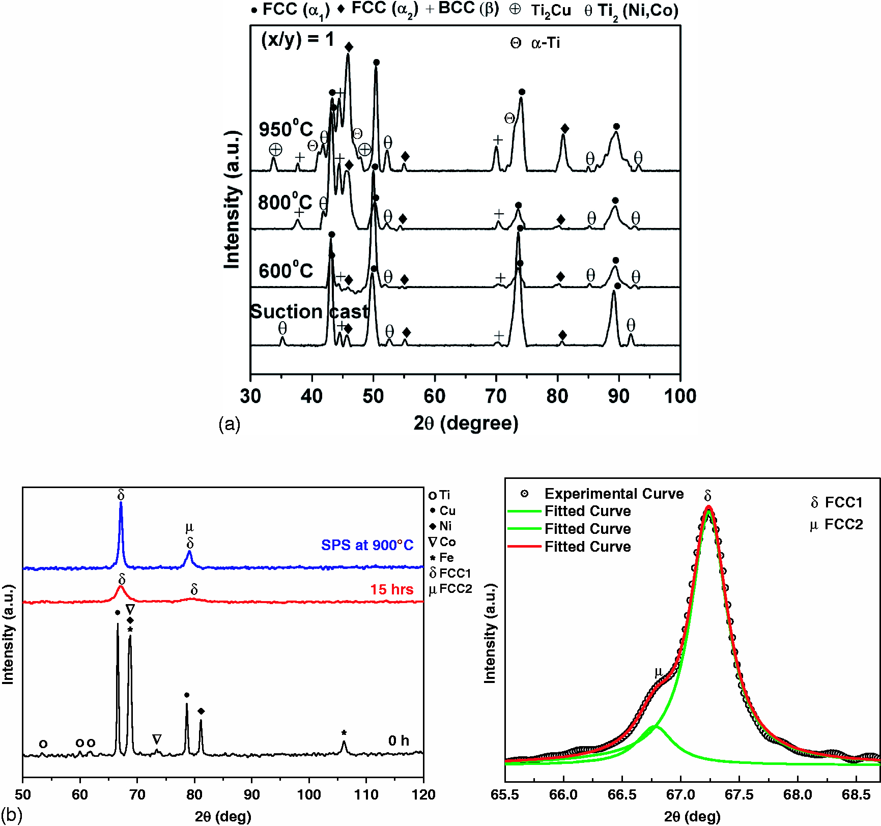
X-ray diffraction pattern of Ti20Cu20Fe20Ni20Cu20 HEA: a produced by melting cum suction casting and b mechanical alloying followed by spark plasma sintering at 900°C; bottom inset shows enlarged view of deconvoluted peaks of sintered sample
On the other hand, Fig. 1b shows the XRD patterns of Ti20Cu20Fe20Ni20Cu20 HEA powder before and after ball milling for 15 h. Predominant peaks of a single phase fcc solid solution (α) (a = 0.3596 nm) within the detectable limit of XRD is observed in the mechanically alloyed powder. The XRD pattern of the as mixed powder is also shown at the bottom of the figure. Therefore, the powder mechanically alloyed for 15 h have been used for subsequent consolidation. Furthermore, broadening of the peaks corresponds to the nanocrystalline nature of α grains. Figure 1b also shows the XRD pattern of the pellet after densification by SPS at 900°C. It indicates that the bulk alloy consolidated after SPS consists of the mainly δ (fcc1, a = 0.359 nm) phase and another minor new μ (fcc2, a = 0.362 nm) phase. The bottom inset shows the enlarged view of the deconvoluted peak, indicating the presence of δ and μ peaks. Hence, it can be postulated that single phase α supersaturated solid solution transforms to δ phase along with μ phases during sintering using SPS.
Scanning electron microscopy analysis
The SEM images of the solidified multicomponent Ti20Cu20Fe20Ni20Cu20 HEA after heat treatment at different temperatures are presented in Fig. 2. The backscattered electron (BSE) images and EDS of the solidified multicomponent Ti20Cu20Fe20Co20Ni20 HEA reveals the presence of different phases, namely, Ti rich solid solution (β) phase (black contrast), Cu rich solid solution (α1) phase with white contrast and Co rich solid solution (α2) phase with light grey contrast as well as dark grey Laves phase [Ti2 (Co, Ni) type]. The micrographs of sample annealed at 600°C (Fig. 2a) clearly reveal the presence of ultrafine eutectic between α1 phase and Ti2 (Co, Ni) type Laves phase along with dendrites of α2 phase and β phase. Moreover, Ti rich solid solution [bcc (β) solid solution] is also observed in the microstructure as freely growing dendrites indicating that it has been formed first from the liquid. Figure 2b and c shows the representative BSE SEM images of the annealed specimens at temperature of 800 and 950°C. The microstructure is observed to be stable up to 800°C. All the three phases (α1, α2 and β) are present, and shape and size of the β-dendrites and α1 droplets have not undergone substantial change during heat treatment till 800°C. However, some distinct changes in the microstructure occurred in the specimen annealed at 950°C (Fig. 2c). The α1 is observed to form small droplets well distributed in α2 phases. The β phase retains the dendritic morphology.
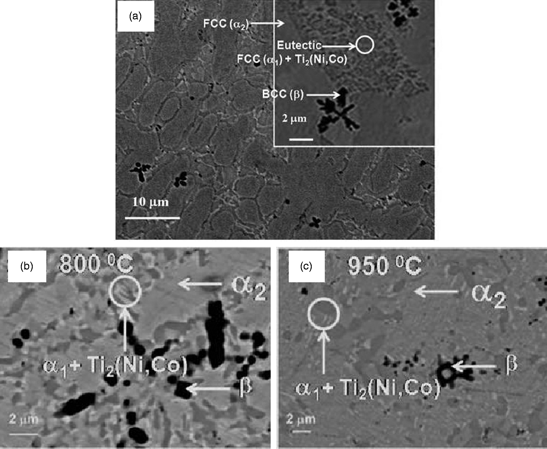
Images (SEM backscattered electron) of suction cast (Φ = 3 mm) multicomponent Ti20Cu20Fe20Co20Ni20 HEA annealed at a 600°C, b 800°C and c 950°C
Let us now discuss the SEM microstructures of the consolidated samples obtained by sintering at different temperatures. Figure 3a–c shows the BSE SEM images of the sintered samples. In general, the microstructures are observed to be consisting of two distinct phases with grey and black contrast. Spot EDS analysis indicates that black contrast phase is δ (fcc1), i.e. Co rich solid solution, whereas grey contrast phase is μ (fcc2) Cu rich solid solution. The relative distribution of δ and μ phases in the microstructure depends on the sintering temperature. In some of the areas (as indicated in Fig. 3c), one can even observe the presence of μ precipitates within the δ regions. Maximum relative density of 92.6 ± 0.5 to 95.4 ± 0.5 has been observed for the SPS processed sample in the aforementioned temperature range.
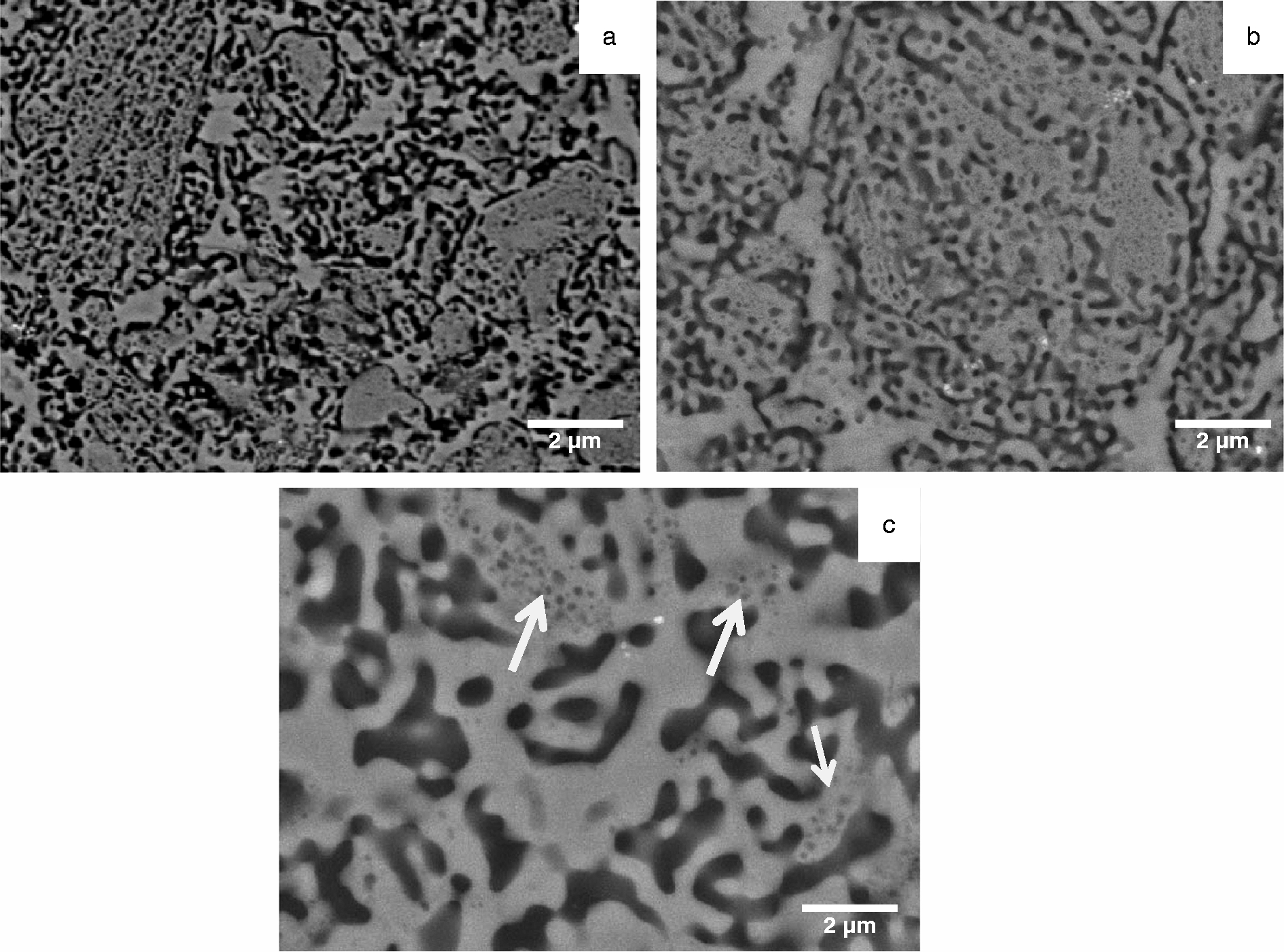
Images (SEM backscattered electron) of consolidated multicomponent Ti20Cu20Fe20Co20Ni20 HEA sintered at a 700°C, b 800°C and c 900°C
Transmission electron microscopy analysis
Solidified Ti20Cu20Fe20Ni20Cu20 HEA
Figure 4a displays the TEM images and the selected area diffraction (SAD) pattern from the constituent phases in the microstructure of as cast Ti20Cu20Fe20Ni20Cu20 HEA, synthesised by solidification route. The microstructure of the alloy consists of three solid solution phases: β, α1 and α2 along with eutectic between α1 and Ti2Ni type Laves phase. The indexed SAD pattern corresponding to each phase is shown as inset. The detailed analysis of the SAD patterns from α1 and α2 clearly indicate the presence of L12 and L10 ordering respectively. The SAD pattern corresponding to β phase reveals the presence of streaks and weak spots signifying incomplete displacive β → ω transformation, typically found in Ti based alloys. 17 The results of the TEM investigation on the solidified multicomponent Ti20Cu20Fe20Ni20Cu20 HEA, annealed at 950°C, are shown in Fig. 4b–e, revealing the presence of α1, α2, β along with eutectic between α1 and Ti2(Ni,Co). The morphology of α1 and Ti2Cu (alternate layers) indicates the eutectoid product of the following reaction (β → α-Ti + Ti2Cu). The detailed analysis of the SAD patterns from the phases specify that they have Ti2Cu and hexagonal close packed (α-Ti)ss phases respectively.
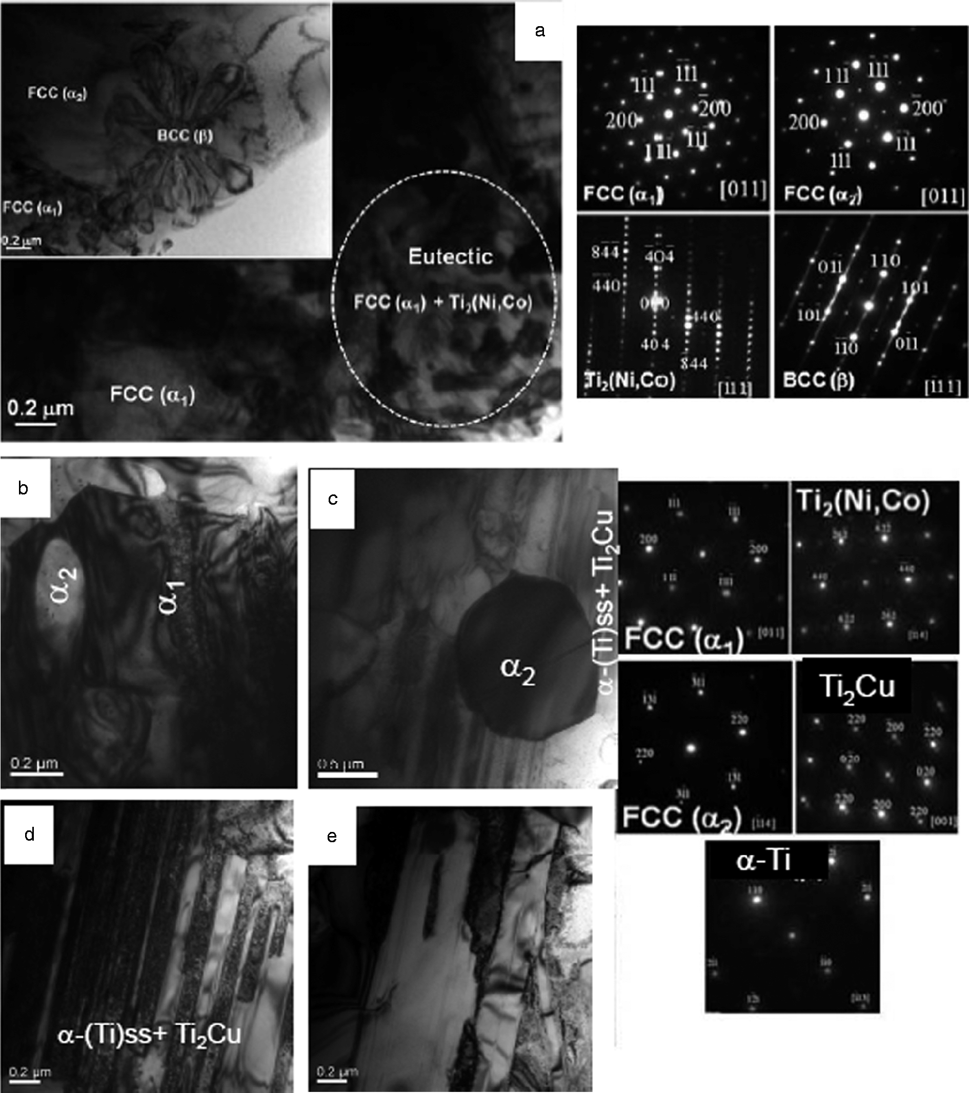
Images (TEM) of suction cast (Φ = 3 mm) multicomponent HEAs with corresponding SAD patterns from different phases as insets: a as cast microstructure showing different phases; b–e annealed at 950°C, revealing eutectics, dendritic phases and large number of eutectoid plates between α-(Ti)ss and Ti2Cu phases; e higher magnification BF image of eutectoid products; insets show SAD patterns of phases
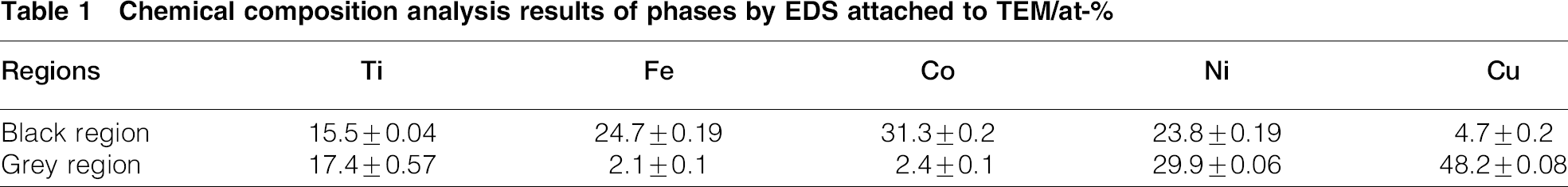
Figure 5 shows the salient results of the TEM investigation of Ti20Cu20Fe20Ni20Cu20 HEA consolidated using SPS. Figure 5a and b shows high angle annular dark field (HAADF) image of the sample sintered at 700 and 900°C. The HAADF images reveal the difference in contrast due to compositional variation or Z contrast. The worm-like microstructure observed is a typical feature of spinodal decomposition. One can observe the similarity in the SEM and TEM microstructure. These worm-like features are nearly oval in cross-section with a diameter of ∼200 nm. The periodicity, defined as the mean distance between two neighbouring structure varies from 50 to 70 nm. The detailed microstructural analysis using diffraction patterns and compositional analysis reveal that the Co rich phase imaged is dark, whereas Cu rich solid solution phase imaged is bright due to compositional contrast. The elemental compositional analysis carried out by energy dispersive X-ray spectroscopy (EDS) on all the phases is indicated in Table 1. Figure 5c is a higher magnification HAADF image of the compact prepared at 900°C, showing the details of the spinodal microstructure consisting of Co and Cu rich solid solution regions. The Co rich band-like structure is nearly oval in cross-section with 70 nm in diameter.
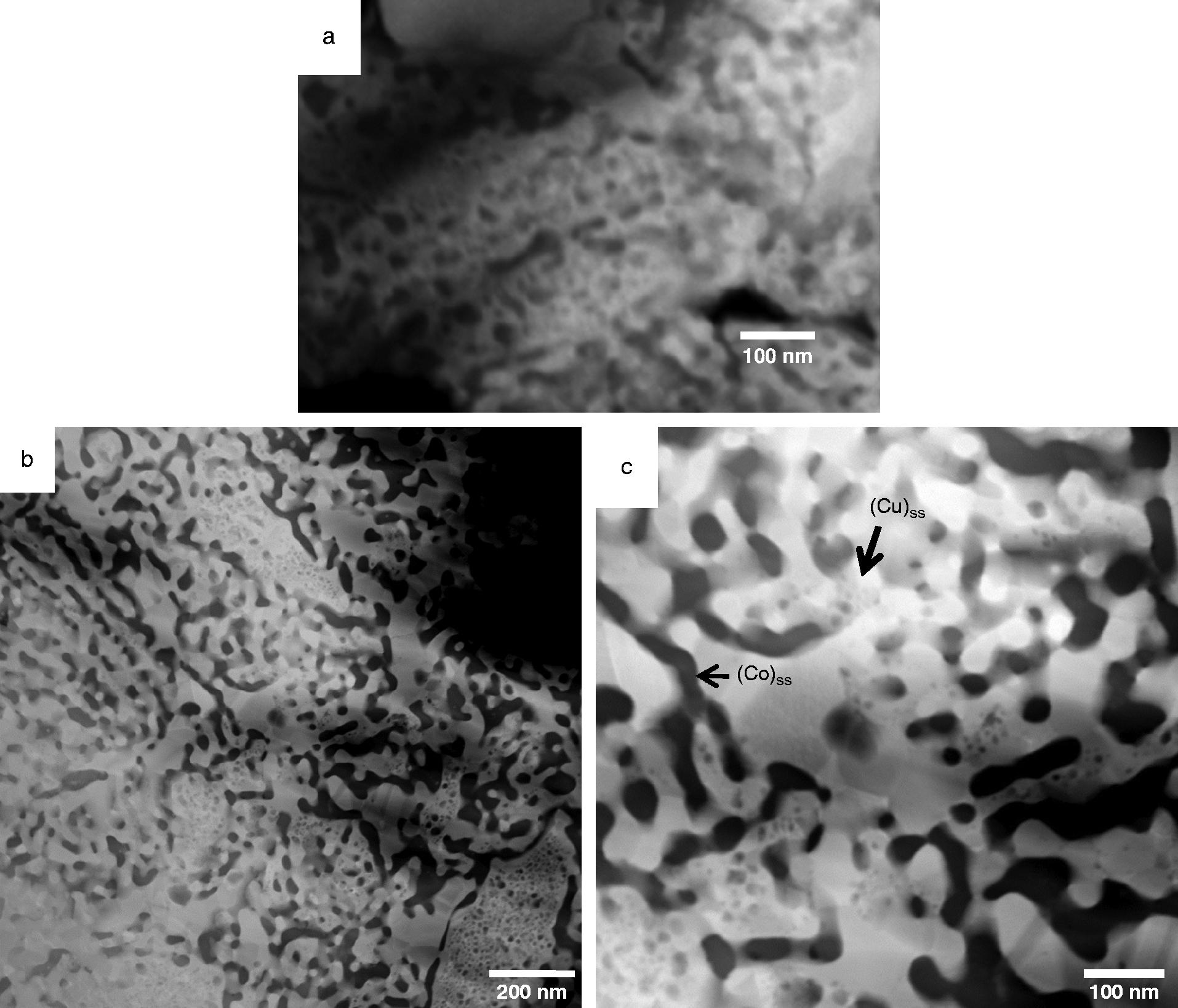
Images (HAADF) of consolidated multicomponent Ti20Cu20Fe20Co20Ni20 HEA sintered at a 700°C and b 900°C and c higher magnification HAADF image of pellet sintered at 900°C
Chemical composition analysis results of phases by EDS attached to TEM/at-
Discussion
The experimental investigations clearly indicate that there is a characteristic difference in phase evolution as a function of different processing route. The melting and casting route leads to the formation of a typical solidified microstructure comprising of dendrites of three solid solution phases with segregation in interdendritic region and a eutectic. However, non-equilibrium processing by SPS leads to a distinctly different microstructure showing spinodal decomposition. It would, therefore, be interesting to see the thermodynamic feasibility of the formation of phases. We shall now discuss the results taking into consideration the detailed microstructural investigation of the HEAs. The two important aspects would require explanations: phase formation of HEAs with corresponding microstructural evolution and thermal stability of the HEAs in Ti–Ni–Cu–Co–Fe system using existing literature as well as CALPHAD modelling.
Formation of HEA in Ti20Ni20Cu20Co20Fe20 alloy
It is indeed important to understand the phase formation as well as stability of novel HEAs because they exhibit lots of scientific challenge to the scientific community. The present experimental results conclusively suggest that it has been possible to form HEAs consisting of two fcc solid solutions and a bcc solid solution in the investigated alloys during solidification, whereas solid state processing of the alloy shows spinodal decomposition. In addition, Laves phase was not found in the sintered sample. It is to be mentioned here that Ni3Ti phase predicted by Thermo-Calc has not been found in any of the two differently processed samples. This is a unique finding in the sense that HEAs, being equiatomic multicomponent alloy systems, can offer possibilities of formation of different microstructures and thus properties.
We shall discuss this aspect from the thermodynamical approach. First, we shall elucidate the feasibility of formation HEAs in Ti–Cu–Fe–Co–Ni system using thermodynamical approach. Following Boltzmann's hypothesis, the configurational entropy change ΔSconf for formation of solid solution consisting of n elements is given by
8

According to earlier investigations,1,18 there are three key parameters responsible for the formation of stable HEAs: atomic size difference δ, enthalpy of mixing ΔHmix and configurational entropy ΔSconf of mixing. It has been explained that the formation of stable solid solution phases in the multicomponent HEAs is based upon the following criteria: 1 ≤ δ ≤ 6.6; − 15 ≤ ΔHmix ≤ 5 kJ mol− 1; and ΔSconf ≥ 1.61R, where R is the universal gas constant.1 Furthermore, the last two thermodynamics parameters can be coupled into one important parameter
18
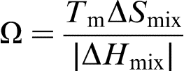
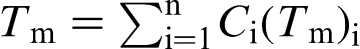
Thus, HEA phase will form when Ω ≥ 1.1 and δ ≤ 6.6. The calculated values of Ω and δ for the present HEA are listed in Table 2. It can clearly be observed that the formation of the stable extended solid solution phases is feasible for the alloy composition due to higher contribution from entropy. Similar results have been shown in earlier investigations by the authors.4,12 In addition, Guo et al.19,20 have reported that the design of the multicomponent HEAs to form the stable solid solution phases can also be rationalised by statistically analysing other two key parameters, electronegativity difference Δχ (Ref. 20) and valence electron concentration (VEC).
21
However, detailed study indicates Δχ does not have strong effect on the formation of the solid solution phases, whereas VEC can be used to quantitatively predict the phase stability of fcc and/or bcc phases in HEAs as per following conditions
if VEC ≥ 8.0, only fcc phases exist at 6.87 ≤ VEC < 8.0, mixed fcc and bcc phase will coexist if VEC < 6.87, bcc phase will exist.
Thermodynamic parameters such as δ, ΔHmix, ΔSmix, Tm, ΔG, Ω, VEC and Δχ calculated for alloy system under study
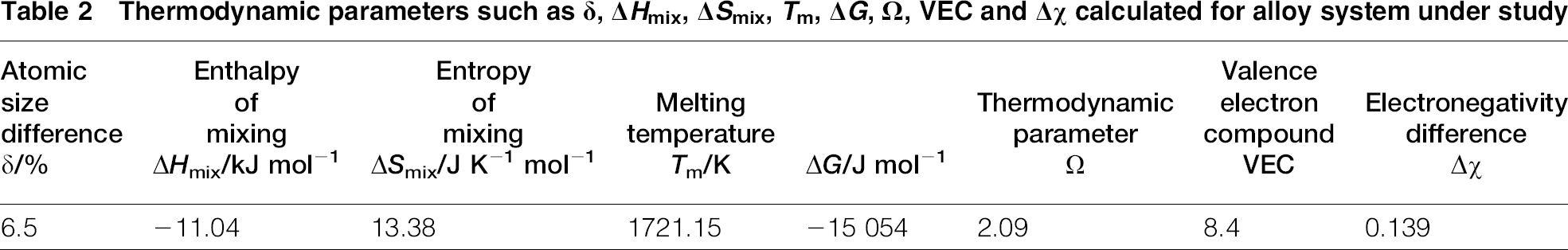
The calculated values of VEC for all the investigated alloys are also reported in Table 2. In the present investigation, VEC ≥ 8.0 for the alloy composition, and thus, fcc solid solution phase will exist. Experimentally, it has been observed that the majority volume fraction of phases in the microstructure is fcc phases (α1 and α2) with small quantity of bcc phase (β) and Laves phase. Thus, one can explain the stability of different phases in the HEAs using thermodynamical approach. However, such an approach does not allow finding out the possible phases formed and their relative stability.
Thermal stability of HEAs in Ti–Ni–Cu–Co–Fe
It is to be mentioned here that phase equilibria in a multicomponent system is determined by the total Gibbs free energy of the phases with the phase/s having the lowest Gibbs free energy being the stable one/s in a multicomponent system. One can use the CALPHAD (Computer Coupling of Phase Diagram and Thermochemistry) for detailed analysis of evolution of possible phases in a particular alloy. The CALPHAD formulation is based on calculation of free energy of a phase based on contribution of pure component, ideal mixing and excess free energy of mixing and is given for a phase p,  the second term corresponds to entropy of mixing of ideal solutions and is given by
  . The third term is the excess free energy of mixing for a regular solution and is given by
  .14–16 This term indicates the interaction of different components in a random solution, and L
ijp
model parameters need to be determined using statistical techniques to obtain best fit to the available experimental data for a given combination of component and phases. Thermodynamic data for the five elements and their binary constituents are available in the CALPHAD database, and necessary calculations providing free energy, enthalpy of mixing and entropy of different phases were obtained using Thermo-Calc. The Gibbs free energy values obtained as a function of temperature can be utilised to estimate the relative stability of different phases formed from the liquid state at different temperatures during cooling. Figure 6a shows the variation of Gibbs free energy of the phases as a function of temperature. At room temperature, the Gibbs free energy diagram predicts the presence of Cu and Co rich as well as Ti rich solid solutions and Ti2Ni Laves phases. This is in consonance with the observed microstructure in the suction cast alloys. This diagram also allows us to discuss the microstructural evolution. It is clear that, upon cooling, fcc2 (Co)ss phase is likely to form first followed by (Cu)ss. This can happen due to liquid phase immiscibility of these two phases. Since the enthalpy of mixing ΔHmix of Cu with Fe, Co and Ni is positive (i.e. ΔHCu–Fe = 13, ΔHCu–Co = 6 and ΔHCu–Ni = 4 kJ mol− 1), this leads to demixing of Cu with other elements. The liquid phase separation occurs by segregation of fcc (α1) at the interdendritic region leading to the formation of ultrafine eutectic phase mixture between fcc (α1) and Ti2(Ni,Co) type Laves phase. The bcc β-(Ti)ss phase forms at lower temperature ( < 800 K). In addition, Ni3Ti and a Laves phase are also expected to be stable in this temperature range for the Ti20Cu20Fe20Ni20Cu20 HEA. However, the presence of Ni3Ti is not observed in the microstructure. This may be due to kinetic constrains. Therefore, it is possible to explain the phase formation and the microstructural evolution by CALPHAD modelling.
.14–16 This term indicates the interaction of different components in a random solution, and L
ijp
model parameters need to be determined using statistical techniques to obtain best fit to the available experimental data for a given combination of component and phases. Thermodynamic data for the five elements and their binary constituents are available in the CALPHAD database, and necessary calculations providing free energy, enthalpy of mixing and entropy of different phases were obtained using Thermo-Calc. The Gibbs free energy values obtained as a function of temperature can be utilised to estimate the relative stability of different phases formed from the liquid state at different temperatures during cooling. Figure 6a shows the variation of Gibbs free energy of the phases as a function of temperature. At room temperature, the Gibbs free energy diagram predicts the presence of Cu and Co rich as well as Ti rich solid solutions and Ti2Ni Laves phases. This is in consonance with the observed microstructure in the suction cast alloys. This diagram also allows us to discuss the microstructural evolution. It is clear that, upon cooling, fcc2 (Co)ss phase is likely to form first followed by (Cu)ss. This can happen due to liquid phase immiscibility of these two phases. Since the enthalpy of mixing ΔHmix of Cu with Fe, Co and Ni is positive (i.e. ΔHCu–Fe = 13, ΔHCu–Co = 6 and ΔHCu–Ni = 4 kJ mol− 1), this leads to demixing of Cu with other elements. The liquid phase separation occurs by segregation of fcc (α1) at the interdendritic region leading to the formation of ultrafine eutectic phase mixture between fcc (α1) and Ti2(Ni,Co) type Laves phase. The bcc β-(Ti)ss phase forms at lower temperature ( < 800 K). In addition, Ni3Ti and a Laves phase are also expected to be stable in this temperature range for the Ti20Cu20Fe20Ni20Cu20 HEA. However, the presence of Ni3Ti is not observed in the microstructure. This may be due to kinetic constrains. Therefore, it is possible to explain the phase formation and the microstructural evolution by CALPHAD modelling.
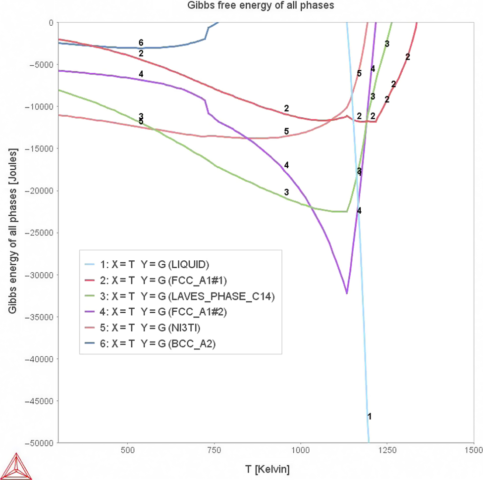
Variation of Gibbs free energy of phases as function of temperature for Ti20Cu20Fe20Co20Ni20 HEAs
Let us now discuss the phase and microstructural evolution in the sintered specimens prepared using mechanically alloyed powder. Earlier works on Cu–Co system using rapid solidification 22 as well as MA 23 indicate that it is possible to form a homogeneous solid solution of Cu and Co when particle size is reduced to nanoscale depending on the alloy composition and temperature.
It is to be mentioned here that it is not possible to incorporate the effect of processing route in these calculations per se, but the observed differences can be explained on the basis of phase diagrams for non-equilibrium conditions available in the literature and the sintered alloy. However, detailed microstructural and structural investigations indicate that the Laves phase formed during solidification is not found during SPS.
For alloys with negative heat of mixing, the phase formation during MA can be explained due to interdiffusion of the components. For multicomponent alloys, the formation of intermetallic compounds are suppressed or energetically destabilised due to chemical disorder created by the process of MA, resulting in the formation of extended metastable solid solutions or amorphous phase. For the alloy system with positive heat of mixing, such as Cu–Ti–Ni–Co–Fe, the diffusional reaction may result in the decomposition of the alloy. The formation of single phase explained solid solution in the present alloy system during MA can be explained due to following factors:
High defect density (dislocations, twins, etc.) during initial stages at MA of individual powder
24
Deformation of the component or fragments leads to formation of small tip radius so that capillary effects cause alloying
25
Energy stored at large number of grain boundaries of the nanocrystalline powders provides extra driving force for formation of metastable solid solution
26
The reduction of crystallite size leads to excess enthalpy due to additional Cu/Co interfaces;
23
these interfaces can cause the excess chemical enthalpy originating from the interface unlike neighbours.
CALPHAD calculation by Hasebe and Nishizawa
27
has shown that it is possible to calculate the excess chemical enthalpy of coherent Cu/Co interface, which is ∼4 kJ g− 1 atm− 1 when the particle size is 2 nm. This can lead to formation of extended solid solution. The formation of extended solid solution can be conceived akin to order–disorder transformation, where enthalpy is increased due to disordering. The driving force comes from enthalpy of mixing of the disordered alloys, which is much higher than the entropy of the phase separated composite. The entropy of mixing for a HEA phase is even much higher due to the presence of multiprinciple elements. In addition, the presence of other alloying elements, such as Ti, Ni and Fe, can make the formation of extended solid solution easier by changing the interactive potential of Cu and Co. Thus, the formation of metastable Cu–Co solid solution can be explained.
This solid solution is metastable and is energetically stabilised due to defects and interfaces. Therefore, upon heating to high temperature (600, 700 for 900 or 1000°C) during SPS, the metastable solid solution decomposes to (Cu) and (Co) rich solid solution. It is to be noted that the present alloy system can be considered as extension of Cu–Co system, which will predominantly partition while Ti and Ni will partition with both. Thus, observed spinodally decomposed microstructure can be explained using the metastability miscibility gap present in the Cu–Co system.22,28 Therefore, the heating of the mechanically alloyed powder to higher temperature destabilises the extended solid solution α, which therein decomposes by spinodal decomposition into two solid solutions, (Cu) and (Co) rich. The detailed investigation on the phase separation is under study and will be communicated later.
Conclusions
The present investigation conclusively shows that it is possible to tailor the microstructure of a bulk HEA by changing different processing routes. The following conclusions can be drawn from the investigation.
During solidification of equiatomic Ti20Ni20Cu20Co20Fe20, three HEA phases, body centred cubic titanium solid solution dendritic phases, face centred cubic copper and cobalt solid solution phase along with eutectic between copper solid solution and Ti2Ni Laves phase have been observed. On the other hand, MA of the Ti20Ni20Cu20Co20Fe20 alloy leads to the formation of single phase supersaturated face centred cubic solid solution, which during subsequent consolidation during SPS undergoes spinodal decomposition leading to the formation of copper and cobalt rich regions in the microstructures. The as cast microstructure is found to be stable during subsequent heat treatment. Specifically, all the phases except body centred cubic titanium solid solution phase remains stable till 950°C. The microstructural evolution in terms of phase formation can be explained using thermodynamical approach.
Acknowledgements
The authors would like to thank the Department of Science and Technology (DST), Indian Space Research Organization (ISRO) and Indian National Science Academy (INSA) for funding.