
Abstract
Large scale 30Cr2Ni4MoV ingots play a crucial role in nuclear power plants. Shrinkage and carbon segregation are the most common defects in the manufacture of these large scale ingots. Large scale ingots have very low cooling rates. In the present work, an experimental method was employed to achieve similarly low cooling rates with the aim of simulating the solidification process of large ingots in smaller 30Cr2Ni4MoV ingots.Thus, we examined the effect of surface pulsed magneto-oscillation (SPMO)on solidification structure in a laboratory setting. Our experimental results showed an SPMO treated ingot with less carbon segregation and a smaller shrinkage cavity than in an untreated one. Finally, the action mechanism was analysed by numerical simulation.
Keywords
magnetic flux density vector, Wb m− 2
solute concentration, g L− 1
specific heat, J kg− 1 K− 1
diffusion coefficient, m2 s− 1
electromagnetic force, N
magnetic field intensity vector, A m− 1
total current density vector, A m− 2
pressure, Pa
the amount of solute, g
time, s
temperature, °C
orthogonal velocity, m s− 1
global Cartesian coordinates, m
thermal conductivity, W m− 1 K− 1
Introduction
Large scale ingots have been widely used in aerospace, shipbuilding, electric power and other industries, but so far,consistent high quality and durability have remained out of the reach of manufacturers of these ingots. Shrinkage cavity and carbon segregation, which are their main defects, are difficult to eliminate by thermomechanical treatments.1–4 Li et al. developed a technique called ‘multiple pour’ to solve the problem of segregation and shrinkage in large ingots. 5 However, the pouring process is difficult to control. Campbell put forward that chemical segregation within the melt can be eliminated if the effective viscosity of the liquid metal can be artificially raised to such a degree that weak forces of convection are suppressed. He recognised, however, that this condition is difficult to achieve in industrial production. 6 Electric current pulse 7 and pulse magneto-oscillation (PMO), 8 both of which can change the liquid flow, can be used to significantly improve the solidification structure of metals and alloys. These processes have been attracting more and more attention because they are relatively green technologies. One disadvantage of electric current pulse, however, is that the electrode must be inserted into the melt. With high current, the melt might splash, making the process unsafe. 9 Pulse magneto-oscillation has been used in continuous casting in industry, but it is inappropriate for the production of large ingots. Surface PMO (SPMO) is a newly developed technology based on PMO that can be safely used in mould casting of large ingots. 10 In this process, a flat ring coil is inserted into the hot top after the melt has been poured; it does not contact the melt itself. Because the induction coil is placed on top of melt, the material of the mould does not interfere with the electromagnetic field. In addition, compared with other technologies, this process requires less slag to protect the melt from heat loss; the Joule heat generated by the electromagnetic field of the coil compensates for dissipated heat.
So far, however, SPMO is not well enough understood to be used successfully in the production of large ingots. In order to study the mechanisms involved in the production of a defect free large ingot, we designed a heavily insulated mould that would permit us to slow down the cooling rate of a small ingot (37 kg) to equal that of a large one.
Experimental
Our study material was 30Cr2Ni4MoV, which is mainly used in nuclear power rotors [chemical composition (wt-): 0.25C–0.05Si–0.3Mn–0.005P–0.005S–1.8Cr–0.4Mo–3.7Ni–0.01Al–0.1Cu–0.01Sn–0.001Sb–0.01As–0.1V]. The raw material (40 kg) was melted in a medium frequency induction furnace (9500 Hz frequency and 750 V output voltage), then heated up to 1560°C. Calcium, silicon and aluminium were chosen to deoxygenate the melt, which was subsequently poured into a mould with a diameter of 120 mm, height of 450 mm and wall thickness of 40 mm, preheated to 400°C (see Fig. 1 for a sketch of the experimental apparatus and the mould).
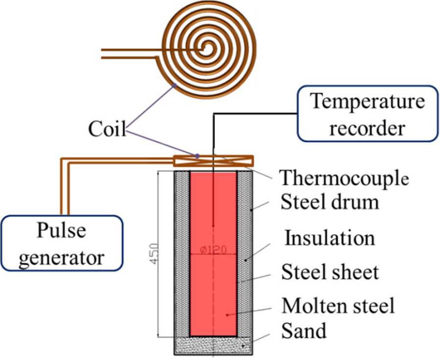
Schematic of SPMO casting set-up
In order to achieve a low cooling rate similar to that of large scale ingots, we formed a special mould by combining three parts fly ash (an excellent heat insulator) with one part sand, then moistening this mixture with liquid sodium silicate. We tamped this material down between the walls of two steel drums, the outside one having a wall thickness of 6.5 mm and the inside one of 0.7 mm. The major role of the two steel drums was to provide rigidity to the mould walls. This procedure was repeated for a second mould so that we would be able to test two ingots, one treated with SPMO and the other without.
After the melt was poured into the moulds, straw ash and ceramic fibre felt were placed on top of the melt surface to reduce heat loss. Then, in the mould, slated for SPMO treatment, a coil was placed on top of the felt. A W–Re thermocouple was inserted in the upper part of the melt to measure temperature. The curve of temperature and cooling rate is shown in Fig. 2. Li et al. measured and simulated the temperature distribution of 53 t ingot solidification process, in which the cooling rate was about 0.001–0.05 K s− 1. 11 The range of cooling rate in this experiment was about 0.01–0.22 K s− 1, which is near the cooling rate of a large one.
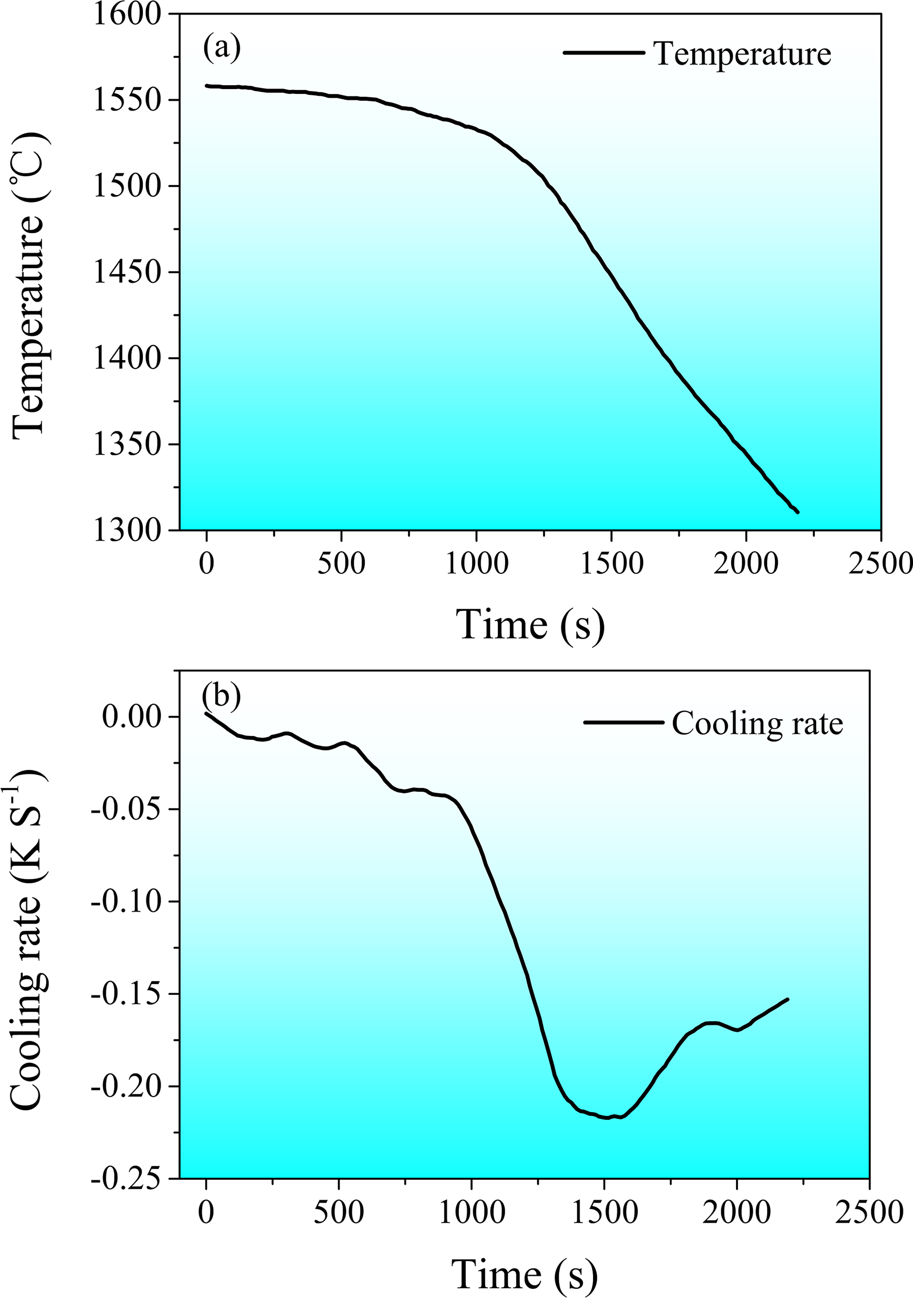
a temperature variation curve versus time; b cooling rate variation curve versus timeCooling curve of melt without SPMO treatment
Once the ingots had been cooled to room temperature, they were cut along the central plane to observe the macrostructure in the longitude section. Three specimensin the lower part (as shown in Fig. 3) were polished and etched with a solution of 50HCl and 50H2O at 70°C for ∼50 min. Chemical composition analysis was carried out using a direct reading spectrometer (PMI-MASTER PRO) with accuracy of 0.05.
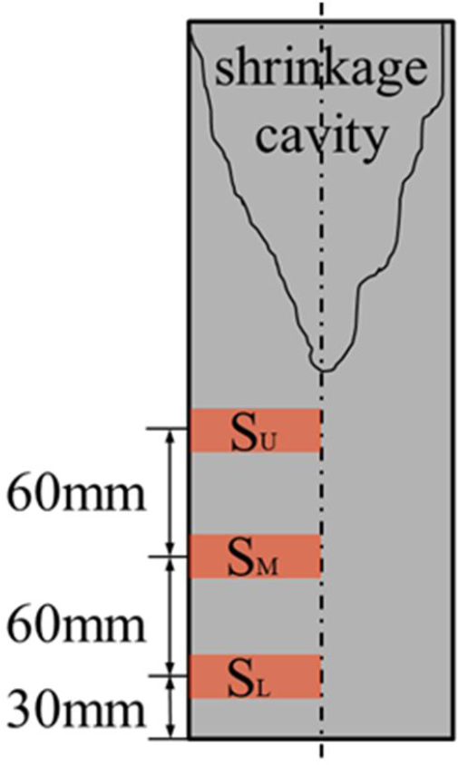
Sampling location: SL is 30 mm from bottom, SM is 90 mm from bottom and SU is 150 mm from bottom
Results
Shrinkage cavity
The size and distribution of the shrinkage cavity are important to the ingot. Figure 4 shows the treated and untreated ingots. Surface PMO reduced the depth of shrinkage cavity from 250 to 180 mm. Porosity is also obviously reduced in the SPMO treatment ingot, which can be found in SU specimen in Fig. 5.
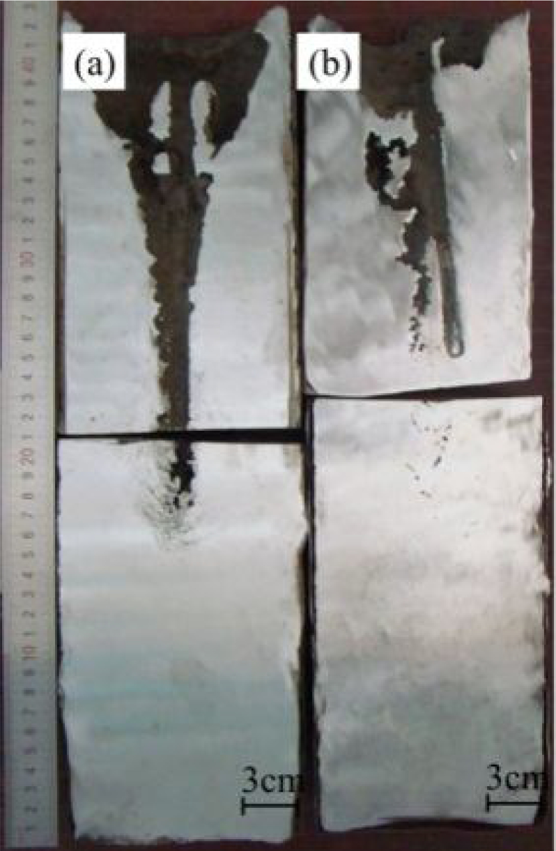
Overall pictures of ingots; a untreated, b treated
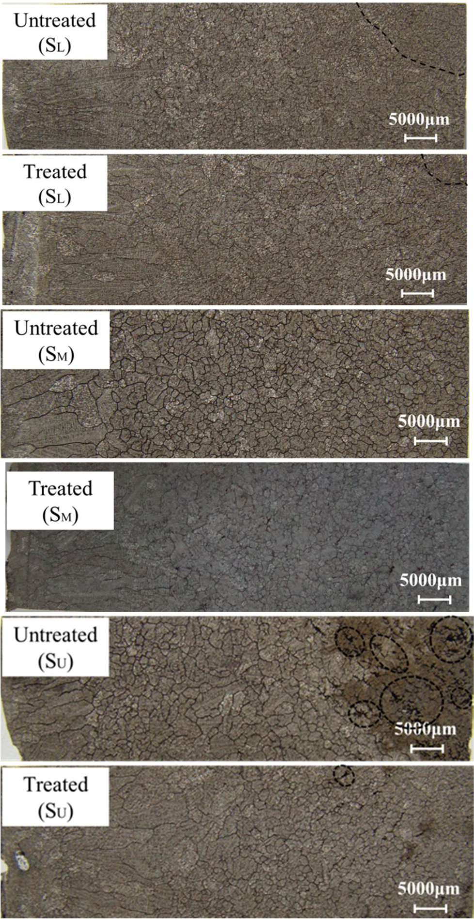
Solidification structure of untreated ingot and treated one: untreated (SL) and treated (SL) were 30 mm from bottom, untreated (SM) and treated (SM) were 90 mm from bottom and untreated (SU) and treated (SU) were 150 mm from bottom
Structures
Figure 5 shows the solidification structures of the lower parts of treated and untreated 30Cr2Ni4MoV ingots. For comparison, three specimens, labelled SL, SM and SU, were cut from the lower, middle and upper levels respectively, 30, 90 and 150 mm from the bottom. Because of the effectiveness of the insulation and the high preheated temperature of the mould, the cooler outer zone (the ‘chilled zone’) is very thin. The grains in both ingots are mainly columnar grains and central equiaxial grains. Because of the findings in our previous studies,10,12 we expected that SPMO treatment would refine both columnar and equiaxial grains, but we found instead that some of the equiaxial grains in the treated SL specimen were actually coarser than those in the untreated SL specimen, and SPMO decreases the area of fine equiaxial grains at the centre from 75 to 13.5 mm2.
In the SM specimen, the sizes of equiaxial grains are almost equal in the treated and untreated ingots. In the SU specimen, SPMO treatment made the equiaxial grains at the centre more uniform and fine, but large grains appeared near the columnar grain regions.
Solute distribution
Carbon segregation is a serious and persistent problem in the manufacture of large ingots. In the present study, we simulated in a laboratory sample (37 kg) with the heat transfer that would occur within a large ingot.Our aim was to determine whether SPMO would reduce carbon segregation under those conditions.
Carbon distribution was measured in the lower part of treated and untreated ingots. The distribution map of carbon segregation (i.e. ratio of the measuredvalue to the average value) in the two ingots is displayed in longitudinal section in Fig. 6. Serious carbon segregation appeared in the untreated ingot, creating an obvious negative carbon segregation zone at the bottom of the untreated ingot, a phenomenon that is common in the industrial production of large ingots.13,14 In the treated ingot, on the other hand,carbon segregation was significantly diminished.
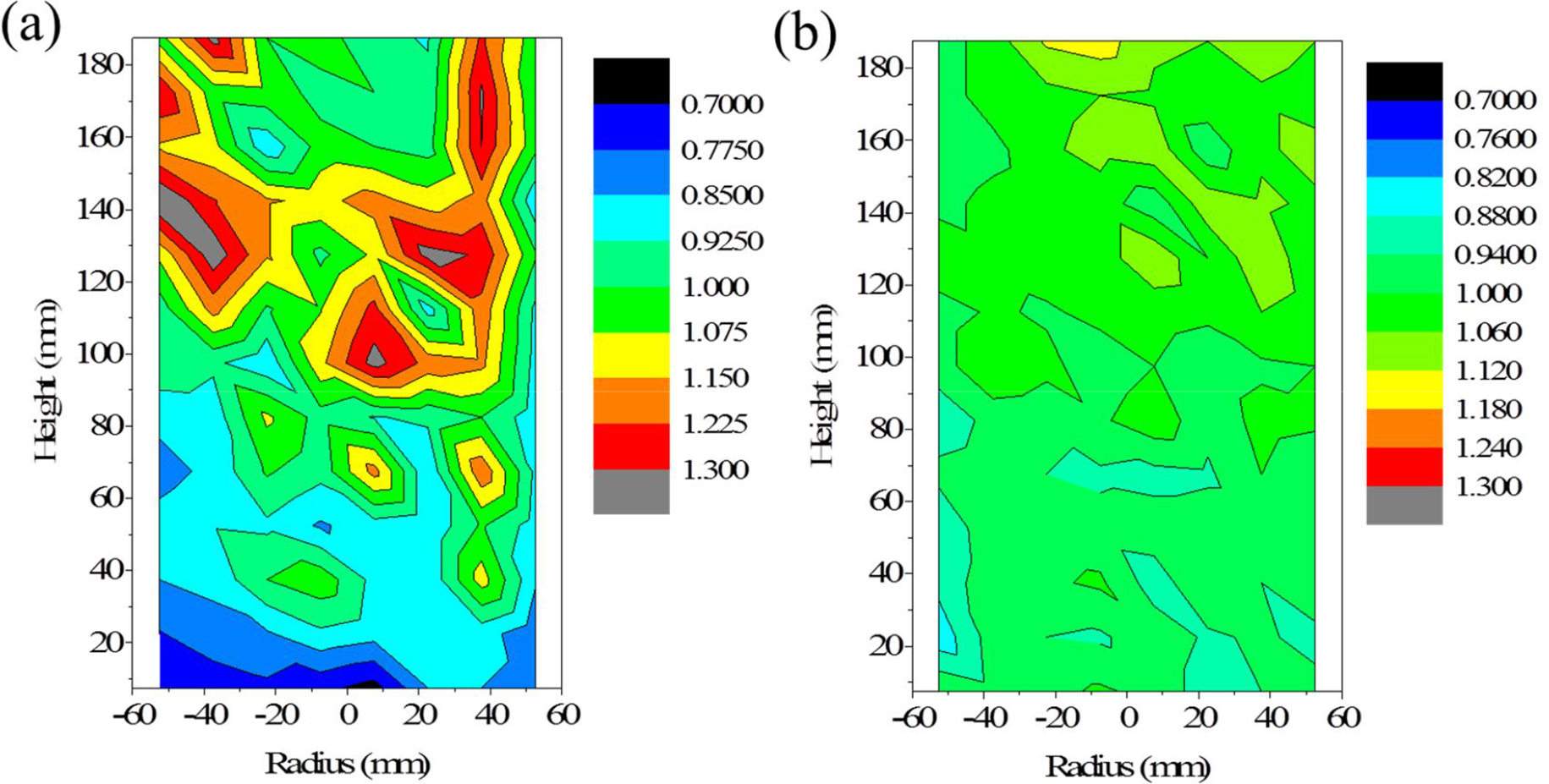
Carbon segregation distribution map in ingots; a untreated, b treated
More detailed comparisons were performed in axial and radial directions. Locations are shown in Figs. 7 and 8. Figure7 shows that axial distribution of carbon segregation in the treated ingot remained close to 1 (0.92–1.09), in a narrower range than that of the untreated ingot (0.7–1.25). Figure 8 shows radial distribution of carbon segregation at 30, 90 and 150 mm from the bottom. Radial carbon segregation in the treated ingot was significantly less than that in the untreated one at every level. Serious negative carbon segregation at the bottom of the ingot was eliminated by SPMO treatment.
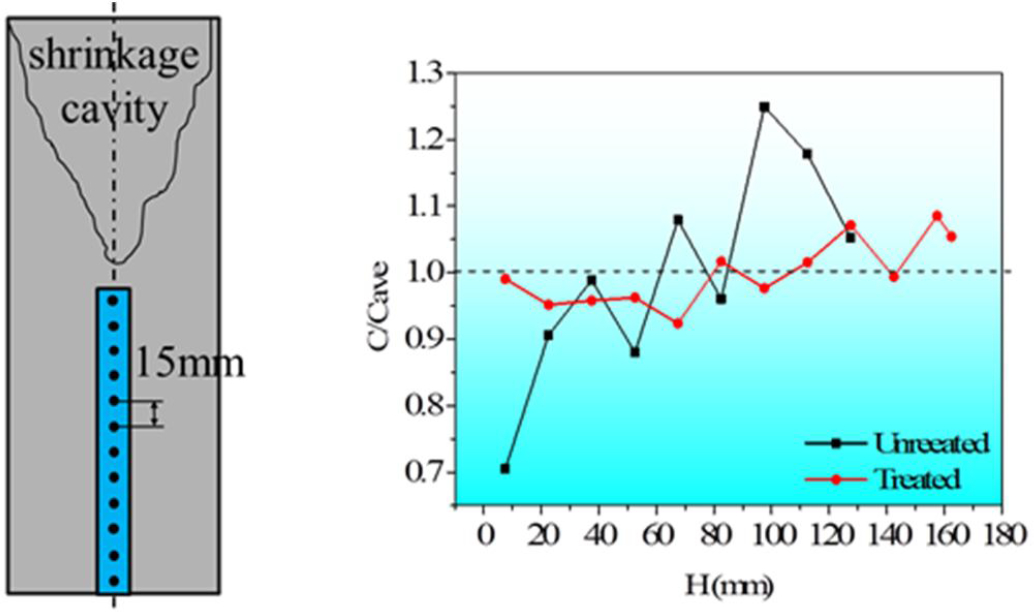
Axial distribution of carbon segregation
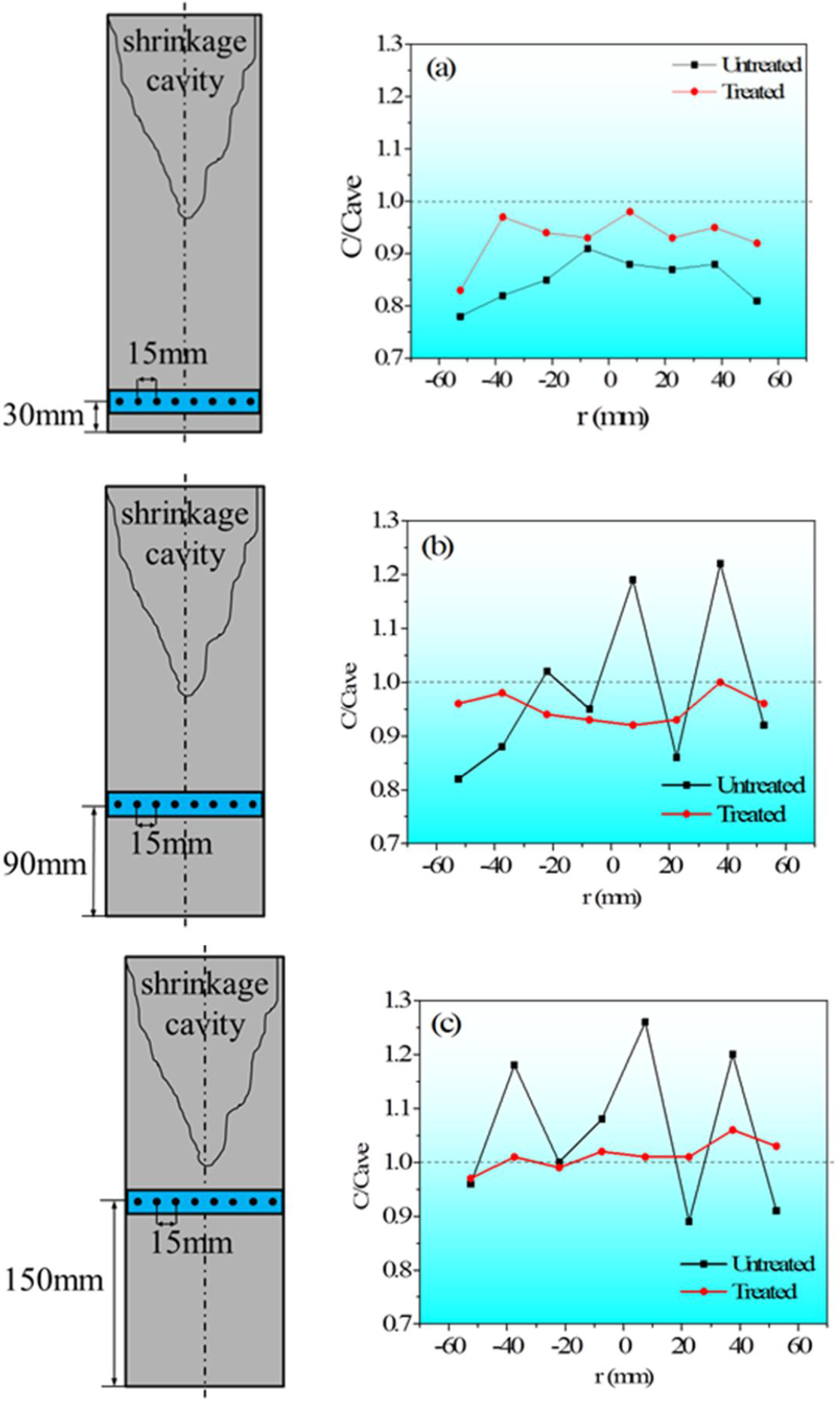
Radial distribution of carbon segregation: a 30 mm from bottom; b 90 mm from bottom; c 150 mm from bottom
Discussions
Electromagnetic force induced by the current in the coil can affect the flow in the melt 15 and, consequently, the movement of nuclei, heat transfer and solute transfer. Although the flow in a high temperature melt is practically impossible to measure directly, it can be calculated using numerical models. In the present study, we combined various models to simulate and analyse the mechanism that would be involved if large scale ingots were treated with SPMO.
Analysis of flow field in melt treated with SPMO
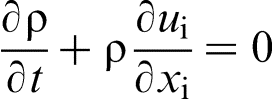
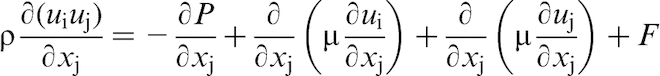
The convection of liquid metal can be described by the continuity equation (1) and the Navier–Stokes equation (2) as follows
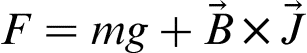
Without SPMO, melt convection is mainly caused by density difference, that is to say,  in equation (3). With SPMO, both electromagnetic force and gravity give rise to convection in the melt. Electromagnetic force and flow field in the SPMO treated melt were simulated using ANSYS (a commercial FEM software).
16
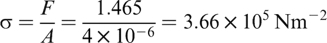
Electromagnetic force distribution is shown in Fig. 9. The largest electromagnetic force appears near the top surface and near the wall, with a maximum value up to 1.465 N. The force per unit area canbe calculated by
in equation (3). With SPMO, both electromagnetic force and gravity give rise to convection in the melt. Electromagnetic force and flow field in the SPMO treated melt were simulated using ANSYS (a commercial FEM software).
16
Electromagnetic force distribution is shown in Fig. 9. The largest electromagnetic force appears near the top surface and near the wall, with a maximum value up to 1.465 N. The force per unit area canbe calculated by
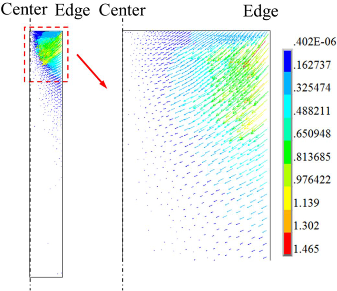
Electromagnetic force distribution in melt with SPMO
The gravity force per unit area was 6.9 × 10⁴ N m− 2 (ρT = 1600°C = 6.9 × 10³ kg m− 3), which is only approximately one fifth of the electromagnetic force. Electromagnetic force plays a dominant role in convection in an SPMO treated melt. 17 When electromagnetic force is treated as the driving force for melt convection in an SPMO treated melt, the flow pattern can be calculated by ANSYS (see Fig. 10). Electromagnetic force mainly affects the upper part of the melt, generating two vortexes in the part near the top wall.
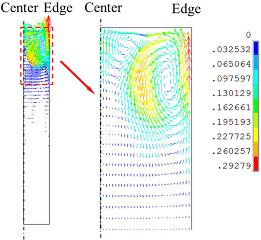
Flow field in melt with SPMO
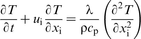
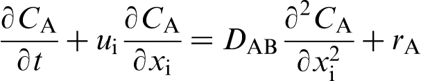
Taking convection into consideration, the heat and solute transfer processes can be expressed as equations (5) (heat) and (6) (solute). If convection is not considered, ui = 0 in equations (5) and (6). In other words, heat conduction and solute diffusion alone are weak and slow compared to convection transfer
Nuclei movement with SPMO
Nucleation begins at the surface and near the mould wall because of the higher cooling rates of these regions regardless whether SPMO is used. Without SPMO, gravity alone with weak natural convection makes the nuclei sink into the bottom. With SPMO, sinking is caused by the multiplier effect of the electromagnetic force component in the same general direction as the force of gravity. Additional nuclei drift into the melt because of the action of electromagnetic force as well as gravity. 18 If more nuclei float toward the bottom, it might seem that more fine grains would be found in the lower part of the SPMO treated ingot, but this did not occur.The reason might be that the nuclei sediment is affected by forced convection. The vortex of forced convection induced by electromagnetic force may block the nuclei from falling and may even carry some nuclei back to the surface. Illustrations of nuclei movement in treated and untreated melts are shown in Fig. 11 with and without SPMO. The nuclei continued to grow as they float down. In addition, some of the nuclei actually remelted because the low cooling rate keeps temperature of the melt high. In the SPMO treated melt, the Joule heat of the electromagnetic field may enhance the remelting of these nuclei. Thus, in a large ingot with a very low cooling rate, the solidification structure will not be as refined as in a small ingot with a more rapid cooling rate.
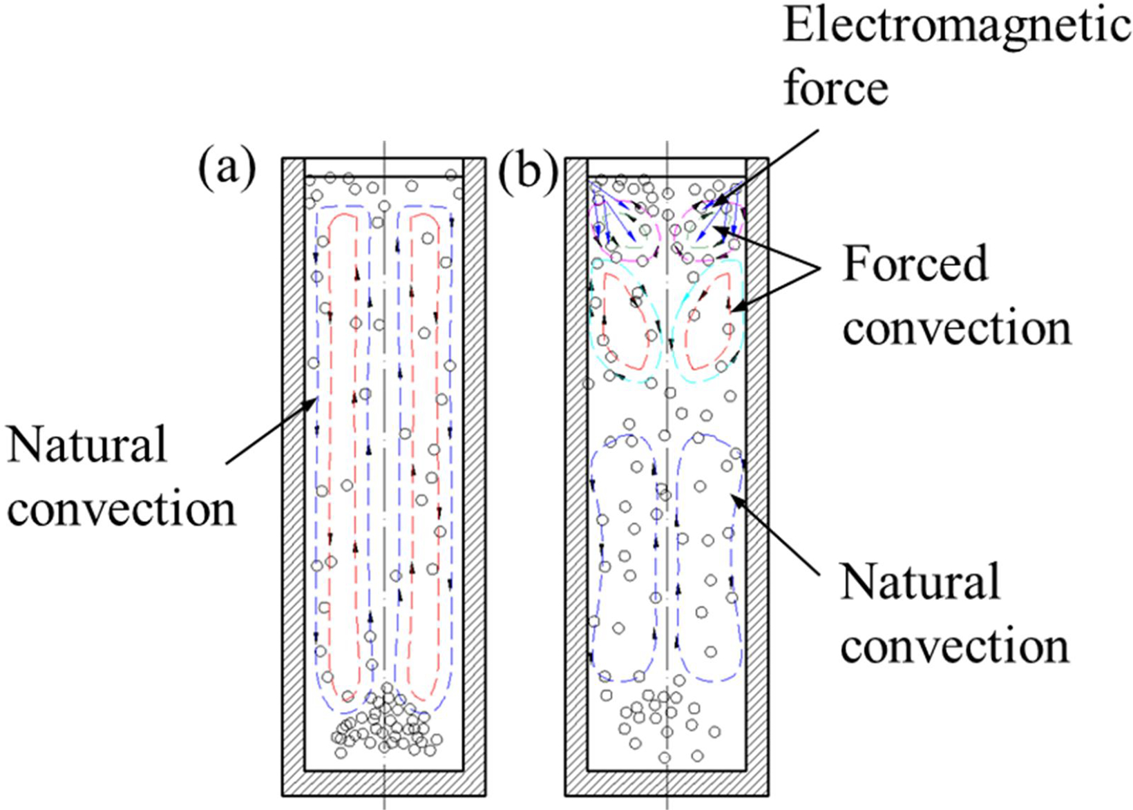
Illustration of nuclei movement in flow field of melt: a untreated, b treated
Effect of SPMO on carbon segregation
As is well known, carbon segregation is related to the flow field of melt and the relative movement between liquid and solid during solidification,19,20 both of which are altered by SPMO. On the other hand, without SPMO, solute builds up ahead of the liquid/solid interface, and it is practically impossible for solute to diffuse through the remaining liquid of the melt.With SPMO, however, the forced convection caused by the electromagnetic field increases solute transfer, thus reducing the concentration of carbon at liquid/solid interfaces, thereby reducing carbon segregation.
Effect of SPMO on shrinkage cavity
The formation of the shrinkage cavity depends on mainly the distribution of temperature within the melt.The forced convection produced by SPMO makes the temperature field more uniform in the melt. Moreover, Joule heat induced by the induction current affected the temperature distribution during the solidification process. Owing to skin effect, the induction current concentrates within the skin depth of the upper melt, so it continually heats the upper melt and delays its solidification. An untreated melt undergoes a process of sequence solidification (i.e. in sequential steps from outer to inner), while an SPMO treated melt undergoes bottom–up solidification (i.e. simultaneous solidification throughout the melt as a whole).
Conclusions
Our experimental results showed that, in 30Cr2Ni4MoV ingots with a low cooling rate that simulates the cooling rate of large scale ingots, SPMO treatment significantly affected the solidification process.
1. Carbon segregation was significantly reduced in the SPMO treated ingot.
2. The shrinkage cavity was concentrated into just the upper part of the SPMO treated ingot, but in the untreated ingot, the shrinkage cavity spreads into the lower part.
3. The size of grains was not affected significantly by SPMO.
Acknowledgements
The authors gratefully acknowledge the financial support from the National Basic Research Program of China (973 program, granted no. 2011CB012902), Shanghai government (granted no. 14DZ2261200). We thank Dr Tyler for editing the manuscript.