
Abstract
The effect of erosion angle on the erosion–corrosion interaction of Fe–3.5 wt-B alloy in flowing zinc was investigated. The total erosion–corrosion rate decreased linearly, whereas the pure erosion rate fluctuated slightly with increasing erosion angle, which was strongly dependent on the erosion–corrosion interaction. At an erosion angle of 0°, liquid zinc corrosion damaged the sample surface and facilitated erosion, which in turn increased corrosion via the removal of corrosion products. As the erosion angle increased, corrosion products accumulated and Fe2B flaked and cracked in front of the erosion interface, which resulted, in turn, in increased obstruction to the diffusion of liquid zinc. Accordingly, the erosion–corrosion interaction was reduced, thereby resulting in a low material loss at high erosion angles.
Introduction
Erosion–corrosion, in which the mechanical process of material removal through erosion and the chemical process of corrosion are coupled, is a serious problem in many industrial processes.1–3 Owing to the interaction of erosion and corrosion, the total erosion–corrosion rate of a component can exceed the sum of the individual rates of material loss from either of the two processes. The rate of material loss (i.e. total erosion–corrosion rate R) in an erosion–corrosion environment can be expressed as1,4,5
 ,
,  and
and  are the total material loss under erosion–corrosion conditions, as well as material loss stemming from mechanical erosion only, pure chemical corrosion only and the interaction between erosion and corrosion respectively.
Hot dip coating is an effective corrosion protection method, which is widely used in industrial applications.6,7 However, in a continuous galvanising line, the immersed bath equipment (e.g. sinker, stabiliser rolls, bearing, etc.) undergoes severe erosion–corrosion in flowing liquid zinc; this erosion–corrosion results from the flow velocity of the liquid zinc at the surface of the parts.8–10 The strong interaction between erosion and corrosion results in frequent downtime, maintenance and replacement of the severely corroded parts. Many new materials, which are corrosion resistant to liquid zinc, have recently been developed (such as Fe–B, W–Mo, Fe–Al, Fe–Si, etc.) in an attempt to prolong the service life of galvanising parts.7,8,11,12 Owing to its excellent corrosion resistance to liquid zinc, the Fe–B alloy containing 3.5 wt-B has significant potential for use in the parts of galvanising equipment. This excellent resistance stems from its unique structure (i.e. anticaustic Fe2B skeleton plus ductile iron matrix) and the non-wetting between the Fe2B and molten zinc; this anticaustic Fe2B skeleton generates an effective barrier effect to corrosion by liquid zinc.13–15
Many studies have shown that the erosion–corrosion interaction depends on the characteristics of the liquid, particle properties, flow field and the impact angle of the particles.4,16–19 For example, Burstein and Sasaki 19 reported that, compared to that acting at an erosion angle of 0°, the normal stress increased significantly at oblique erosion angle, thereby resulting in increased spallation of the corrosion products. The fresh metal surface was then exposed to the fluid and a further corrosion reaction occurred, thereby resulting in an enhanced corrosion reaction and, hence, a stronger erosion–corrosion interaction effect. In addition, erosion–corrosion experiments on 304L stainless steel showed that the erosion angle has a marked effect on the interaction. The change of particle impingement angle can also improve the pitting potential of the erosion surface and increase subsequent pitting corrosion, owing to the variation in erosion intensity; this increased pitting corrosion results in an increase in the severity of the corrosion reaction.16,20 The stronger intensified interaction results in accelerated material loss. Therefore, the erosion angle plays an important role in the erosion–corrosion process.
However, the effect of erosion angle on the damage mechanism of immersed bath equipment (e.g. sinker, stabiliser rolls, etc.) in flowing zinc remains unclear. Elucidating the role of erosion angle on the damage to the immersed bath equipment during the erosion–corrosion interaction in a flowing zinc bath is, therefore, essential. In the present work, the pure corrosion rate and total erosion–corrosion rates were measured via a static corrosion test in liquid zinc bath and an erosion–corrosion test in flowing zinc respectively. Based on previous study, 0.25 wt-Al addition to a static liquid zinc bath can result in a very slow corrosion rate for Fe–B alloy. 21 Furthermore, Liu et al. and Ghuman and Goldstein investigated the corrosion of various materials under static and dynamic conditions and pointed out that 0.30 wt-Al may lead to a proper reducing corrosion rate under dynamic condition.8,22 Considering these facts, the pure erosion rate, therefore, was assessed by performing the erosion–corrosion test in flowing zinc with 0.30 wt-Al addition (i.e. corrosion–inhibition). The erosion–corrosion interaction components are determined at various erosion angles. Furthermore, the erosion–corrosion interaction rate is also estimated, and the effect of erosion angle on the interaction of liquid zinc erosion and corrosion is discussed.
Material and methods
Materials and samples preparation
The investigated Fe–3.5 wt-B alloy was melted in a 10 kg capacity medium frequency induction furnace. In the early stage, clean pure iron, Fe–19.80 wt-B ferroalloy and steel scrap were added into furnace and then 0.10–0.15 wt-Al was appended to slag free molten steel in order to minimise the oxidation loss and slag formation. The melt was subsequently superheated to 1550–1600°C and then poured at 1420°C into a Y type sand mould to solidify the desired microstructures. Eventually, the as cast ingots were cleaned and cut into desired erosion–corrosion samples 120 × 15 × 5 mm by wire electric discharge machine. The chemical composition of the Fe–3.5 wt-B alloy analysed by spark emission spectrometer is shown in Table 1.
Chemical composition of the investigated Fe-3.5.B alloy/ Wt.
Erosion–corrosion test
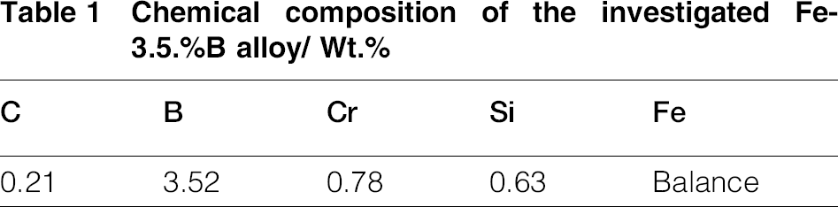
Figure 1a shows a schematic of the erosion–corrosion tester. A disc with six slots, for fixing the samples, was used to vary the erosion angles in 30° intervals; i.e. angles of 0, 30, 60 and 90° were considered, as shown in Fig. 1b. Before the erosion–corrosion test, the samples were ground with 2000 mesh carborundum paper and then washed with alcohol and acetone. The 5 h erosion–corrosion tests of the Fe–3.5 wt-B alloy in a 460°C liquid zinc bath, with and without 0.30 wt-Al, were performed under dynamic conditions, i.e. at a rotation speed of 60 rev min− 1. The erosion angle of flowing zinc on the sample surface was varied from 0 to 90° in 30° intervals. To ensure that iron in the liquid zinc was unsaturated, 30 kg pure zinc (99.99 wt-) was melted (i.e. the volume of liquid zinc is ∼4.6 × 10− 3 m3) in a silicon nitride in each erosion–corrosion test. Moreover, the total erosion–corrosion was obtained via an erosion–corrosion test in the flowing zinc bath. Based on the estimation equation of inhibition efficiency, 23 the inhibition efficiency of 0.30 wt-Al addition in flowing zinc bath is 89.37 at 460°C flowing liquid zinc. Therefore, the pure erosion rate was measured by the corrosion–inhibition test in flowing zinc with 0.30 wt-Al as the inhibitor. The pure corrosion rate was determined by performing the pure corrosion test in a 460°C static liquid zinc bath. The interaction of erosion and corrosion can be estimated at various angles.
a schematic map of erosion–corrosion testing device (1: rotation shaft; 2: disc for controlling erosion angle; 3: furnace; 4: sample holder; 5: crucible; 6: test sample; 7: liquid zinc) and b disc for controlling erosion angle
Characterisation
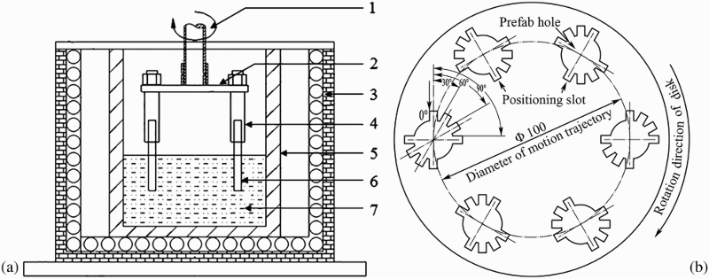
The schematic in Fig. 2 shows the measurement of the erosion–corrosion rate at various erosion angles (i.e. the one side thick loss measurement method). Before the erosion–corrosion tests, a standard line (as the dashed line shown in Fig. 2) was drawn along the center of the sample surface. The initial thickness between the standard line and the erosion surface of the tested samples was then obtained as the average of 12 values measured at multiple locations using a microscope. The zinc deposited on the edge of the erosion parts was removed after the erosion–corrosion tests. The thickness measurement between the standard line and the erosion interface of each erosion–corrosion sample was then measured microscopically at 1 mm intervals across the cross-section. The erosion–corrosion rate of the tested alloy was calculated from Refs. 8 and 13

Schematic illustration of erosion–corrosion rate measurement under erosion angle condition
The interfacial microstructure of the erosion–corrosion sample was carried out using a scanning electron microscopy (SEM), a backscattered electron image (Tescan VEGA II XMU, Brno, Czech Republic). The metallographic analysis of the as cast sample was performed on a LEICA DMI5000M. Phase analysis of the as cast sample was undertaken by X-ray diffraction in a MXP21VAHF diffractometer using copper Kα radiation coupling continuous scanning in a 2θ ranging from 20 to 100° with current flow of 200 mA and electric voltage of 40 kV and scanning speed of 2° min− 1 and step space of 0.02°.
Results and discussion
As cast microstructure
Figure 3 shows the as cast structure and X-ray diffraction pattern of the investigated Fe–3.5 wt-B alloys. The pattern reveals that the microstructure of the alloy is composed mainly of ferrite, as well as modest and small amounts of net-like eutectic Fe2B and Fe3C (as shown in Fig. 3) respectively. The eutectic Fe2B phase is homogeneously distributed throughout the metallic matrix.
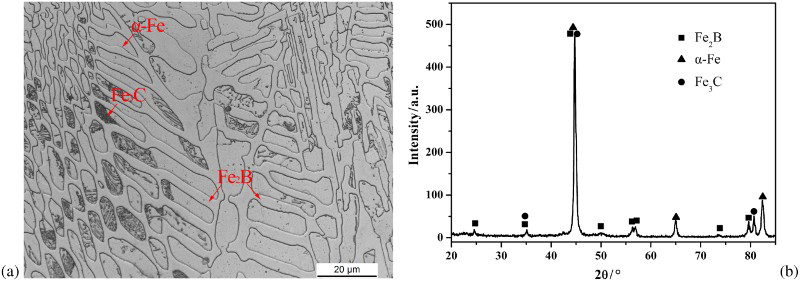
a as cast microstructure of Fe–3.5 wt-B alloy and b X-ray diffraction pattern
Effect of erosion angle on erosion–corrosion
Figure 4 shows the total erosion rate, pure erosion rate and pure corrosion rate as a function of the erosion angle at a liquid zinc temperature of 460°C, rotation speed of 60 rev min− 1 and test time of 5 h. As the figure shows, the erosion angle has a significant effect on the total erosion–corrosion rate, and the former decreases linearly increasing values of the latter. However, the pure erosion rate (as measured by the corrosion–inhibition test) changes only slightly, and very low damage is incurred, as the erosion angle increases. Figure 4 makes clear that increases in the erosion angle result in significant decreases in the total erosion–corrosion rate, but only slight variations in pure erosion rate. This indicates that the erosion angle of the flowing zinc has little impact on its micromechanical effect at the erosion surface. The rapid decrease in the total erosion–corrosion rate may be attributed to the interaction of erosion and corrosion. Moreover, the pure corrosion rate remains constant with increasing erosion angle (as shown in Fig. 4). The difference among the total erosion–corrosion rate, pure erosion rate and pure corrosion rate is also substantially reduced with increasing erosion angle. This implies that the increase in erosion angle significantly weakens the interaction of erosion–corrosion.
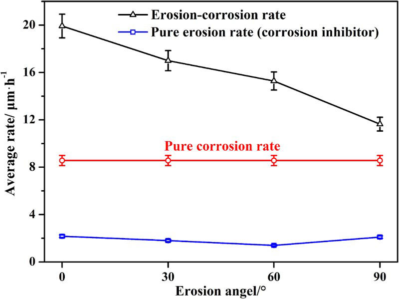
Erosion–corrosion components as function of erosion angle
Effect of erosion angle on erosion–corrosion behaviour of Fe–3.5 wt-B alloy
Figure 5 shows the erosion–corrosion interface morphologies of the Fe–3.5 wt-B alloy formed at various erosion angles of the 460°C flowing zinc bath. At an erosion angle of 0°, the 70 μm wide, residual anticaustic Fe2B skeleton is retained in front of the erosion interface. This retention stems from the corrosion effect and subsequent rapid mass transfer of the corrosion products under dynamic conditions (as shown in Fig. 5a). There are no products near the liquid zinc, and only a few are observed in areas beside the substrate. This implies that the massive, loose and blocky FeZn13, which formed first, is removed by the flowing zinc,7,13 thereby resulting in accelerated matrix loss of the Fe–3.5 wt-B alloy. Moreover, the residual Fe2B skeleton flakes and cracks owing to the shear stress produced by the flowing zinc. In this case, the barrier effect of Fe2B is weakened owing to early spallation. Therefore, the combined effect of corrosion product removal and Fe2B skeleton spallation results in further corrosion of the α-Fe matrix by the liquid zinc. This in turn leads to the re-formation of massive and loose corrosion products; this re-formation assists in accelerating the erosion process. Eventually, the erosion–corrosion process is significantly accelerated, which results in a large erosion–corrosion rate at an erosion angle of 0° (as shown in Fig. 4). Increasing the erosion angle to 30° results in a significant reduction of the residual anticaustic Fe2B skeleton zone and lessens the corresponding degree of spallation (as shown in Fig. 5b). This indicates that the intensity of erosion is substantially reduced with increasing erosion angle. In addition, as Fig. 5c and d shows, there is a preponderance of blocky and loose corrosion products at the front of the erosion–corrosion interface, and hence, only a few residual anticaustic Fe2B skeleton zones are observed. This implies that the erosion effect of flowing zinc is extremely weak leading, therefore, to a slowed transfer of corrosion products. Owing to the normal flow and impact of the liquid zinc, larger blocks of loose FeZn13 are observed at an erosion angle of 90°, compared to those at 60°. In this case, the corrosion product layer acted as a diffusion barrier that reduced the diffusion of liquid zinc atoms, thereby retarding the Fe/Zn corrosion reaction. This retardation, in turn, reduced the erosion–corrosion interaction, owing to the reduction of erosion intensity with increasing erosion angle. Consequently, the minimum total erosion–corrosion rate is obtained at an erosion angle of 90° (as shown in Fig. 4).
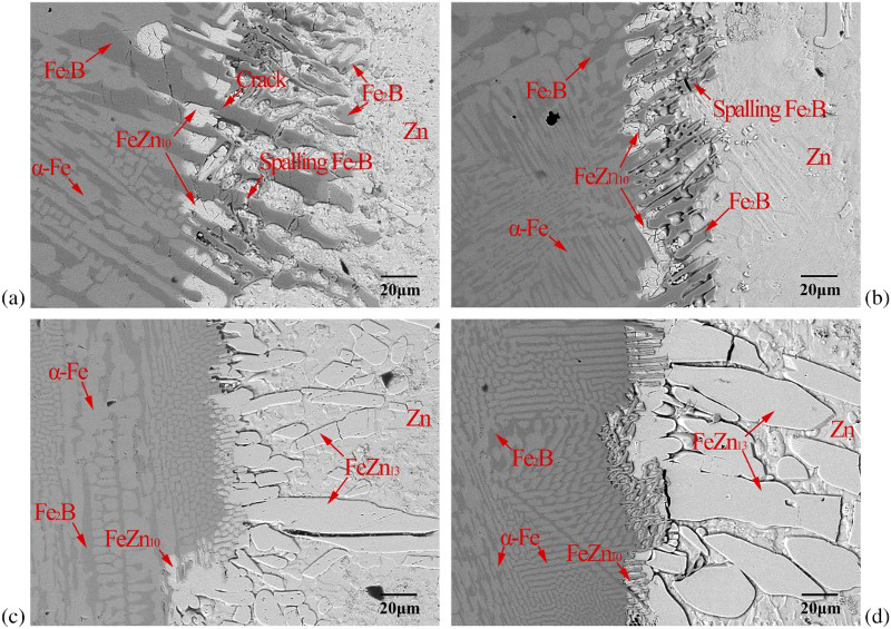
Interfacial morphologies of Fe–3.5 wt-B alloy in 460°C flowing zinc bath at a 0°, b 30°, c 60°, d 90° erosion angles
At oblique erosion angles, the micromechanical effect of flowing liquid on the sample surface can be classified into two categories, namely, shear stress and normal stress (as shown in Fig. 6).17,19 At an erosion angle of 0°, the strong shear effect destroys the erosion–corrosion layer via the accelerated removal of corrosion compounds and spallation of the residual Fe2B skeleton. The corrosion reaction then proceeds rapidly, which in turn promotes the further removal of corrosion products. As the erosion angle increases, the flowing zinc strikes the surface of the sample, and its tangent velocity is reduced. This results in reduced shear stresses along, and normal stresses perpendicular to, the surface compared to those acting at an erosion angle of 0°. As a result, the mass transfer decreases sharply, and the spallation degree of the residual Fe2B skeleton is also reduced. At an erosion angle of 90°, the flowing zinc arrives perpendicularly at the surface, and the velocity along the sample surface is extremely low, i.e. only normal stresses act on the sample surface, and massive corrosion products accumulate in front of the erosion–corrosion interface. These products act as a barrier layer, which hinders the diffusion of liquid zinc, retards the Fe/Zn corrosion reaction and thereby affects the erosion–corrosion process. In addition, with the extremely weak shear effect at 90°, the spallation of the Fe2B skeleton may have resulted mainly from cracks formed owing to the differing thermal expansion coefficients of the various phases.13,24 Based on the above analyses, the subdued shear effect and intensified normal impact result in a slow transfer of corrosion products, reduced spalling of the Fe2B skeleton as well as intensity of the erosion–corrosion process. Therefore, the total erosion–corrosion rate decreases with increasing erosion angle.
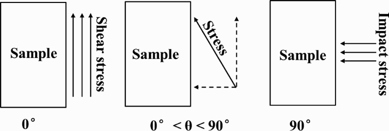
Schematic diagram of micromechanical effect of flowing zinc at various angles
Corrosion effect in erosion–corrosion process at various angles
Previous investigations indicated that the static corrosion rate can be considered as the pure corrosion component of the erosion–corrosion interaction.25,26 The pure corrosion rates in Fig. 4 remained constant owing to uniform dissolution corrosion. The SEM image in Fig. 7 shows the FeZn10, loose FeZn13 and spalled Fe2B skeleton, which comprise the corrosion product zone at the interface of the Fe–3.5 wt-B alloy in 460°C static liquid zinc (Fig. 7). The accelerated transfer of corrosion products occurs readily under dynamic conditions. Cracks also form on the net-like Fe2B skeleton owing to the differing thermal expansion coefficients of the various phases in the corrosion interface. Therefore, compared to its static counterpart, the flowing zinc has a greater micromechanical effect on, and result in accelerated spallation of, the net-like Fe2B skeleton. The barrier effect of the Fe2B skeleton to zinc diffusion is therefore reduced, and the intensity of the corrosion process increases. Accordingly, the formation of the corrosion product layer and cracks in the Fe2B skeleton result in increased erosion and an accelerated corrosion reaction; this, in turn, results in accelerated material loss at various angles.
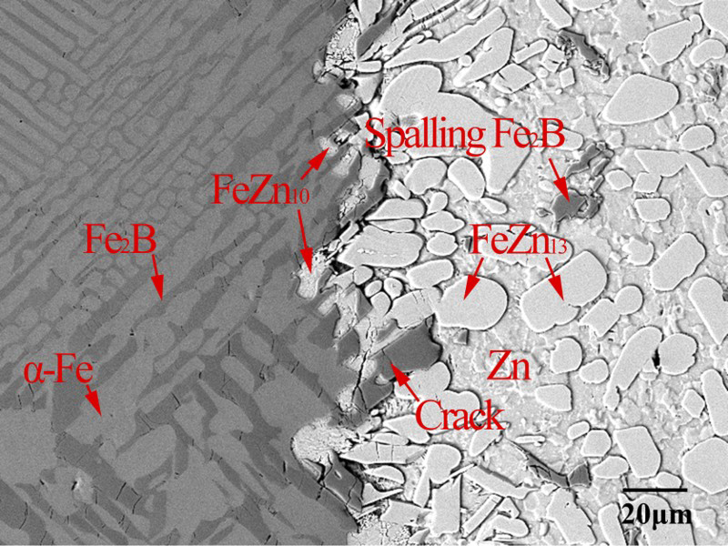
Interfacial morphology of Fe–3.5 wt-B alloy in 460°C static liquid zinc
Effect of erosion angle on pure erosion behaviour of Fe–3.5 wt-B alloy
In the present work, the pure erosion rate changes only slightly with increasing erosion angle (as shown in Fig. 4). This indicates that the micromechanical effect of flowing zinc is relatively insensitive to changes in the erosion angle. Figure 8 shows the interfacial morphologies of Fe–3.5 wt-B alloy obtained at various erosion angles of flowing liquid zinc with 0.30 wt-Al addition (i.e. under corrosion–inhibition conditions). As Fig. 8a shows, at an erosion angle of 0°, a continuous and uniform inhibition layer (i.e. the Fe2Al5 phase) formed beside the substrate of the alloy, in front of the erosion/corrosion interface. The iron matrix is barely corroded by the liquid zinc. This indicates that the corrosion reaction of α-Fe matrix and liquid zinc can be significantly inhibited by adding 0.30 wt-Al to the flowing zinc bath. Furthermore, the somewhat spalled Fe2B skeleton and broken inhibition layer, observed in front of the erosion layer, may be attributed to the shear effect produced by the flowing zinc. The inhibition layer thinned gradually and eventually broke (as shown in Fig. 8b and c) as the erosion angle increases from 0 to 60°; this thinning resulted from the coaction of the decreasing shear stress and intensified normal stress, which led to a reduction in the pure erosion rate. At an erosion angel of 90°, the inhibition layer fractured, and the anticaustic Fe2B skeleton underwent spallation (Fig. 8d) in front of the erosion interface. This fracture and spallation may be attributed to the strong normal impact of the flowing zinc.
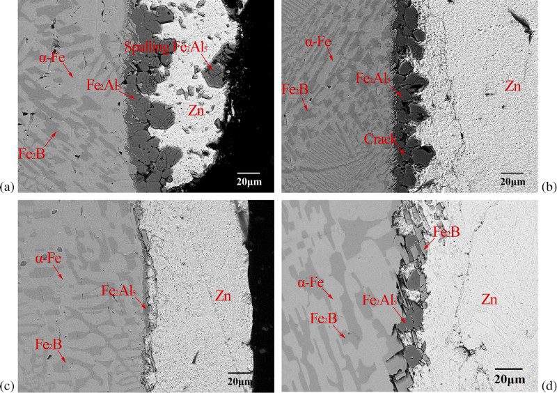
a 0°; b 30°; c 60°; d 90°Interfacial morphologies of Fe–3.5 wt-B alloy in 460°C flowing zinc bath with 0.3 wt-Al addition at various erosion angles
The inhibition layer greatly suppresses the corrosion reaction between the α-Fe matrix and the zinc and thereby limits the fragmentation and spallation of the Fe2B skeleton; this, in turn, results in a low material degradation rate of the Fe–3.5 wt-B alloy in the flowing zinc bath with 0.30 wt-Al addition (Fig. 4). The above result also indicates that the Fe–3.5 wt-B alloy in flowing zinc is most severely damaged under pure erosion conditions (as shown in Fig. 4) via the action of the maximum shear or normal stress. However, the pure erosion rate varies only slightly with erosion angle. This confirms that the reduced total erosion–corrosion rate results from variations in the erosion–corrosion interaction; variations in the interaction stem from changes in the erosion angle.
Effect of erosion angle on erosion–corrosion interaction of Fe–3.5 wt-B alloy in flowing zinc
Based on equation (1) and Fig. 4, the erosion–corrosion interaction rate can be estimated at various erosion angles (as shown in Fig. 9). Changes in the erosion angle have a pronounced effect on the erosion–corrosion interaction rate. For example, the interaction rate decreases slowly with increasing erosion angle of up to 60° and rapidly thereafter. The erosion–corrosion interaction can, in general, be classified as erosion enhanced corrosion and corrosion enhanced erosion 4 . Figure 10 illustrates, schematically, the erosion–corrosion interaction mechanism of Fe–3.5 wt-B alloy in flowing zinc, for erosion angles of 0 and 90°. At an erosion angle of 0°, the shear and normal flow accelerate the removal of corrosion products and spallation of the anticaustic Fe2B skeleton (as shown in Fig. 10b). The fresh α-Fe matrixes of the alloy are subsequently exposed to the aggressive flowing zinc bath, which may induce a further corrosion reaction (i.e. erosion enhanced corrosion). This violent corrosion reaction results in the further formation of corrosion products, which in turn increases the removal of corrosion products and interfacial damage; i.e. this violent corrosion reaction can be considered as corrosion enhanced erosion. However, the subdued shear effect and intensified normal impact resulted in reduced spallation of the residual Fe2B and a reduction in the removal rate of corrosion products with increasing erosion angle. The accumulation of corrosion products and filled-in Fe2B skeleton can hinder the diffusion of zinc diffusion, thereby resulting in reduced erosion enhanced corrosion and corrosion enhanced erosion. At high erosion angles (i.e. 90°), flowing zinc arrives perpendicularly at the sample surface and the shear effect is negligible; this suggests that the flow accelerated transfer process is sharply reduced (as shown in Fig. 10c). The strong normal impact of the flowing zinc should also lead to an accumulation of mass corrosion products in front of the erosion interface (as shown in Fig. 10d). Therefore, at an erosion angle of 90°, both the erosion enhanced corrosion and corrosion enhanced erosion should decrease even more sharply than at 0°, and hence, the erosion–corrosion interaction decreases significantly.
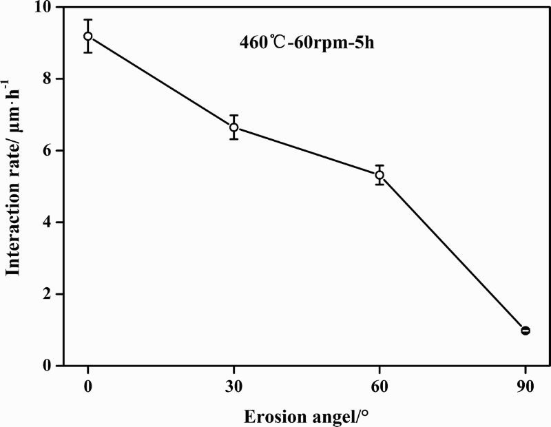
Erosion–corrosion interaction rate as function of erosion angle
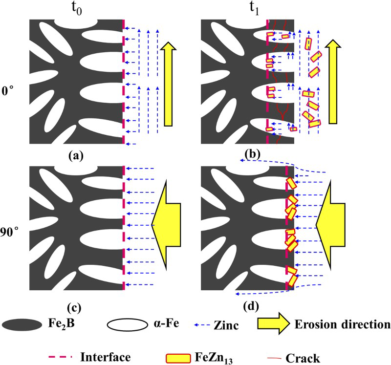
a t1: 0°; b t2: 0°; c t1: 90°; d t2: 90°Representation of erosion–corrosion interaction mechanism of Fe–3.5 wt-B alloy in flowing zinc at 0 and 90° (time: t1 ≤ t2)
Figure 11 compares the contributions of individual factors (i.e. pure corrosion, pure erosion and the interaction between the two) to the total erosion–corrosion rate of Fe–3.5 wt-B alloy at different erosion angles of the flowing zinc bath. As the figure shows, the contribution of the interaction rate to the total rate decreases significantly from 46.14 to 8.44, as the erosion angle increases from 0 to 90°; in contrast, the contribution of the pure corrosion rate increases rapidly from 42.97 to 73.52. Moreover, the contribution of pure erosion ranges from only 9.16 to 18.04. Figure 11 reveals that, at low erosion angles, the pure corrosion and erosion–corrosion interaction both control the material loss of the Fe–3.5 wt-B alloy in flowing zinc. With increasing erosion angle, the combined action of decreased shear stress and intensified normal stress result in filled-in Fe2B skeletons and an accumulation of corrosion products; this in turn leads to an intensified corrosion reaction and reduced erosion–corrosion interaction. Therefore, with increasing erosion angle, the pure corrosion rate becomes the dominant factor, which results in material loss of the Fe–3.5 wt-B alloy.
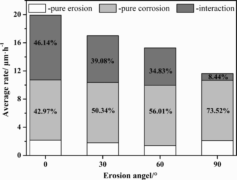
Percentage of pure erosion, pure corrosion and interaction to total erosion–corrosion rate as function of erosion angle
Conclusions
This study focused on the effect of erosion angle on the interaction of erosion and corrosion of Fe–3.5 wt-B alloy in a liquid zinc bath; the present work supports the following conclusions.
The total erosion–corrosion rate of Fe–3.5 wt-B alloy decreases linearly, whereas the pure erosion rate fluctuates only slightly with increasing erosion angle; the total rate is strongly dependent on the erosion–corrosion interaction.
The erosion angle has a significant effect on the interface microstructure and damage of the Fe–3.5 wt-B alloy. In fact, the erosion–corrosion rate of the alloy in flowing zinc decreases significantly with the increase in erosion angle.
The corrosion resulting from the flowing liquid zinc roughens the surface and facilitates flowing erosion. This erosion increases the corrosion, owing to the removal of corrosion products at low erosion angles. In contrast, at higher erosion angles, corrosion products accumulate and Fe2B flakes and cracks form in front of the erosion interface, thereby leading to a reduced erosion–corrosion interaction.
Footnotes
Acknowledgements
The authors would like to appreciate the financial support for this work from the Natural Science Foundation of China (grant nos. 51301128 and 51271142), the Specialized Research Fund for the Doctoral Program of Higher Education of China (grant nos. 20120201120005 and 20110201130008), the National Science Foundation for Post-doctoral Scientists of China (grant nos. 2012M521767 and 2013T60875), the Natural Science Foundation of Shaanxi Province (grant no. 2014JQ7281) and the Shaanxi provincial post-doctoral research project and Fundamental Research Funds for the Central Universities (grant nos. XJJ2013038 and XJJ2014167).