
Abstract
Based on a novel calculation model that considers microstructural changes and latent heat release, evolution of heat transfer coefficients of boron steel in different metallographic states during hot forming die quenching are investigated. Results demonstrate that the evolution of the coefficients in the different metallographic states is significantly different in each state. As blank temperature decreases, no evident fluctuations emerge in the austenitic state, a significant sharp increase followed by a gradual decrease is detected in the multiphase state during martensitic transformation and a slight decrease is observed in the martensitic state. A simulation model for temperature predicting is established by integrating the coefficient data with the finite element software ABAQUS. The numerical results showed good agreement with the experimental results.
Keywords
Introduction
The use of ultra high strength steel parts with a high strength/weight ratio, which helps to achieve the important aim of reducing vehicle weight without compromising crash performance, is being increasingly applied in the automobile industry.1,2 Hot forming die quenching (HFDQ), also known as hot stamping or press hardening, is the main forming method for these ultra high strength steel products.3,4 In this process, the blank is preferably heated to an austenitising temperature of above 900°C, and then moved to the dies, which have a cooling system, immediately. In the cold dies, sheet forming and quench hardening occur simultaneously, and the metallographic state of the blank is transformed from austenite to martensite gradually. Parts with ultimate tensile strengths up to 1500 MPa can be obtained in this way. 5
Hot forming die quenching is a thermomechanical forming process with phase conversion. Thermal and microstructural parameters complicate the description of the mechanical phenomena of the process. It is difficult to develop a meticulous research only through experiments. Numerical simulation is a powerful and effective tool to predict complex forming problems and to optimise the final component properties. A realistic simulation for HFDQ requires accurate modelling of the thermal behaviour because the microstructure and properties of the components will be related to both the temperature profile and the deformation during the process. The heat transfer coefficient (HTC) is responsible for the thermal behaviour and governs the cooling of the blanks throughout the whole forming operation; it is therefore one of the most important characteristics that has to be taken into account in the simulation of the HFDQ process.
Investigations of HTCs between the blank and the dies in the HFDQ process have been conducted by a number of researchers using two main methods: an experimental analytic method and an inverse simulation method. Merklein et al.6,7 performed a quenching test with a heatable quenching tool and calculated the HTC that was dependent on the contact pressure and the gap distance using a computational model derived from Newton's cooling law. Rosochowska et al. 8 proposed a novel method of measuring the thermal contact conductance based on uniform heat flow through the upper heated tool, the test specimen and the lower cooled tool. Li et al. 9 expounded that the HTC calculation was an inverse heat conduction problem and applied a finite element method, an advance retreat method and a golden section method in the calculation of HTC. Caron et al.10,11 investigated HTC variations during different phases of a hot stamping experiment as functions of the stamping pressure and the temperature difference between the blank and the dies through inverse heat conduction analysis. Salomonsson et al. 12 used an elementary inverse simulation approach to predict the HTCs of different steels (uncoated 22MnB5 steel and Al–Si coated Usibor 1500P steel) under different process conditions; their results showed that the variable HTC gives a better match to experimental data and that the rough surface that the Usibor 1500P steel developed after heating reduced the real contact area and resulted in a relatively smaller HTC compared to the uncoated 22MnB5 steel. Hu et al. 13 investigated the effect of oxide scale on temperature dependent interfacial heat transfer in the hot stamping process. The similarities and the differences of the two approaches for calculating HTCs were outlined and commented on by Bosetti et al. 14
The aforementioned contributions offer a good understanding of the HTC variations under different process conditions and various forming stages. However, little work has been reported on HTC evolution in different metallographic states during HFDQ. Phase transformation from austenite to martensite occurs with the fast cooling in the quenching process. Material characteristics, e.g. specific heat, do not remain constant in different metallographic states and neither does the heat transfer behaviour. 15 Owing to geometry, different regions of a part are quenched under different contact pressures, which influence the heat conduction behaviour through the effective contact areas. In addition, parts with the same geometry will encounter various initial die surface temperatures during the recycled production process. Therefore, contact pressure and initial die surface temperature are two practical factors that will influence the heat transfer behaviour between the blank and the dies. In view of the aforementioned analysis, the HTC evolution of boron steel in different metallographic states during HFDQ and the effects of contact pressure and initial die surface temperature will be the subjects of the present paper. To achieve the target, a novel calculation model that considers microstructural changes and latent heat release will be introduced. The present work will be beneficial to aid understanding of the heat transfer behaviour in different metallographic states during the HFDQ process, and the coefficient evolution data could be applied to the simulation of HFDQ for a precise prediction of temperature profiles. The precise temperature prediction for HFDQ will be favourable to the die design and the process parameters setting. Then, the blank temperature can be better controlled, and quenched parts with complete martensitic microstructure and ultra high strength can be achieved.
Methodology
Experimental apparatus
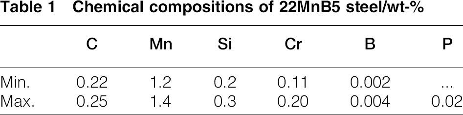
The experimental apparatus for simulating the HFDQ process is presented schematically in Fig. 1. To simplify the analysis, deformation of the blank was neglected. The set-up was mainly composed of two flat dies with instrumented cooling ducts and 100 × 50 mm blanks with thicknesses of 2.0 mm. The material of the blank was uncoated 22MnB5 steel supplied by Baosteel (China). The chemical compositions of the boron steel are shown in Table 1. Temperatures of the blank were measured by two K type thermocouples soldered in the 1.0 mm diameter holes drilled on the sidewall of the blank. The material of the dies was an H-13 hot work tool steel. The die surface temperatures were monitored by the K type thermocouples placed 0.3 mm from the die surface, perpendicular to the flat surface. All the K type thermocouples were connected to a multichannel data acquisition system, and the recording frequency was set to 10 Hz, so a set of temperature data could be obtained every 0.1 s. Pressures of the apparatus were controlled by a hydraulic pump with a maximum pressure of 60 MPa and a regulating fineness of 0.1 kPa. The different initial die surface temperatures were simply adjusted through the heat conductance between the dies and the heated metal bulks placed on the dies. The metal bulks could be commodity steels such as Q235. To ensure sufficient contact between the blank and the dies and a uniform pressure distribution, the surfaces of the blanks and the dies were set to Ra = 0.2 μm by fine grinding, and the levelness of the apparatus was adjusted using a spirit level. The coolant was water at room temperature.
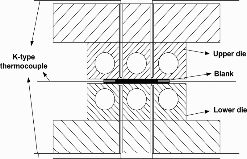
Schematic of HFDQ experimental apparatus
Chemical compositions of 22MnB5 steel/wt-
To determine the HTCs under different quenching conditions, the blanks were preheated to 950°C for 5 min to achieve homogeneous austenitisation. Then, the heated blanks were taken out of the furnace, and when the blank temperature decreased to a little more than 800°C, the blanks were transferred to the cooled dies immediately and the dies closed simultaneously. The blanks would be quenched in the dies under different contact pressures from 1 to 10 MPa with 20°C initial die surface temperature and various initial die surface temperatures from 20 to 200°C with 1 MPa contact pressure respectively. The average values measured by the thermocouples were taken as the temperatures of the blank and the die surfaces.
Thermal computation model
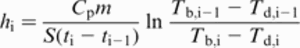
Determination of HTC
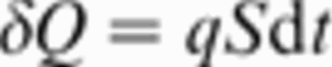
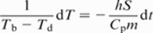
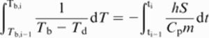
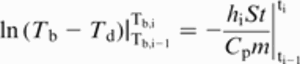
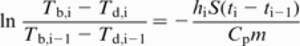
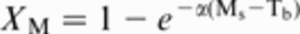
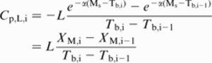
During quenching, the heat loss δQ can be defined when the blank temperature decreases by dTb in time dt as

According to the definition of the heat flux density q, which is the amount of transferred heat between the two contact partners per area per time, δQ can also be expressed as
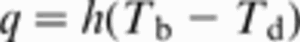
According to Newton's cooling law, q can be calculated as
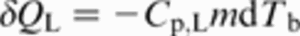
Assuming that the heat loss of the blank is totally absorbed by the dies, the following equation can be gained based on the first law of thermodynamics

Effective specific heat
When the cooling rate of the specimen in the austenitic state is higher than 27 K s− 1, martensitic transformation will occur, and the material's characteristics will change.
16
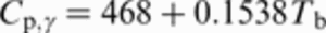
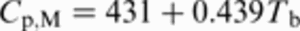
One of the most obvious changes is the variation of specific heat. Hay et al.
15
summarised the laws of specific heat of the boron steel, in the austenitic state Cp,r and in the martensitic state Cp,M, changing with blank temperature as
Martensitic transformation is a non-diffusion type of transformation. Martensite fraction is only a function of blank temperature, which can be calculated based on the Koistinen–Marburger law
18
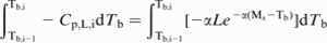
By applying equation (13) to equation (12), the following equation can be obtained


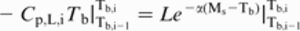
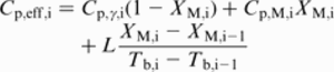
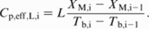
In conclusion, the instantaneous HTC during HFDQ can be calculated as


Experimental results and verification
Figure 2 shows the temperature–time data recorded under different pressure and initial die surface temperature conditions. It can be seen that the blank cools faster at higher pressures and lower die surface temperatures. In addition, a slope change occurs when the blank temperature decreases at ∼411°C, which is related to the latent heat originating from the martensitic transformation.
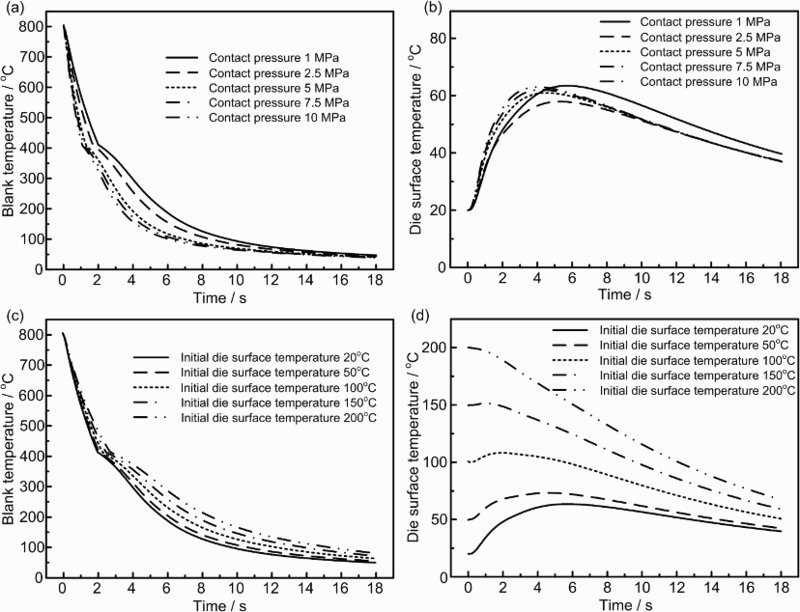
Experimental temperature data: a blank temperature and b die surface temperature profiles at various pressure conditions, c blank temperature and d die surface temperature profiles at various initial conditions
The cooling rates of the blanks during HFDQ in the temperature range of 800–200°C are plotted in Fig. 3. Obviously, almost all the cooling rates in the investigated pressure and initial die surface temperature ranges significantly exceed the critical value of 27 K s− 1 for martensitic transformation. Therefore, the rapid cooling in the current work was sufficient to prevent phases other than martensite from forming. The metallograph presenting a fully martensitic microstructure in Fig. 4 also confirms this conclusion.
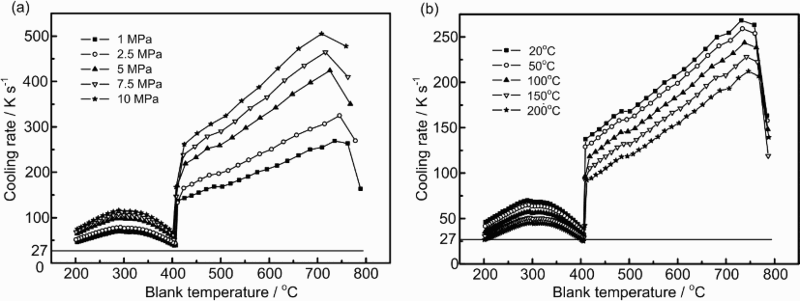
Variations of blank cooling rate under various a pressure and b initial die surface temperature conditions
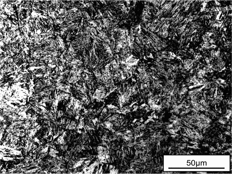
Microstructure of specimen after HFDQ at 1 MPa contact pressure, 200°C initial die surface temperature
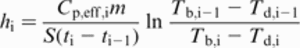
One method to examine the effectiveness of the computational model is to compare the deviation between the simulation and the experimental results by integrating the model using finite element software.13,19,20 To verify the applicability of the HTC calculation approach in the present work, a temperature prediction model was established with the software ABAQUS-6.12, as shown in Fig. 5a. Because the model was centrosymmetric, a one-fourth scale model was created. Pressure dependent HTCs were integrated into the interaction module to illustrate the contact behaviour of the model. Latent heat release during martensitic transformation was taken into account by applying the temperature dependent effective specific heats in the material module of the model. The boundaries of the simulation were consistent with the actual test conditions. Purely thermal analysis was performed in the simulation. The simulation results of the temperature evolution and comparisons with the experimental results are shown in Fig. 5b. The good agreements between the measured and the calculated temperature variations verified the correctness of the calculation model and illustrated that the HTC calculation model can be applied to the prediction of temperature profiles in HFDQ.
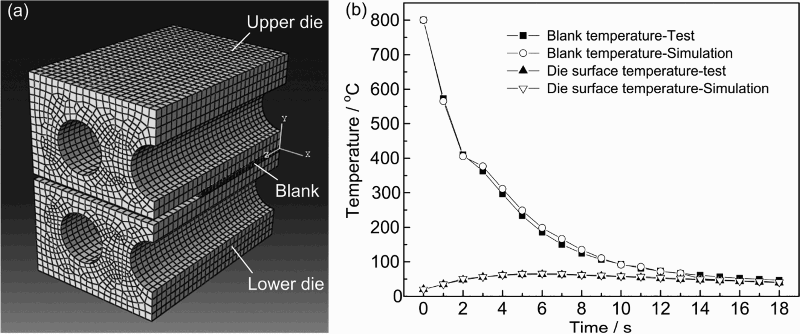
a finite element model and b comparison of simulation and experimental temperature profiles at 1 MPa contact pressure, 20°C initial die surface temperature
Analysis and discussion
The evolution of the HTC and the martensite fraction at 1 MPa contact pressure and 20°C initial die surface temperature are plotted as a function of blank temperature in Fig. 6. According to the characteristics of the HTC and the microstructure varying with blank temperature, the evolution of the HTC during HFDQ can be divided into three distinct stages: the stable stage, the violent fluctuation stage and the gradient decreasing stage, which correspond to the austenitic, the multiphase and the martensitic states respectively. These variations can be explained in combination with the change of specific heat, as shown in Fig. 7. The analysis is given below.
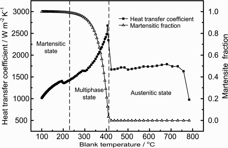
Evolution of HTC and martensite fraction with blank temperature during HFDQ at 1 MPa contact pressure, 20°C initial die surface temperature
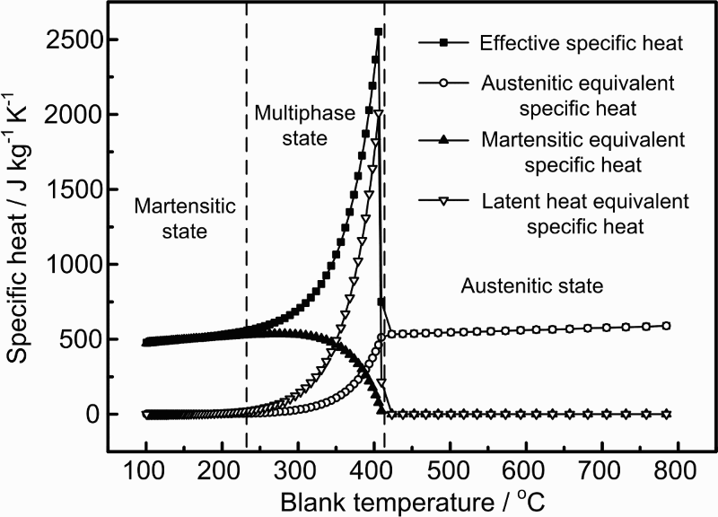
Evolution of effective specific heat with blank temperature
Austenitic state
The blank temperature range corresponding to the austenitic state is 800–411.3°C, as seen in Fig. 6. It can be seen that no evident fluctuations of HTC evolution appear in the austenitic state. As shown in Fig. 7, the effective specific heat in this stage mainly depends on the austenitic equivalent specific heat, which changes little with blank temperature falling. In addition, the ratios of the temperature differences between the blank and the dies are stable, which can be calculated from the recorded temperature data. Therefore, a steady HTC variation trend occurs in this stage. The increase in HTC during the initial period of the blank cooling is mainly due to the unstable heat conduction originating from inadequate contact between the blank and the dies.
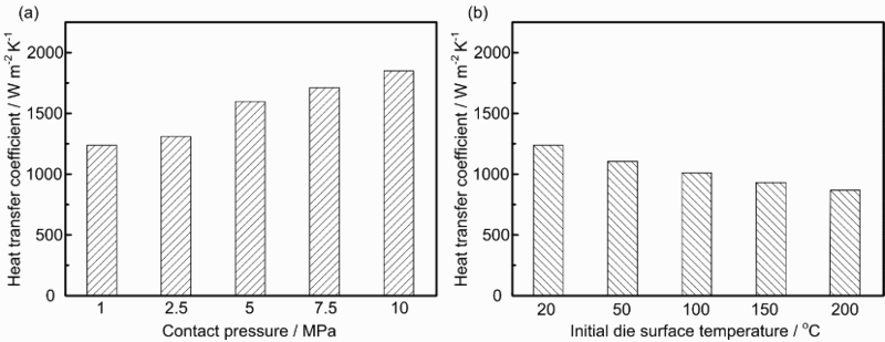
The average HTCs for the investigated pressures and initial die surface temperatures are presented in Fig. 8. The variation of the data shows that, as the contact pressure increases and the initial die surface temperature decreases, the HTC increases. However, a more noticeable contact pressure dependence is detected. Because specific heat is a physical property of steels, differences in the average HTCs under various quenching conditions result from the influences of the conditions on the temperature change of the blank and the dies.
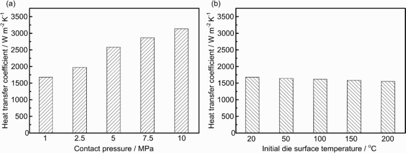
Comparison of average HTCs under different a pressure and b initial die surface temperature conditions in austenitic state
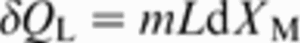
Multiphase state
The blank temperature range corresponding to the multiphase state is 411.3–230°C, as shown in Fig. 6. Transformation from the austenitic state to the martensitic state occurs in this multiphase state, resulting in a reduction of austenite and an increase in martensite. Variations of the HTC in this state are obvious, and the values are significantly higher than for the other two states. Two main aspects are related to these characteristics, namely, the microstructural changes and the latent heat release. On the one hand, the martensitic specific heat is greater than the austenitic specific heat in the temperature range of 411.3–230°C, which can be calculated using equations (10) and (11); the decreased austenite transfers to martensite, leading to an increase in the effective specific heat. On the other hand, the martensitic conversion releases a large amount of heat, resulting in a sharp growth in the effective specific heat, as shown in Fig. 7. These two factors cause the blank to release a much larger amount of heat at the same temperature change as in the other two states, while the latter plays a more important role. The decrease in the HTC after a rigid growth with blank temperature falling is a consequence of the decrease in latent heat release with progressive phase transformation.
Figure 9 shows the calculated HTCs as functions of blank temperature, at various contact pressures and initial die surface temperatures. As seen from Fig. 9a, the contact pressure strongly influences the variation of HTC. As the pressure increases, not only does the maximum HTC value increase, but also the HTC values during the overall period and the growth rate to the peak increase. It can be seen from Figs. 2 and 3 that the process was more efficient at higher pressures when the blanks were cooled to the same temperature. According to the HTC calculation equation (21), a smaller denominator of time interval will lead to a greater HTC. Consequently, the HTC at a higher pressure in the same blank temperature range is greater, owing to a shorter time interval, although the specific heat and the martensitic fraction under different quenching conditions remain constant at the same blank temperature. Higher HTCs with lower initial die surface temperatures can be seen in Fig. 9b, but the effect is slightly less noticeable than that of pressure. The diversity of HTCs at different initial die surface temperatures is mainly attributed to the temperature difference between the blank and the contact medium and the temperature change rate of the system.
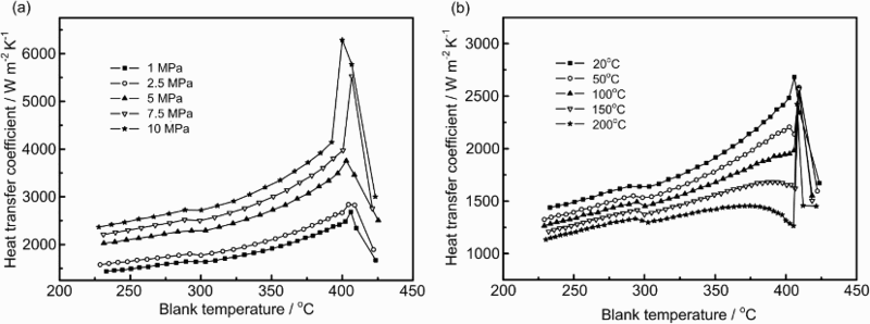
Evolution of HTC at various a pressure and b initial die surface temperature conditions in multiphase state during martensitic transformation
Martensitic state
The blank temperature range corresponding to the martensitic state is 230–100°C, as seen in Fig. 6. The variation of HTC in this state shows a slightly decreasing trend. This is because the martensitic transformation is finished, and there are no other phase transformations. The decreasing trend is mainly related to the diminishing temperature difference between the blank and the dies. The average HTC evolution, depending on contact pressure and initial die surface temperature, is shown in Fig. 10. The effects of the two factors on HTC in the martensitic state are observed to be similar to those in the austenitic state.
Comparison of average HTCs at various a pressure and b initial die surface temperature conditions in martensitic state
Conclusions
A novel calculation model that considers microstructural changes and latent heat release has been established; based on this model, the evolution of the HTCs of boron steel in different metallographic states during HFDQ has been investigated. In addition, the effects of contact pressure and initial die surface temperature on the HTCs in the austenitic state, the multiphase state during the martensitic transformation and the martensitic state have been studied. By integrating the model with the finite element software ABAQUS, a temperature prediction model for HFDQ has been created. The good agreement between the numerical and the experimental results confirms the applicability of the HTC calculation model in the prediction of temperature profiles in HFDQ. The conclusions of the present paper are as follows.
Heat transfer coefficient evolution is closely related to the effective specific heat variation. The latent heat release from the austenite to martensite transformation in HFDQ causes the effective specific heat to change during the HFDQ process. This variation of the effective specific heat leads to significant differences between the HTCs in different metallographic states during HFDQ. As blank temperature decreased, no evident fluctuations of the HTCs emerged in the austenitic state; a significant sharp increase followed by a gradual decrease was detected in the multiphase state during martensitic transformation, and there was a slight decrease in the martensitic state. With increasing contact pressure and decreasing initial die surface temperature, the HTCs of all the metallographic states of HFDQ increased, with the effect of contact pressure being more noticeable.
Acknowledgements
The present work was supported by the Major Technology Program of Ministry of Industry and Information Technology of China (grant no. 2009ZX04014-072-01) and the Technology Development Program of Jilin Province (grant no. 20130102021JC).