
Abstract
A fatigue model based on entropy generation is presented and validated through experiments. This model is purely physical and combines statistical mechanics with thermodynamic laws applied at a local scale. The model does not require an empirical damage surface or phenomenological constitutive modeling constants. Damage evolution parameter varies from 0 to 1. As it is for the irreversible internal entropy production, this parameter is a non-decreasing quantity that increases with the degradation of a material.
Introduction
All components and structures subjected to cycling loading are prone to fatigue failure. Microcrack formation, coalescence and growth weaken the specimen and lead to final failure, which is referred as fatigue, especially when the specimen undergoes cyclic loading. Many attempts have been made to define and predict the fatigue evolution of materials in different circumstances,2–8 and the well known Coffin–Manson law is one them. Solely, based on experimental data, the Coffin–Manson model relates the amplitude of the applied cyclic plastic deformation to the number of cycles to failure. This model has been proven to be reliable for low cycle fatigue regime, and the universality of this law leads us to consider that there might be a general physical process that governs the observed fatigue phenomenon.1–25 However, the Coffin–Manson and similar phenomenological models are empirical and do not give a clue about the physical process underlying fatigue mechanism.
Mechanical properties of materials have been studied in different length scales of continuum,26,27, mesoscales 28 and microscale.29,30 As the length scale becomes smaller, more details are included. However, the required computational resources increase, and the size of the simulated sample usually decreases. Hence, for practical purposes, the continuum models should be incorporated.
Materials experience low cycle fatigue when subjected to plastic deformation and undergo high cycle fatigue when subjected to elastic deformation only. It is possible to explain fatigue based on thermodynamic principles. If any component or structure is considered to be a thermodynamic system, it cannot be 100 efficient; as such, it must have a limited life span. It is also possible to explain fatigue at the atomic scale, and while this is very easy and obvious in the low cycle fatigue regime, it is more complex in the high cycle fatigue regime. According to continuum mechanic rules in the elastic region, when the material is unloaded, it does not experience any permanent deformation, and the stress–strain diagram goes back to the origin. However, this is not true when we inspect the material at the atomic scale. In the elastic region under cycling loading when atomic bonds are stretched after unloading, atoms do not necessarily go back to their initial lattice site but to a site that is at a lower energy level. 33 This energy minimization process is responsible for initiating nanoscale voids in the material. Of course, these voids cause stress concentration points, and as a result, nanoscale voids grow and coalesce to form microscale voids (cracks). Overtime, microcracks grow and coalesce into bigger cracks, and eventually, load carrying intact cross-section is subjected to a stress beyond the ultimate stress of the material, and it fails. In summary, it is possible to describe the fatigue process as an energy minimization process in the material at the atomic scale. Of course, this process happens much faster in the low cycle fatigue regime when the applied stress is beyond the yield stress of the material and dislocation generation process accelerates microcrack growth.
In other words, we believe that it is possible to explain fatigue as result of thermodynamic inefficiency of the system (it is an established thermodynamics fact that 100 efficient engine is not possible). Especially in the case of cycling loading under elastic stresses, if all atoms go back to their initial site after unloading, as assumed by the continuum mechanics, fatigue would not be possible under elastic regime. However, that would violate the Clausius–Duhem inequality and the laws of thermodynamics.
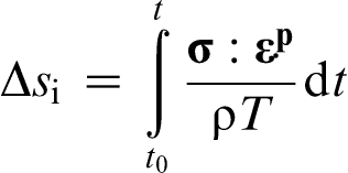
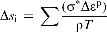
The process related to fatigue must involve permanent degradation due to irreversible processes that lead to failure. Naderi et al., 1 Amiri and Modares 31 and Liakat and Khonsari 32 performed several fatigue tests that show the cumulative entropy generation of specimens is constant at the time of failure and independent of load, geometry and frequency. The original idea of this theory, which was initially proposed by Basaran and Yan, is the following: entropy being the amount of energy lost and no more available in a system, one can assume that this thermodynamic quantity is related to the fatigue evolution of the specimen.2,8
In order to derive a physical fatigue evolution model, we will first present the laws of thermodynamics, which constitute the foundations of this theory. The internal entropy generation of the system given by the thermodynamic laws will then be used to derive a damage evolution parameter that can be considered as a lifetime predictor. The model is finally applied to two cases: uniaxial cyclic loading and monotonic traction. For each case, the damage parameter is calculated using experimental data obtained in the laboratory on steel samples.
Thermodynamic laws
There are four laws of thermodynamics to describe how fundamental physical quantities behave under various circumstances. These laws define the evolution of thermodynamic systems. For the purpose of this work, we only consider the first two laws that essentially relate temperature, energy and entropy of a system. These laws must be applied at a local scale to be combined with statistical mechanics. 2
Energy conservation
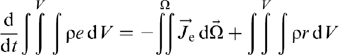
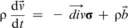
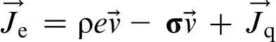
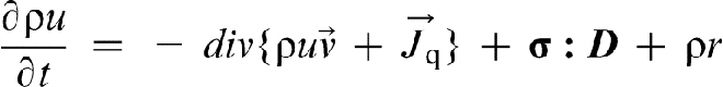
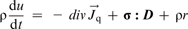
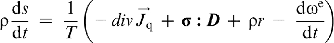
The first law of thermodynamics expresses the change of the total energy of a system as
Definition of variables used
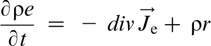
This law simply states that the variation of total energy of the system is due to internal heat source r and energy flux  across the surface boundary.
2
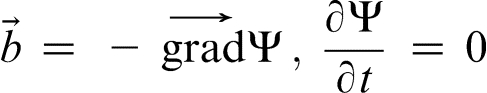
The negative sign of the energy flux is justified by the fact that the normal to the surface is outwards. Therefore, a negative energy flux is a positive external input of energy to the system. Taken at the local scale, this law becomes
across the surface boundary.
2
The negative sign of the energy flux is justified by the fact that the normal to the surface is outwards. Therefore, a negative energy flux is a positive external input of energy to the system. Taken at the local scale, this law becomes
 ) and total energy flux (
 )
)
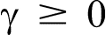
Clausius–Duheim inequity
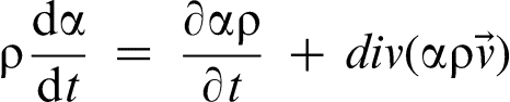
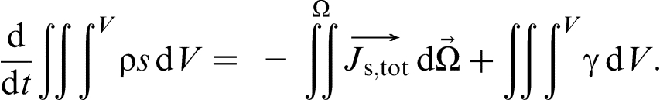
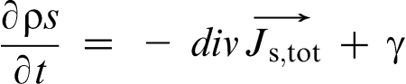
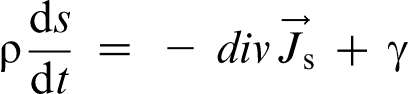
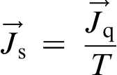
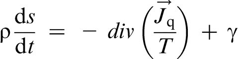
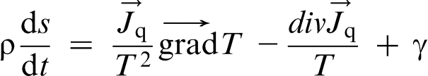
The second law of thermodynamics, also called Clausius–Duheim inequity, states that the internal entropy production is a positive quantity. Before writing that inequity, we will first express the entropy production. As for energy, the change in total entropy of the system is due to internal entropy source and total entropy flux across the surface boundary Ω:
 as the sum of entropy flux
  and a convective term
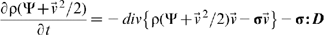
  and with the help of equation (10), equation (13) can be transformed into
 any vector
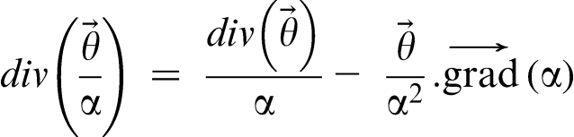
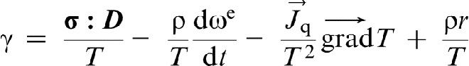
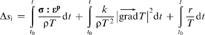
 . The internal entropy generation is then
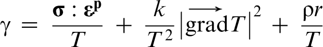
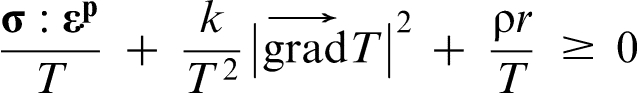
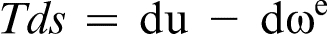
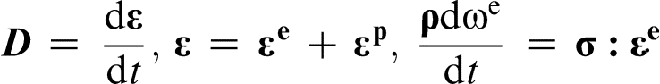
Entropy production represents the effects of irreversible processes in the system. In fact, the first term, the plastic work contains the effects of mechanical loading. The second terms takes into account the thermal loading, while the last term represents any other type of loading acting on the specimen.
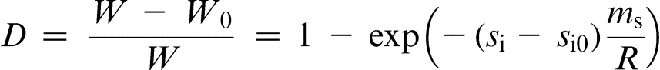
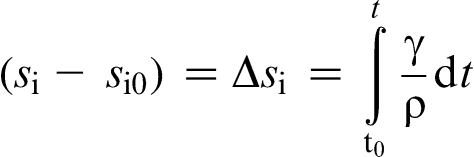
Damage evolution parameter
The internal entropy generation derived previously is a way to put the effects of irreversible processes undergone by the specimen. Now we are going to normalize this quantity to find a damage evolution parameter for mechanical fatigue process. This damage parameter will be equal to 0 at the initial state of life of the specimen, and it will progressively increase when the specimen is loaded to reach the value of 1 when failure occurs. This damage parameter will be derived via statistical mechanics.
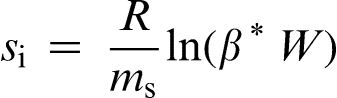
In 1898, Boltzmann
34
first used statistical mechanics to give a precise meaning of disorder in gas and established a connection between disorder and internal entropy for the whole system. The internal entropy is expressed as a function of W, the disorder function that represents the probability that the system will exist in the state relative to all the possible states it could be in
34
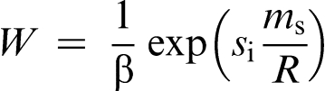
Verification of model
Now that the damage evolution parameter is defined, the model will be applied to two cases and validated through comparison with experimental data. First, a fully reversed uniaxial cyclic loading is considered, followed by a monotonic traction. The experiments were performed in the same conditions and on the similar specimen (Fig. 1) for the two cases.
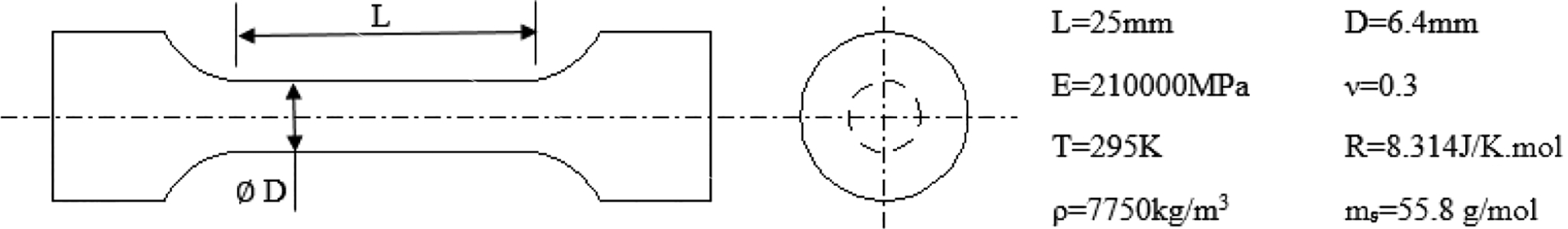
Specimen dimensions and properties
In order to evaluate the damage evolution parameter (which is the entropy production rate) in both cases, only the effects of mechanical load are taken in account. Considering equation (23), the second term that represents the thermal effect vanishes if we assume that heat generated during cycling loading is insignificant and the temperature of the specimen remains constant. The last term is not considered because the specimen is only subjected to mechanical loading, tension–compression. Furthermore, because the load is uniaxial, the problem is reduced to one direction, and the plastic work is the product of applied stress and induced plastic strain. The internal entropy generation is then reduced to
Tension–compression cyclic loading
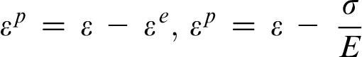
The experiment consists of a displacement controlled test conducted in an Material Testing System (MTS) material characterization unit, which applies uniaxial tension and compression in repeated and fully reversed cycles to a sample. The experimental data obtained from the digital output consist of forces (F) and displacements (u). The displacement's range is [ − 1;1 mm], which corresponds to a 4 maximum strain in the sample. The rate of loading is 0·5 hertz. Here, failure occurs after 80 cycles. Since we assume small strain in the model, plastic strain is calculated as follows
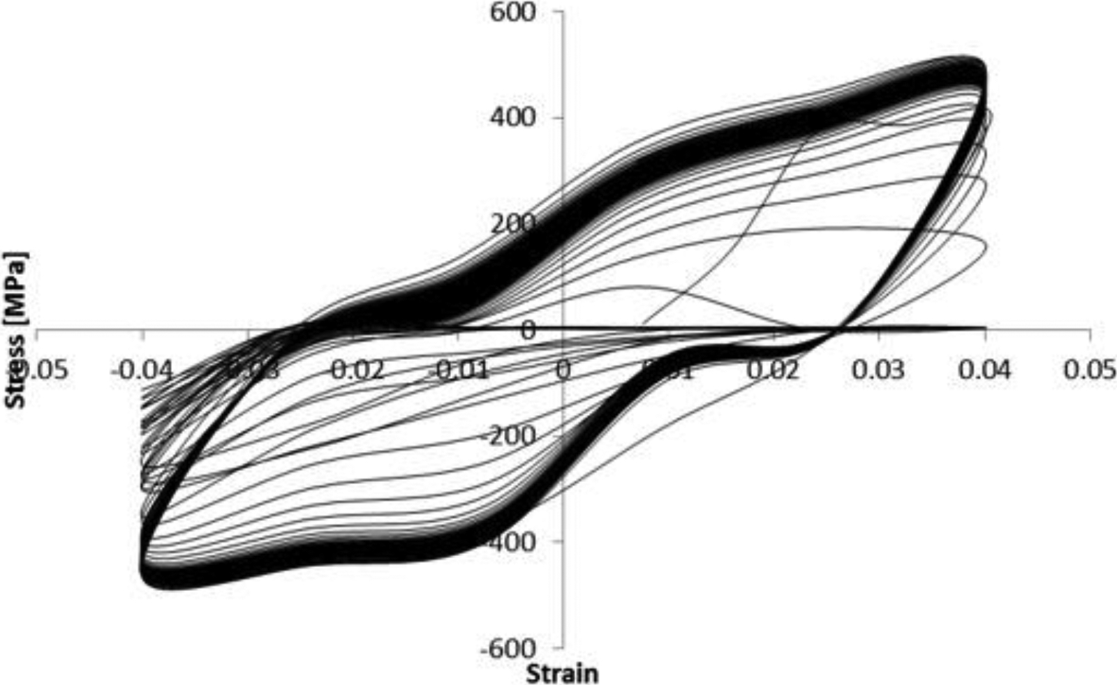
Stress–strain diagram of cyclic loading
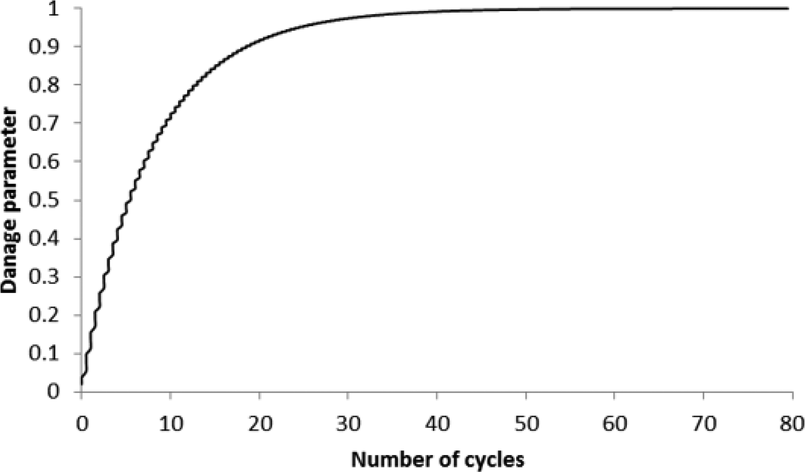
Damage parameter evolution for cyclic loading
Monotonic loading test
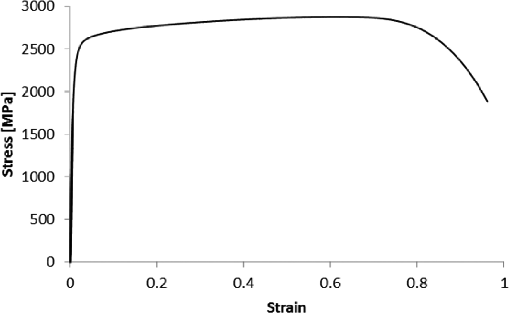
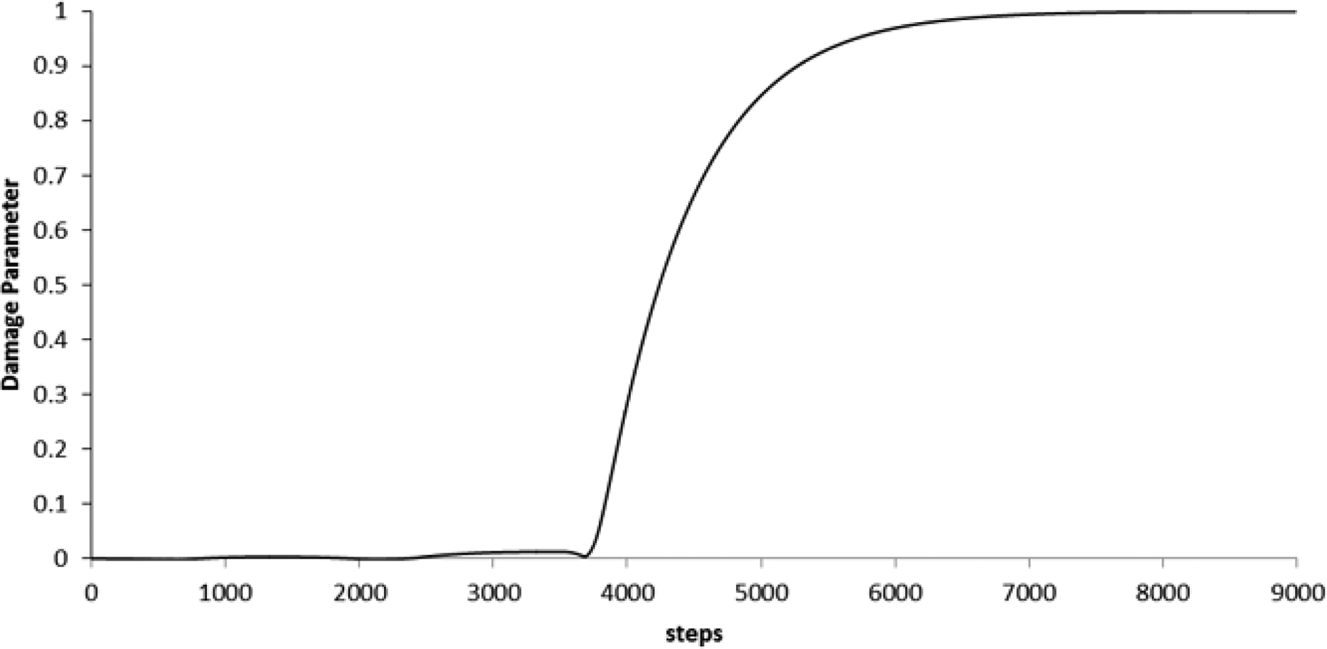
For this case, the sample is identical to the one used for the cyclic loading. The only difference is that this time it is continuously loaded until failure occurs. The loading is a uniaxial tension, and the experimental data is obtained in a similar fashion and treated in the same way as before. Figure 4 shows the stress–strain diagram obtained from experimental results of monotonic tension test performed on the specimen. Figure 5 presents the evolution of the damage parameter for the specimen. As expected, the initial damage is null, and the damage increases with the number of cycles and tends to 1 when the specimen breaks. But here, we can see that the damage parameter remains very small for a while before it starts to increase. This domain corresponds to the elastic range of the material. In fact, because we assumed that only plastic deformation could cause permanent degradation in the material, there is no entropy generated in the elastic range according to equation (24). Therefore, this model cannot be used in case of high cycle fatigue. Because in that case, failure occurs under elastic deformation only.
Stress–strain diagram of cyclic loading
Damage parameter evolution for cyclic loading
For the case of high cycle fatigue under elastic deformation in equation (16), irreversible entropy generation due to elastic work must be calculated.
Conclusions
A thermodynamic fatigue model using entropy generation as a damage metric has been proposed and validated by cyclic loading and monotonic loading. The internal entropy generation was calculated through the laws of thermodynamics and statistical mechanics. A component of a structure or even a whole structure can be considered a thermodynamic system. The damage evolution parameter D proposed represents the probability of failure of the considered component.
The model is adaptable to any type of loading undergone by the specimen (mechanical, thermal, electrical, chemical, etc.). It was shown that the model is suitable for a lifetime of components subjected to monotonic or cyclic loading. However, some assumptions that are valid most of the time were made to simplify the model. The model might need some improvement for some applications. Especially, it is assumed that elastic deformation cannot cause failure, which is not true. But compared to those of plastic deformation, the effects of elastic deformation are negligible and can be assumed to be null. In order to simulate high cycle fatigue due to elastic deformation, irreversible entropy generation due to elastic work must be calculated.
For practical use, the damage evolution parameter derived here must be multiplied by a safety coefficient. In fact, components must be checked and replaced long before their catastrophic failure. The safety coefficient may vary with the application. For instance, aircraft design and bicycle design do not require the same level of factor of safety.