
Abstract
This study mainly evaluates the elastic modulus of 316 stainless steel lattice structures fabricated via binder jetting process. In this present research, both solid and lattice samples are designed and fabricated by binder jetting process for two different types of mechanical tests. Besides experimental study, a numerical model based on energy approach has been proposed to predict the effective elastic modulus of fabricated lattice samples. By comparing the calculated results of the proposed numerical model with the experimental results, the established model is proved to be validated. This numerical model can be used to determine the parameters of lattice structures fabricated by binder jetting process for desired mechanical properties. At the end, both advantages and disadvantages of the lattice structures fabricated by binder jetting process are analysed. Based on this analysis, the potential application and future research work are pointed out.
Introduction
Cellular structure is a unique classification of the structure that is made up of an interconnected network of solid struts or plates that form the edge and faces of cells. 1 This kind of structure is common in nature, such as wood, animal bone and coral, which are able to bear a long term static or cyclical load. These natural cellular structures have been used by humans for centuries. Recently, some manmade cellular structures have been designed and fabricated for their multifunctionalities such as weight reduction, energy absorption, heat transfer, thermal protection and insulation.1–5
According to the geometrical configuration, cellular structures can be classified into many different types, such as foam, honeycomb and lattice structures. Among these different types of cellular structure, the lattice structure, which is a space truss structure composed of struts, nodes and other microelements with certain repeated arrangement in three-dimensional (3D) space, is the most attractive type of their inherent advantages. First, compared to those disordered cellular foam structures, only a small portion of lattice structures is needed to determine its properties for the high degree of order. Thus, this type of structure enables designers much more freedom to realise their design goals. Besides that, lattice structures can also be designed to be a stretching dominated structure for load bearing with high stiffness as well as a bending dominated structure for compliant mechanism with a large deformation. Because of the reasons mentioned above, lattice structures have high potential in a wide range of applications, such as automobile, aerospace, and medical devices and implants. However, the high manufacturing complexity is the biggest barrier for the wide application of lattice structures. Compared to those stochastic cellular foam structures, conventional fabrication processes of lattice structures, such as sheet metal forming, investment casting and metal wire bonding, are time and cost consuming. Moreover, because of manufacturing limitation, only the lattice structures with simple external geometry can be fabricated, which severely restricts the design freedom to achieve advanced functionalities.
Additive manufacturing (AM) is a material joining process whereby a product can be directly fabricated from its 3D model. 6 This innovative manufacturing technology enables the fabrication of parts with any shape, and thus has been used to fabricate the parts with both complex internal lattice and external geometry. Even though AM is a powerful manufacturing method with many unique capabilities, the qualification of additively manufactured parts is still one of the most serious hurdles for the wide adoption of this technology. To overcome this difficulty, significant research work has been done to improve the quality of parts fabricated by different types of AM processes. For example, some simulation and computational models have been proposed for different AM technologies such as fused deposition modelling7–9 and powder bed fusion10–12 to predict the quality factors of fabricated parts. Besides those simulation models, some research work has been done specifically focusing on the quality of lattice structures fabricated by different types of AM techniques. In the past few years, several different types of AM processes, such as electron beam melting (EBM), 13 selective laser melting (SLM), 14 direct laser metal sintering (DLMS) 15 and 3D printing (3DP), 16 have been employed to build metal lattice structure. These AM fabrication processes can be divided into two categories according to their fabrication principles. The first type is a powder bed fusion process where thermal energy is used to fuse the selective regions of a powder bed. EBM, SLS and DLMS belong to this type. The second type is a binder jetting process. In the binder jetting fabrication process, binder is used to temporarily connect powders in selective region, and then some post-process methods, such as sintering or infiltration, will be used to build a firm connection between metal powders. Compared to binder jetting process, powder bed fusion techniques enable the fabrication of fully dense metal parts (even >99.9) without the need for post-processes. 17 However, binder jetting technologies can fabricate more complex lattice structure with much faster speed and cheaper cost. 18
In order to fully understand the mechanical properties of metal lattice structures fabricated by AM process, several research has been done to establish the relationship between mechanical properties of metal lattice and its fabrication process. Heinl et al. 13 fabricate the lattice structure of Ti–6Al–4V for bone implant by EBM technique. Through relevant mechanical tests, it shows that the mechanical properties of fabricated structures are similar to those of human bone, which can avoid stress shielding effects after implantation. SLM technique has been used by McKown and et al. 14 to fabricate a range of stainless steel 316L lattice structures with two different types of unit cell topology. Both quasi-static and blast loading are used to study the lattice collapse behaviour and associated failure mechanism. More recently, several research has evaluated lattice structures fabricated by DLMS technique for two different materials: 316L stainless steel 19 and AlSi10Mg. 15 As to the binder jetting process, two-dimensional lattice structures for tensile testing have been fabricated by Galeta et al. 16 A series of experiments have been done to investigate the relationship between fabrication orientation and its mechanical properties. In general, most existing research works focus on the lattice structures fabricated by powder bed fusion processes. Only limited research has been done on the lattice fabricated by binder jetting processes.
To fill the current research gap, this paper mainly concentrates on the mechanical properties of lattice structures fabricated by binder jetting technique. In this present research, both compression and three-point bending tests have been conducted to study the elastic modulus of lattice structures made of 316 stainless steel, which is commonly used in the industry and biomedical applications. In addition to experimental research, a numerical model is also proposed predicting the effective elastic modulus of fabricated lattice structures based on mechanical properties of solid samples fabricated by binder jetting process. This numerical model can be used to determine parameters of lattice structures fabricated by binder jetting process for desired mechanical properties.
In order to achieve the goals mentioned above, the overall structure of this paper is organised as follows. In the ‘Experimental’ section, the detailed procedures of experiments are discussed. In the ‘Numerical model’ section, the numerical model that is used to predict the elastic modulus of lattice structures fabricated by binder jetting process is proposed. Then, the results of experiments and numerical model will be given in the ‘Results’ section. A discussion on both experimental data and calculated results is made in the ‘Discussion’ section. Finally, this paper is wrapped up with conclusions and future research directions.
Experimental
Material
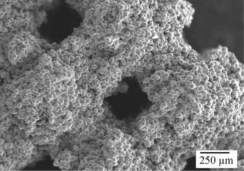
In this present research, lattice structures are made of 316 stainless steel powder with average particle size of  μm, which was gas atomised and produced by ExOne Company. The scanning electron microscopy (SEM) image of the stainless steel is given in Fig. 1. It is seen that the powders have a narrow particle size distribution and a nearly spherical shape. The chemical composition of used metal powder is provided in Table 1.
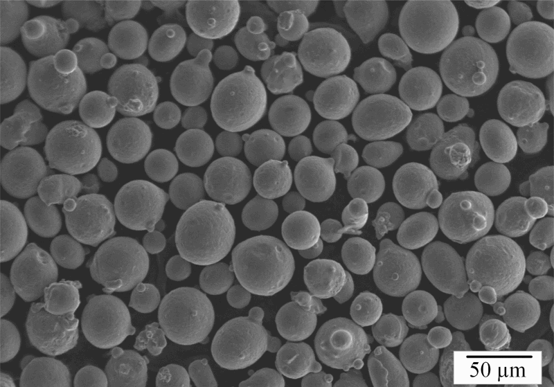
SEM image of 316 stainless steel powder
Chemical analysis of used 316 stainless steel powder/wt-

Design of testing parts
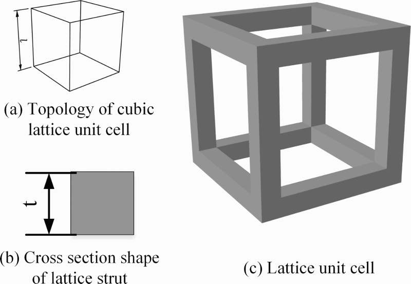
Lattice structures with cubic topology shown in Fig. 2 are used for this research. The length of cubic unit cell is called as the size of unit cell denoted by l (shown in Fig. 2a). The shape of each lattice strut's cross-section area is square (shown in Fig. 2b). The length of the square is referred as the strut's thickness, which can be denoted by t. These two independent parameters, unit cell size and strut's thickness, can be used to identify the geometrical shape of the lattice unit cell. Based on these two parameters, the relative density ρ* of designed lattice structure can be expressed as:
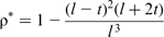
Cubic lattice unit cell
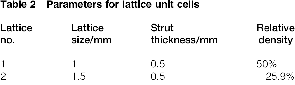
Parameters for lattice unit cells
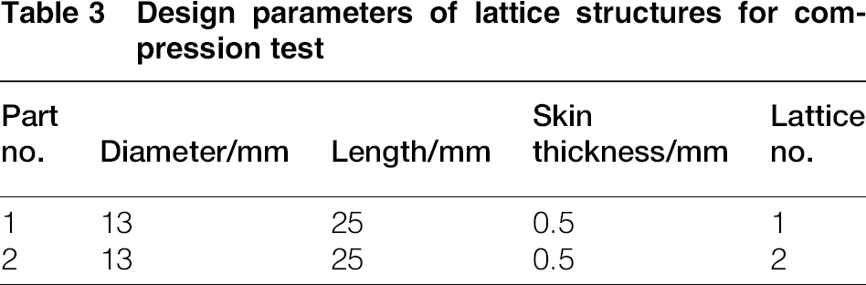
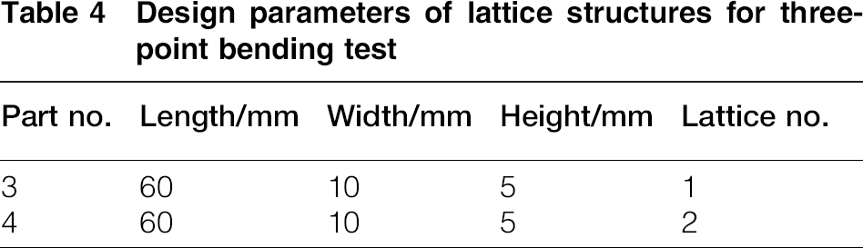
Lattice structures with two different external geometries are designed for compression and three-point bending tests respectively. For a compression test, cylinder lattice structures (shown in Fig. 3) with two thin skins are designed. The top and bottom skins are designed to guarantee the whole lattice structures under a uniform force during a compression test. Geometrical parameters of cylinder lattice samples for compression tests are shown in Table 3. For three-point bending test, a slender lattice bar with rectangular cross-section is designed, which is illustrated in Fig. 4. Geometrical parameters of designed lattice bars are given in Table 4.
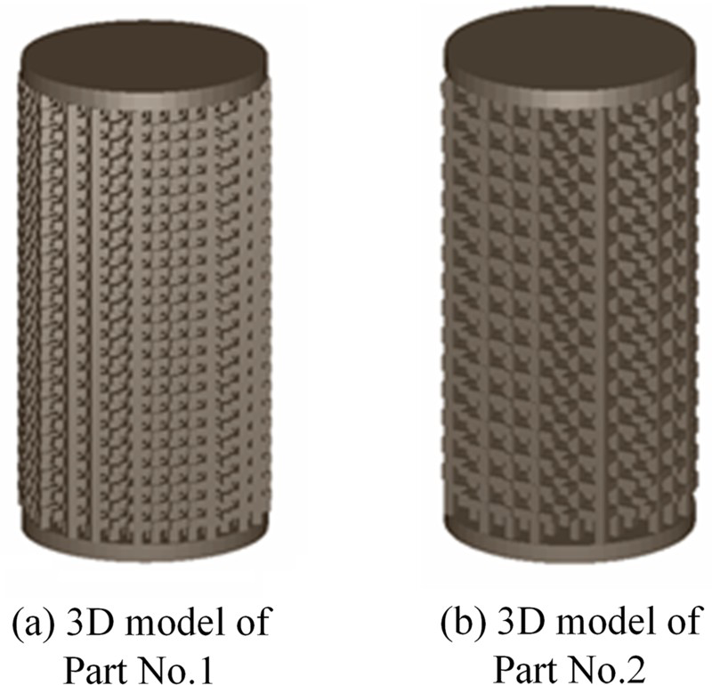
3D model of lattice cylinder for compression test
Design parameters of lattice structures for compression test
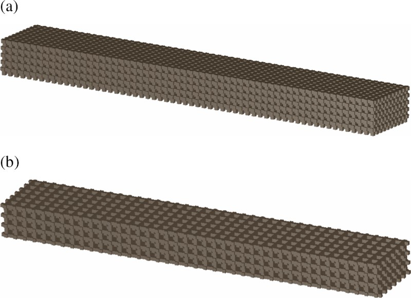
a 3D model of part no.3
Design parameters of lattice structures for three-point bending test
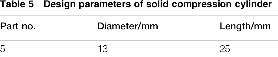
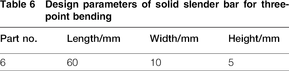
Besides these samples with lattice structures, two test parts (shown in Fig. 5) with regular solid material are also designed for compression and three-point bending test respectively. These solid testing samples are used to obtain the mechanical properties of solid stainless steel part fabricated by binder jetting process. The mechanical properties of solid samples will be used in the numerical model described in the next section to predict the effective elastic modulus of fabricated lattice structures. The geometrical parameters of these two designed samples are shown in Tables 5 and 6 respectively.
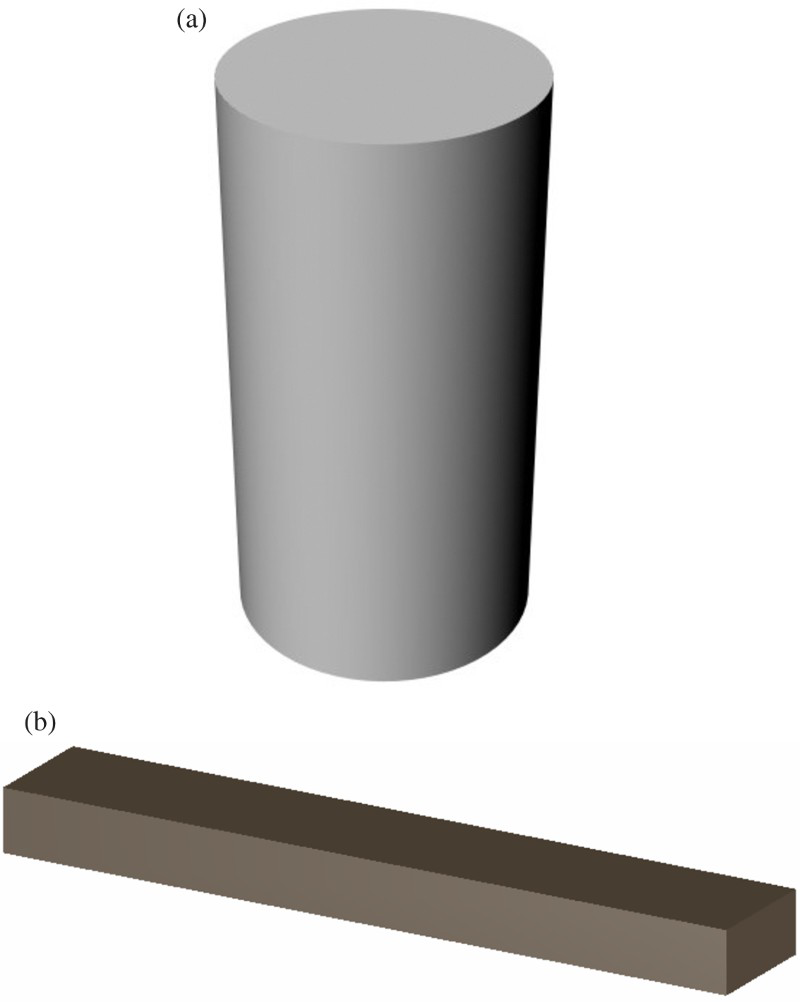
a 3D model of part no.5
Design parameters of solid compression cylinder
Design parameters of solid slender bar for three-point bending
Binder jetting fabrication process
Binder jetting process, one of AM processes, is originally developed at MIT in the 1990s. 20 The fabrication process of binder jetting technology can be divided into the following steps: printing, curing, depowdering and post-processes. The core step of the binder jetting process, which is different from other AM technologies, is the printing process. Figure 6 shows a schematic view of the printing process of binder jetting. The printing system consists of a printing bed, a feeding bed, a roller, a drying unit and a print head. The whole printing process works as follows: the print head first start to jet binder onto loose powders according to layer profile (shown in Fig. 6a). When one layer is finished, step motor system places the layer under an electrical infrared heater to remove excessive binder. The next step is shown in Fig. 6b; the printing system lowers printing bed one layer thickness and feed bed rises. Then, the roller evenly spreads a new layer of powder over the printed layer. This process is repeated layer by layer until a part is fully built.
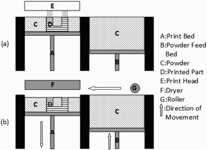
Printing principle of binder jetting process: a printing; b drying and spreading
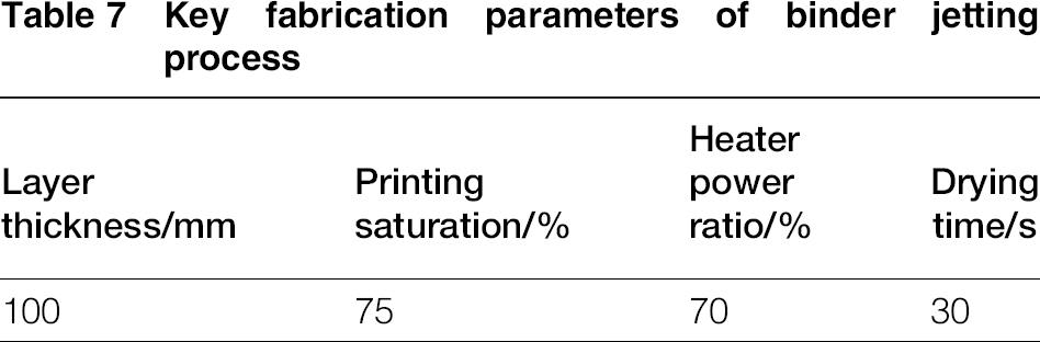
In this present research, the binder jetting manufacturing process is carried out on an ExOne M-Lab 21 3DP machine. To minimise the number of printed layers, the printing orientation is set to be perpendicular to the axial of designed cylinders and slender bars, which is shown in Fig. 7. In order to achieve the qualified quality of printed samples, four key fabrication parameters of binder jetting process are selected according to the previous research 22 for optimal geometrical quality, which is shown in Table 7. The detailed explanation of each fabrication parameter shown in Table 7 has been discussed by Chen and Zhao. 22 Thus, it will not be discussed in detail here.
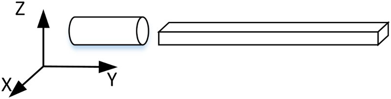
Printing orientation
Key fabrication parameters of binder jetting process
After printing process, a constant temperature drying oven (model: ExOne RCO-1) is used for curing process. Then, compressed air is applied to remove powders from printed structure. To further increase the mechanical properties of printed structures, the programmable sintering furnace (model: RF-D 9499200) is used for post-processes. During this process, the printed part is sintered without infiltration to obtain the structure with pure stainless steel. The recommended sintering curve from ExOne Company is used and shown in Fig. 8. Argon gas is used as protection gas during the entire sintering process.
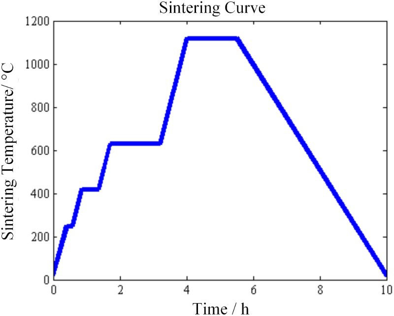
Sintering curve
Measurements
In this present research, two different mechanical testing machines are used for the compression test and three-point bending test respectively. For the compression tests, BOSE 3510 mechanical tester 23 equipped with 7.5 kN load cell is used to conduct the standard compression test on both lattice and solid samples fabricated by the binder jetting process. The speed of loading is set with a constant of 0.01 mm s−1 for all the compression tests. The stress–strain curves and elastic modulus of designed structures are obtained through the compression test. For three-point bending test, MACH-1 tester 24 equipped with 1 kN load cell is used. In the three-point bending test, the fabricated specimen is placed on two supports that are 38 mm apart, and the actuator applies a displacement in the exact middle of the two supports. The principle of three-point bending test is shown in Fig. 9. The speed of loading is set at a constant of 0.02 mm s−1 for all three-point bending test. Besides test machines, the Hitachi SU3500 SEM is used to take images of micro- and mesostructures of fabricated parts, and the Mastercraft digital caliper is used to measure the geometrical dimension of fabricated test samples.
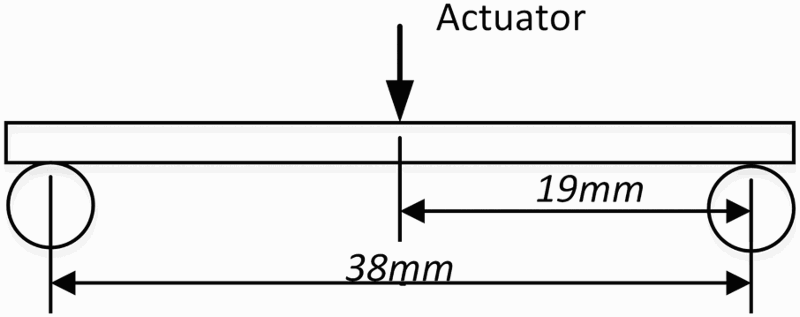
Principle of three-point bending test
Numerical model
In this section, a numerical model of the fabricated lattice structure is proposed. This model is established based on multiscale mechanics to calculate the effective elastic modulus of lattice structure fabricated by the binder jetting process. In this model, representative volume elements (RVEs) for designed lattice structures are built first. Then, the energy approach is applied to calculate the effective elastic modulus of lattice structures with respect to their RVEs.
RVE for lattice structures
In order to calculate the effective properties of solid parts fabricated by binder jetting process, the RVE needs to be established first. An RVE is a volume of material whose effective behaviour is able to represent the material as a whole. 25 Thus, the RVE must contain large enough volume in order to capture the essence of the microstructure from a statistical standpoint.
As mentioned at the beginning of this paper, lattice structures are composed of unit cells periodically distributed in the 3D Euclidean space. Thus, the RVE of given lattice structures should at least contain one unit cell. Moreover, in order to reduce the boundary effects during the numerical calculation, the more unit cells included in given RVE, the better. However, it should also be noted that the increasing number of unit cells will also significantly increase the computational load. To keep balance between them, the RVE that contains 27 unit cells is used in the proposed numerical model. Two RVEs for two different designed lattice samples are shown in Fig. 10.
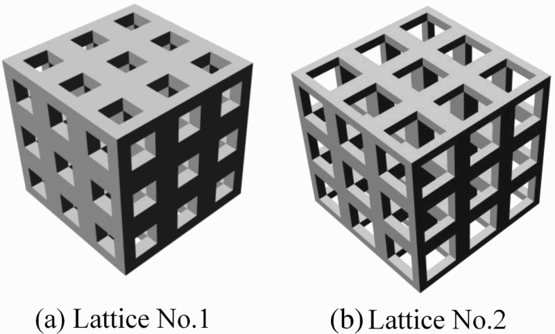
RVE of lattice structures
Energy approach
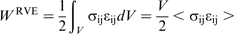
The effective elastic properties are determined by equating the elastic strain energy of the heterogeneous RVE to the elastic energy of effective homogenous material, which can be expressed as:

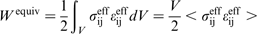
As to W
equiv
, it can be expressed as:
 and
and  are the effective stress and strain tensor. Under the Hill condition,
26
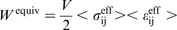
the volume average of the product of stress and strain is equal to the product of the volume average of stress and the volume average of strain. Thus, equation (4) can be rewritten into:
are the effective stress and strain tensor. Under the Hill condition,
26
the volume average of the product of stress and strain is equal to the product of the volume average of stress and the volume average of strain. Thus, equation (4) can be rewritten into:
 is the effective stiffness tensor of an RVE. Generally, there are three types of boundary condition that can be applied to calculate the effective properties of the given RVE. They are uniform displacement boundary condition, uniform traction boundary condition and mixed boundary condition. The calculated results from different boundary condition are supposed to be consistent with each other. Thus, the uniform displacement boundary condition is used in this present research to calculate the effective properties of RVE. Under uniform boundary condition, the displacement of the point on the boundary can be expressed as:

 is a constant tensor that represents a uniform strain. According to the average strain theorem, the volume average strain of RVE under this boundary condition should be equal to the applied uniform strain, which can be expressed as:

 for uniform boundary condition, the effective stiffness tensor
  can be solved by the combination of equations (2) and (9). Based on the relationship between elastic modulus and stiffness tensor, the effective elastic modulus of the RVE can be calculated.
Results
Fabricated parts
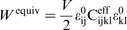
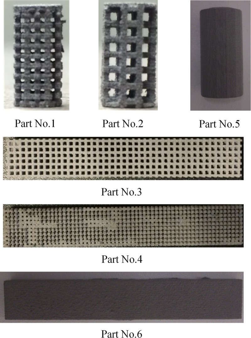
The designed parts are fabricated by the binder jetting process described in the ‘Experimental’ section. The results are shown in Fig. 11. For each design sample, five parts are fabricated. The SEM image of lattice structures for part no. 1 is shown in Fig. 12. It is clear that the thickness of fabricated lattice struts is approximately equal to 0.5 mm, which accords with the design parameters.
Fabricated parts for different designs
SEM images of fabricated lattice
It is clear from Fig. 12 that the metal powders are not fully merged during the sintering state. Thus, fabricated parts are not in the full density even for solid design. The mass of fabricated solid part is measured by the scale. Based on mass and part's dimensions, the density of fabricated solid part is calculated and the average density is only 4.1 g mm− 3, while the density of metal powder is 7.9 g mm− 3.
Compression test results
The compression tests have been done for both lattice structures and solid cylinder. The load–displacement data are recorded for each specimen, and the curve is generated. The example is shown in Fig. 13.
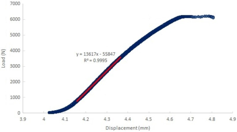
Load–displacement curve of part no. 1 under compression test
Linearly fitting is applicable to obtain the slope of the linear section of the load–displacement curve. The slope represents the stiffness of the sample, which is 13 617 N mm− 1. The elastic modulus is calculated from equation (10).
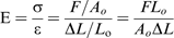
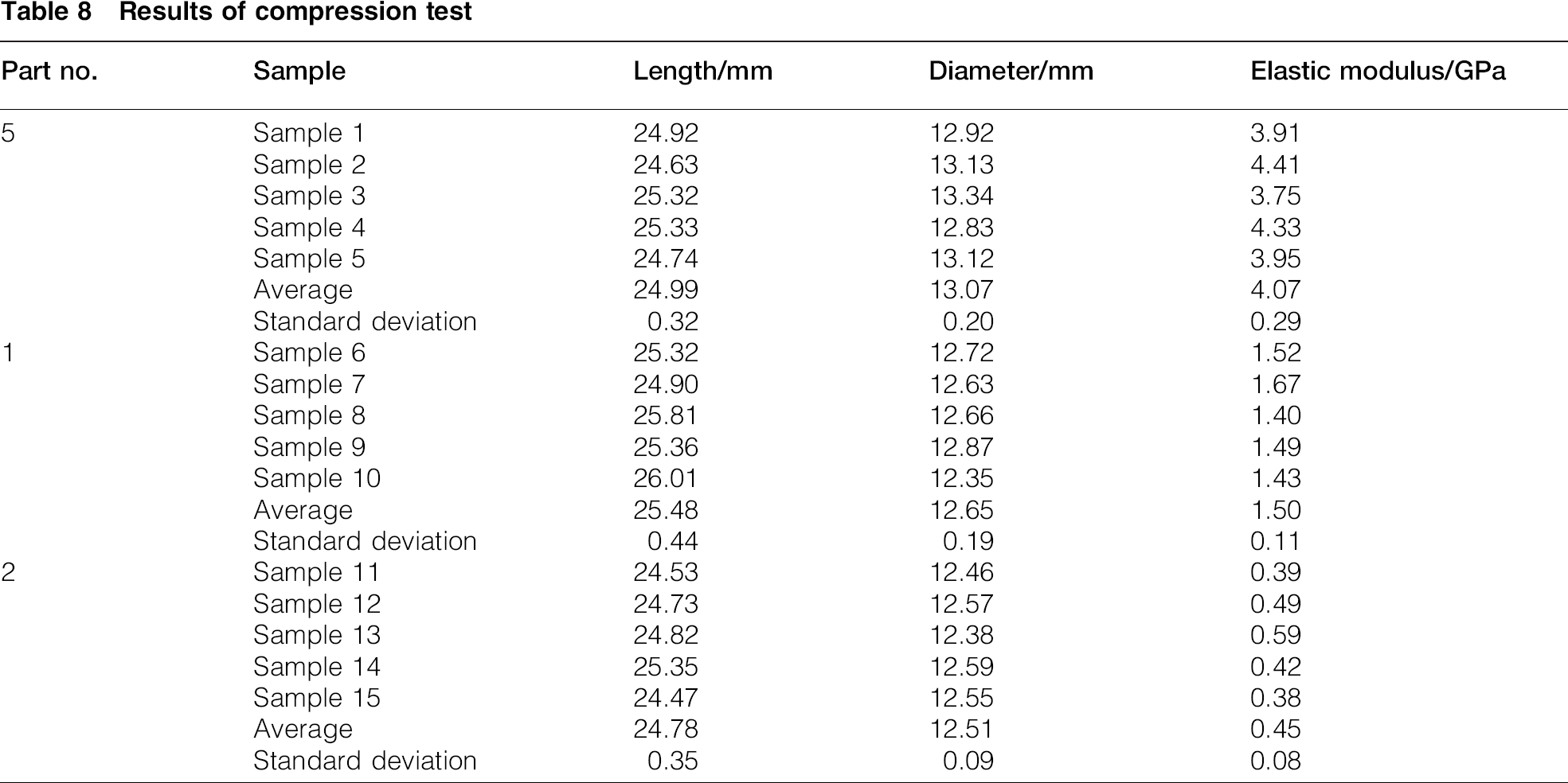
In equation (10), E represents the elastic modulus, σ is the compression stress, ε is the compression strain, F represents the load applied on the sample, L0 represents the original length of the sample, A0 represents the original cross-sectional area through which the load is applied, ΔL is the amount by which the length of the sample changes, and F/ΔL is the stiffness of the sample and can be represented by the slope rate of the load–displacement curve. The standard test sample is designed to be 25 mm in length and 13 mm in diameter. However, due to the possible manufacturing error, physical dimension measurements are conducted on each testing sample. Since the stiffness is related to the structure besides the material, it is not within the scope of this study. The elastic modulus of each sample is calculated from equation (10), and the average elastic modulus of each type of structure is the arithmetic mean of the five samples. Meanwhile, the standard deviation of elastic modulus for each type of design is also calculated. These results are shown in Table 8.
Results of compression test
Three-point bending result
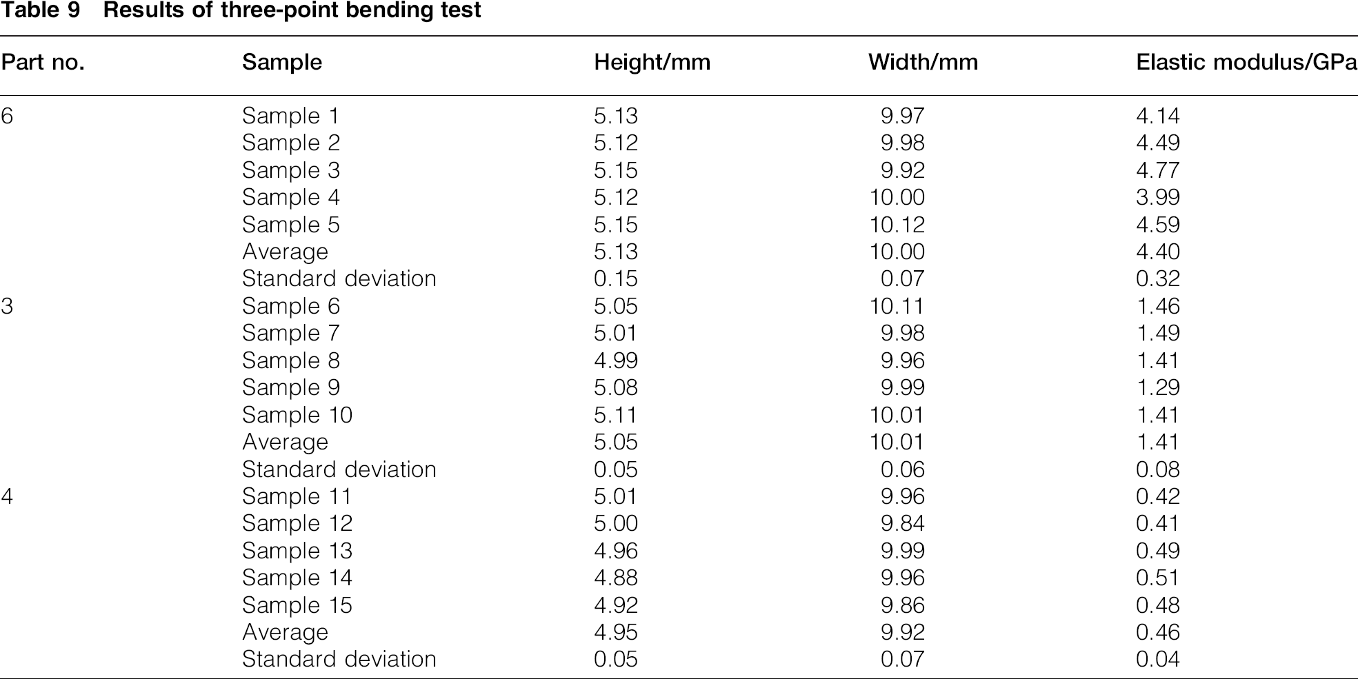
The elastic modulus is calculated for three-point bending test by the equation:

Results of three-point bending test
Numerical calculation results
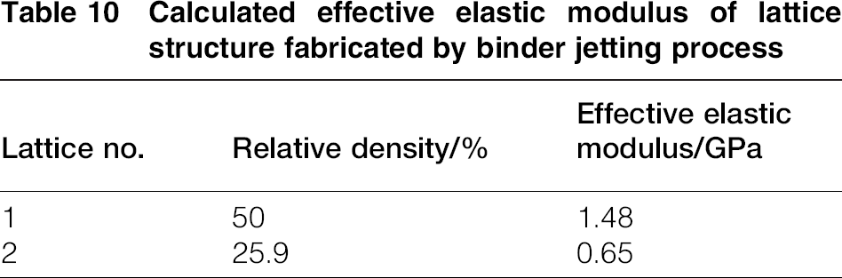
Since the cubic lattice is orthotropic with cubic symmetry, only one elastic modulus is needed to be calculated. The effective elastic moduli along three different symmetrical axes are equal to each other. Based on the experimental results of the compression test for solid samples and the numerical model described in the ‘Numerical model’ section, the effective elastic moduli of two different lattice samples are calculated and shown in Table 10.
Calculated effective elastic modulus of lattice structure fabricated by binder jetting process
Discussion
A comparison between the elastic modulus of standard 316 stainless steel and experimental results is shown in Fig. 14. It is clear that the elastic modulus obtained from compression and three-point bending tests correlates well with each other. Moreover, the elastic modulus measured from three-point bending test is slightly higher than that obtained from compression tests. However, compared to the elastic modulus of standard stainless steel, the measured elastic moduli from two different testing methods are both much smaller. One possible reason for this phenomenon is the high porosity of fabricated solid parts. The density of fabricated solid parts is only 4.1 g mm− 3 and ∼51 of original stainless steel powder. Another possible reason accounting for the weakness of fabricated solid parts is the poor connection between metal powders, which can be recognised from the SEM images of fabricated solid parts. These poor connections are mainly due to the short sintering time for the purpose of minimising sintering shrinkage. Thus, in the future fabrication process, a balance should be made between the parts’ shrinkage rate and its sintering time, which are directly related to mechanical properties of fabricated parts.
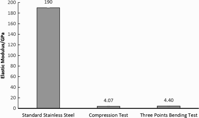
Elastic modulus of solid parts fabricated by binder jetting process
The calculated elastic moduli for different design configuration are compared with the experimental results and shown in Fig. 15. From this figure, it is clear that the mechanical properties of fabricated lattice structure are stable regardless of mechanical test methods. Moreover, the calculated results of the numerical model are consistent with the experimental results, which verify the validity of proposed numerical model for designed lattice structures.
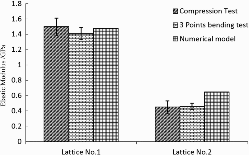
Elastic modulus of designed lattice structures
Compared with those lattice fabricated by SLM technique reported in the literature, 19 it is clear that the lattice structure fabricated by binder jetting process is less stiff with a smaller elastic modulus. This is mainly due to the relative low density of solid samples and partially sintered metal powders. It should be noted that the SLM can achieve a relative density nearly greater than 99, while the fabricated solid design samples in this present research by binder jetting process only have a relative density ∼50. Thus, lattice structures fabricated by binder jetting process are not suitable for those applications with critical stiffness requirements. However, due to its low relative density and porous struts, this type of structure is a potential candidate for tissue scaffolds, which require the micropores for nutrient diffusion.
Conclusion and future research
In the present paper, the mechanical properties of stainless steel lattice structures fabricated by the binder jetting process are studied. Compression and three-point bending tests have been designed and conducted to obtain the elastic modulus of fabricated parts. Five different types of test parts are designed. In these designed parts, the cubic lattice structure with two different geometrical configurations is used. Besides experimental study of mechanical properties of fabricated lattice structures, a numerical model based on energy approach is proposed. In this numerical model, the RVEs of lattice structures are firstly generated according to their unit cell. Then, the energy approach is applied to calculate the effective elastic modulus of the designed structure based on the assumption that the strain energy of real RVE structure is equal to the strain energy of equivalent homogenous material. The experimental result shows that the elastic moduli of fabricated parts are stable with a small standard deviation. Moreover, the elastic modulus of fabricated solid part is much smaller than that of standard stainless steel. The feasible reasons for this phenomenon are analysed. In addition, the comparison between experimental results and numerical modelling results is made. The consistency of the results between experiments and numerical model for both two types of lattice verifies the validity of numerical model proposed for lattice structures. Thus, this numerical model can be used by designers to determine the suitable geometric parameters of lattice structures fabricated by binder jetting process for desired material properties.
To summarise the research results from both experimental research and numerical analysis, it is clear that the elastic modulus of lattice structures fabricated by binder jetting process is smaller than that of those structures fabricated by other AM processes such as SLS and DMLS. To further improve its mechanical process, sintering process needed to be optimised and other post-processing processes such as infiltration needed to be done. Thus, in the future, more research should be done to optimise the post-process of binder jetting fabrication. However, compared to those lattice structures fabricated by SLS and DMLS, the porous lattice struts make this type of lattice structure become a suitable candidate for tissue scaffolds. Those micropores on lattice struts enhance the nutrient diffusion during the cell culture process. Thus, more research works also needs to be done to investigate the effects of those micropores on the cell culturing.
Footnotes
Acknowledgements
This research work is supported by Biomomentum Inc. and National Science and Engineering Research Council Engage [Grant no. 462653-14] and China Scholarship Council [Grant no. 201306020032].