
Abstract
Carbon fibre reinforced magnesium matrix (Cf/Mg) composite components were made by liquid–solid extrusion process following vacuum infiltration technique. The effect of varying fabrication parameters (extrusion temperature, infiltration pressure and filling pressure) on the forming quality of Cf/Mg components was investigated. The experimental results showed that the extrusion temperature and the infiltration pressure played important roles, and the filling pressure played a secondary role. The components can be obtained at an extrusion temperature of 590°C, an infiltration pressure of 20 MPa and a filling pressure of 0.2 MPa. The ultimate tensile strength of the Cf/Mg composite components was 290 MPa, which was increased by 81% compared with that of casting AZ91D.
Introduction
The needs to reduce weight have been proposed in aerospace and automobile industries. In this regard, owing to the poor strength and Young's modulus of magnesium alloys at room temperature, to realise the application potential of magnesium alloys, further improvement in the mechanical properties could be achieved by reinforcement.1–3 Carbon fibre reinforced magnesium matrix composites (Cf/Mg) exhibited many advantages over the magnesium alloys including high specific strength and specific stiffness, low thermal expansion coefficient and satisfying secondary processing performance, which resulted in good application prospects in aerospace system.4–6 Then, the Cf/Mg composites have become an alternative material for the aluminium–magnesium alloy due to the need for lightweight materials.7,8 Over the last several decades, there has been a considerable increment in the use of Cf/Mg composites. A P100/AZ91C composite rigid pipe was prepared by vacuum casting and used in the frame structure. The National Aeronautics and Space Administration reported series research of the Cf/Mg composites and disclosed a zero expansion honeycomb support component using Cf/Mg composites for space mirror. 9 Therefore, magnesium matrix composite components have wide potential applications in aerospace engineering, such as rocket engine shells, satellite antennas and space station installation plates.9,10 The previous fabrication methods of metal matrix composites were difficult to be applied to the Cf/Mg components because of high chemical activity and low oxidation resistance of magnesium alloy and poor wettability between carbon fibre and the molten magnesium alloy. 11 The infiltration quality mainly relied on the perfect wettability between reinforcement and matrix alloy in pressureless infiltration. In gas infiltration technique, composites were fabricated by forcing liquid alloy to penetrate into preform under gas pressure in a sealed container, which required high equipment safety and brought high equipment cost. 12 In squeeze casting, molten alloy can be poured into the mould directly, but the magnesium melt is easy to be oxidised. 5
Liquid–solid extrusion process following vacuum infiltration (LSEVI) technique was a new technique for fabrication of metal matrix composites, which integrated preform heating, magnesium alloy melting, vacuum pouring and pressure infiltration in a whole system and significantly improved the material utilisation.13–16 However, the fabrication of large scale and thin wall Cf/Mg components bring great challenge to the uniform infiltration along both vertical and horizontal direction, and the key is the reasonable selection of fabrication parameters.
A thorough understanding of the fabrication parameters was essential for fabricating high quality Cf/Mg composite components. In the present paper, the LSEVI technique was applied to fabricate thin wall Cf/Mg composite components. Reasonable fabrication parameters were obtained by investigating the effects of the different fabrication parameters on the surface quality, the microstructure, the mechanical properties and the internal quality of the Cf/Mg composite component. The comparison of ultimate tensile strength (UTS) for Cf/Mg composite components was also performed to verify the rationality of the fabrication parameters.
Materials and methods
The shape and dimension of the large scale and thin wall component to fabricate is shown in Fig. 1, which is characterised by the large size of the mould cavity and variable cross-section shape in one body.
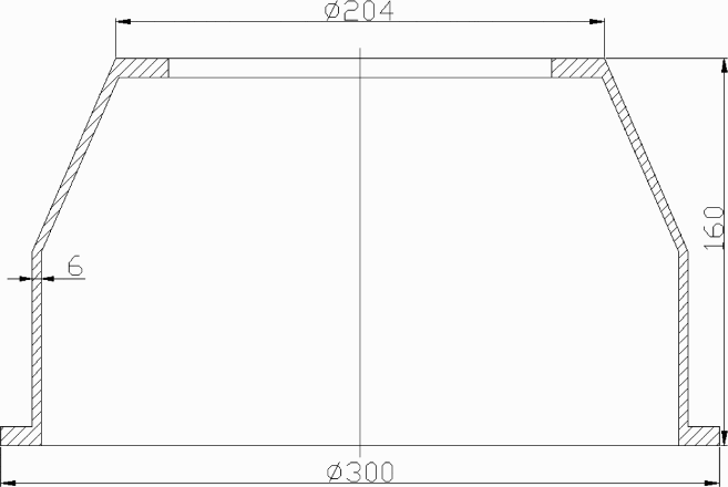
Drawing of Cf/Mg composite component
The component had a relatively uniform wall thickness of 6 mm, so the heat loss of the molten magnesium during infiltration will be great. 4
Materials
The AZ91D magnesium alloy (Mg–9Al–1Zn–0.2Mn, wt-%) was used as the matrix alloy due to its excellent castability and mechanical properties and produced by Magontec Xian Co., Ltd.
Toray T700 carbon fibre was selected as the reinforcement, which has a diameter of 7 μm, a density of 1.78 g cm− 3 and a tensile strength of 3.9 GPa. Fibre placement, filament winding, stitching in the thickness direction and weaving were carried out to achieve the variable cross-section of the preform with 0°/90° arrangement and a thickness of 6 mm, as shown in Fig. 2.
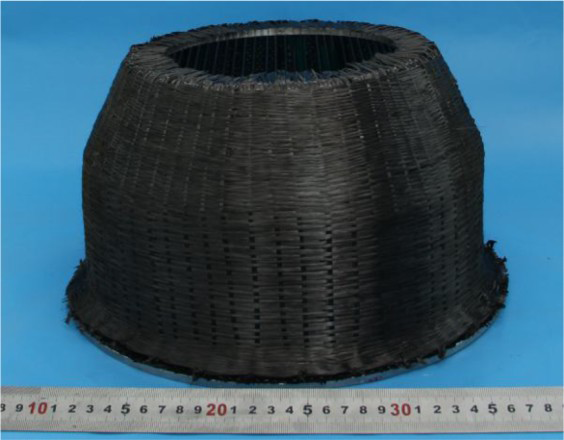
Carbon fibre preform
To improve the wettability between carbon fibre and magnesium alloy, chemical vapour deposition method was applied to deposit pyrolytic carbon coating on the surface of carbon fibre under the following process parameters: deposition temperature, 1000–1050°C; flowrate of CH4, 0.6–0.8 m3 h− 1; and deposition time, 3–4 h.17,18
Methods
The Cf/Mg composite components were prepared by LSEVI technique, and the schematic experiment is shown in Fig. 3. First, the preform was placed into the mould cavity and preheated to 600°C, which was 5°C above the liquids temperature of AZ91D (595°C) for avoiding premature solidification of the flow front of liquid metal in the preform. Meanwhile, about 4.5–5.5 kg AZ91D magnesium alloy was melted in a mild steel crucible at 730°C, at which liquid magnesium alloy has perfect filling ability. The top of crucible and moulds were covered with insulation board. Second, the mould cavity was evacuated to 0.02 MPa using a vacuum pump, and the liquid magnesium alloy was injected into the mould cavity under a preset filling pressure with the assistance of gas pressure. Third, the liquid metal was forced to infiltrate into the carbon fibre preform under a certain pressure from punch. 14 Finally, after infiltration, to further eliminate residual holes among adjacent fibre bundles, a higher force was applied to the surface of the liquid melt when mould temperature was cooled to 580–600°C.
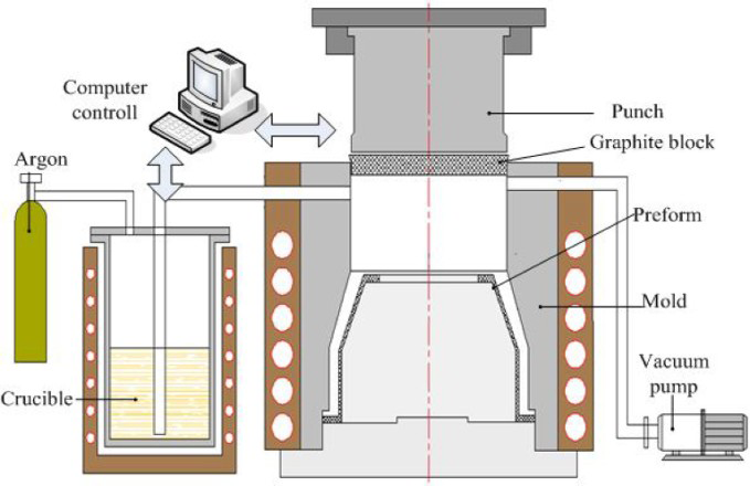
Experimental schematic of LSEVI system
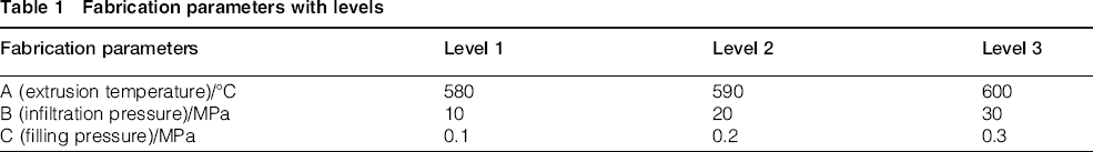
For the magnesium matrix composites, the infiltration pressure should be properly controlled. That is because a high infiltration force is beneficial to improve the infiltration quality, and it was selected as about 10–30 MPa in the present experiment. Filling pressure is the force for driving the molten magnesium into the cavity. It is hard to realise saturated infiltration under low filling pressure; as a result, the surface integrity of the component will not be guaranteed, so the filling pressure was selected as 0.1–0.3 MPa in the experiment. The composite components were obtained after removing the mould materials and redundant alloy. The fabrication parameters, namely, extrusion temperature, infiltration pressure and filling pressure each at three levels, were considered in the present work, and the details are presented in Table 1 (regardless of the interaction among them).
Fabrication parameters with levels
The fabricating quality of Cf/Mg composite components was investigated, and the comprehensive evaluation score was evaluated in terms of the morphology completeness, the microstructure uniformity, the surface quality after machining and the leakage level of the molten magnesium based our previous experimental results, as shown in Table 2. 19
Rank of components
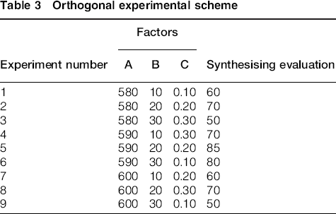
In the present study, a three-levels orthogonal array L9 (34) with nine experiments was selected in the preliminary experiment. Tables 3 and 4 showed the orthogonal experiment scheme and results.
Orthogonal experimental scheme
Orthogonal experimental result
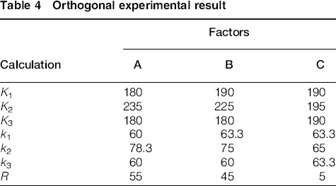
The fabrication quality was optimised by orthogonal designs and range analysis. ki was the sum of the corresponding experimental results when the column number is i (i = 1, 2 and 3). ki was the arithmetic mean of the corresponding experimental results when the column level factors were i

In formula (1), ‘s’ was the number of occurrences of each level in every column. ‘R’ was the range, and the computation formula is as follows

In the experiments, the score was raised with the quality improved, so the maximum level of ‘K’ was chosen as the corresponding factor.
The column of factor A

The column of factor B

The column of factor C

Experiment 5 produces the best score in Table 2, and the combination level was A2B2C2, in which fabrication parameters were the extrusion temperature is 590°C, infiltration pressure is 20 MPa and filling pressure is 0.2 MPa. The level of the range analysis R showed that the order of all factors in the experiment process is as follows: extrusion temperature, infiltration pressure and filling pressure. 20 The extrusion temperature obviously affected the fabricating quality of the structure, the next was the infiltration pressure and the last one was the filling pressure.
Test
A TESCAN VEGA II scanning electron microscope was used to observe the microstructure and tensile fracture surface of the Cf/Mg composite components. Element chemistry configuration of components was analysed by scanning electron microscopy with energy spectrum analysis (EDS). Mechanical properties tests were conducted on a CMT5304-30KN universal electronic tensile testing machine. Three specimens were cut along the longitudinal direction of the Cf/Mg composite component. The dimension of the tensile specimens was 2 × 10 × 75 mm according to the dimension of the component. Sartorius-CP225D analytical balance with precision of 1 × 10− 4 g was used to test the density based on the Archimedes's principle, which means that the weight reduction of the object in the fluid by the buoyancy effect is equal to the volume of the same weight of the fluid.
Results and discussion
Effect of extrusion temperature on surface quality
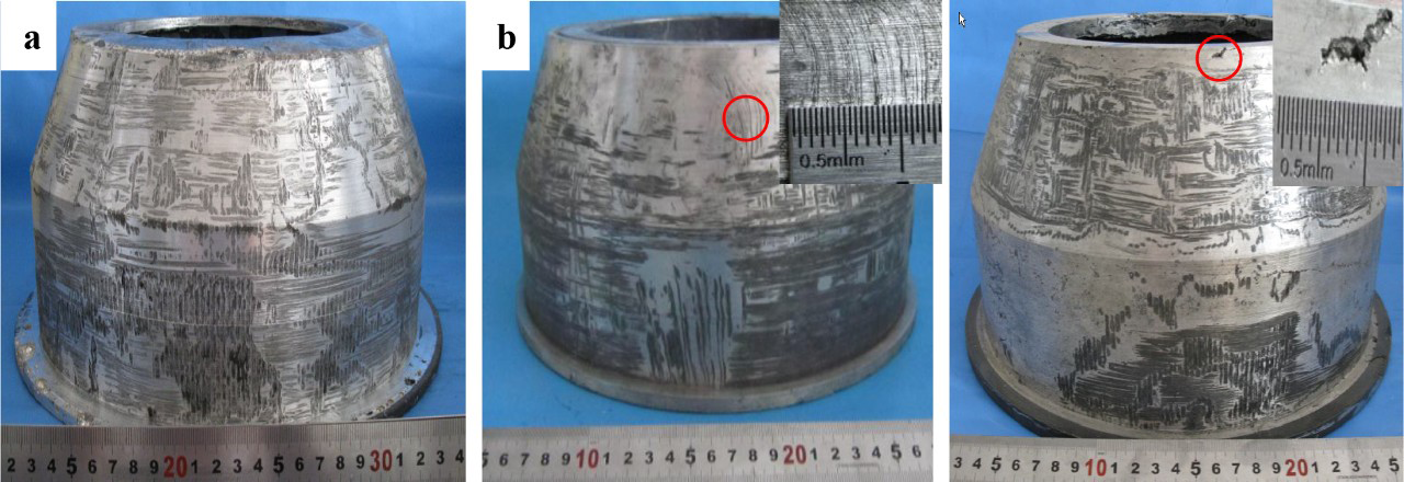
In order to investigate the effect of extrusion temperature on the surface quality, the experiments were carried out using the following parameters: extrusion temperatures were selected at 580, 590 and 600°C, with infiltration pressure of 20 MPa and filling pressure of 0.2 MPa. Figure 4a–c shows the Cf/Mg composite components fabricated at the extrusion temperature 580, 590 and 600°C respectively.
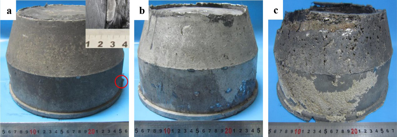
a 580°C; b 590°C; c 600°
Figure 4a shows that the filling and infiltration quality were not satisfied due to high solid fraction of molten AZ91D when the extrusion temperature was 580°C. The appearance of the Cf/Mg composite component was acceptable, but the uneven phenomenon was observed at the bottom position. Figure 4b shows the Cf/Mg composite component with a high quality surface, complete filling and clear framework. The seal between the punch and the container was achieved when the extrusion temperature was 590°C, which makes the molten AZ91D infiltrate into the fibre bundle under a rated pressure. Figure 4c shows a lot of macroscopic defects within and outside the Cf/Mg composite component. There was a leakage of molten magnesium alloy from the space between the graphite blocks and container under the extrusion load because the AZ91D alloy was at full liquid state and had a good filling performance at 600°C, which caused the feeding magnesium alloy to be insufficient. 21
Effect of infiltration pressure on microstructure and its mechanical properties
In order to investigate the effect of infiltration pressure on the microstructure, the experiments were carried out with the following parameters: extrusion temperature, 590°C; filling pressure, 0.2MPa; and infiltration pressure, 10, 20 or 30 MPa. Figure 5 shows the microstructure of the components produced under the infiltration pressures of 10, 20 and 30 MPa respectively.
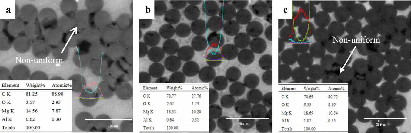
a 10 MPa; b 20 MPa; c 30 MPa
The infiltration can be defined as ‘non-uniform’ in Fig. 5a and c and ‘uniform’ in Fig. 5b. In the non-uniform infiltration, some molten magnesium was infiltrated into the carbon fibre bundle (Fig. 5a). It is difficult to fill tiny gaps among carbon fibres because the liquid magnesium alloy always has high priority to fill the larger pores of the preform. When the fibre preheating temperature is above the liquid temperature of magnesium alloy, the chilling effect of fibres on the molten magnesium alloy can be ignored, and the flow time of the molten magnesium in the preform will be enough long before solidification. Further filling can be achieved with higher infiltration pressure for a long holding time after the infiltration.22–24 Uniform distributions of fibres in the matrix can be achieved (see Fig. 5b). The microstructure observation indicates that the distribution of carbon fibre in the matrix was uniform with no defects, such as layering, inclusion and carbon fibre breakage. In Fig. 5c, the space among adjacent fibres in the fibre bundle is filled with magnesium alloy, but there exists local fibre agglomeration. The feeding of molten magnesium alloy is not enough due to leakage and burning. From the corresponding energy spectrum analysis, the good sealing state was maintained in the process when the infiltration pressure was 10 and 20 MPa because the corresponding oxygen atomic contents were 2.05 and 1.73% respectively. When the infiltration pressure was 30 MPa, the leakage and burning of molten magnesium happened due to the seal failure, so more oxygen appeared in the EDS test.
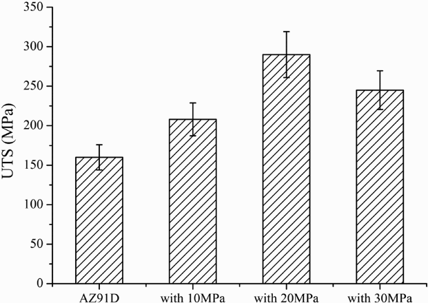
The average UTS of Cf/Mg composites fabricated at different infiltration pressures is shown in the Fig. 6. It was clear that the UTS of Cf/Mg composite were increased than that of AZ91D alloy. The UTS with uniform infiltration (20 MPa infiltration pressure) was increased by 81% than that of the casting AZ91D alloy (160 MPa). The Cf/Mg composites component showed superior mechanical properties due to the addition of carbon fibres.
Comparison of mechanical properties for composites and AZ91D alloy
Fracture morphologies (as shown in the Fig. 7) of Cf/Mg composites fabricated under different infiltration pressures can also be used to verify the importance of the uniform infiltration.
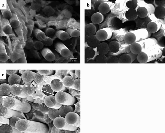
a 10 MPa; b 20 MPa; b 30 MPa
The load transfer requires a moderate bonding between carbon fibre and matrix. When the extrusions are 10 and 30 MPa respectively, the microstructures are not compact, and the bonding is discontinuous due to the voids. Then, the load is in a local sharing mode and cannot be transferred effectively from matrix to fibres, which results in poor performance in the tensile test.25,26 In Fig. 7b, obvious steps were observed in the fracture surface, which indicated that the bonding was moderate. In the tensile test, the cracks causing carbon fibre fracture would spread to the matrix, and the propagation path mainly depends on the interface bonding strength. When the interface bonding was moderate, microcracks can bypass the interface and make the Cf/Mg composites well withstand a high load. The failure mechanism of Cf/Mg composites with moderate bonding can be described as follows: cracks are generated from void in the magnesium alloy. The load is transmitted through the interface along the vertical direction of the tensile axial line. Some of the carbon fibres were broken, and other carbon fibres continue bearing the load until the composites fractures completely.27,28 The Cf/Mg composites in Fig. 7b have obvious uneven fracture; thus, the interface bonding is moderate, and the corresponding UTS is the highest.29,30
Effect of filling pressure on internal quality
In order to investigate the effect of filling pressure on the internal quality, the experiments were carried out under the following conditions: extrusion temperature, 590°C; infiltration pressure 20 MPa; and filling pressure, 0.1, 0.2 and 0.3 MPa respectively. Figure 8a–c shows Cf/Mg composite components under the filling pressure of 0.1, 0.2 and 0.3 MPa respectively.
a 0.1 MPa; b 0.2 MPa; c 0.3 MPa
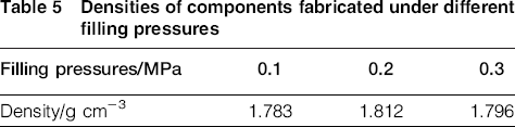
Figure 8a shows a Cf/Mg component with poor surface quality. It can be inferred that misrun and shrinkage cavity occurred when the filling pressure was 0.1 MPa. Figure 8b shows a complete surface with a few limited defects. The filling pattern of magnesium alloy melt was sequential when the filling pressure was 0.2 MPa, which was beneficial for obtaining relatively stable filling and good for reducing the shrinkage porosity. Figure 8c shows that the Cf/Mg composite component has been formed, but some holes remained on the machining surface. The molten magnesium flow presented as the reverse filling when the filling pressure was 0.3 MPa. 31 The densities of components fabricated under different filling pressures were also measured, and the results are shown in Table 5. It can be found that the component with the densest microstructure was obtained under the filling pressure of 0.2 MPa, and the densities of components were sensitive to the filling pressure.
Densities of components fabricated under different filling pressures
Conclusions
Experiments were conducted to analyse the effect of fabrication parameters on the Cf/Mg composite components. The involved process parameters include extrusion temperature, infiltration pressure and the filling pressure. From the analysis, the following conclusions can be drawn.
The large scale and thin wall Cf/Mg composite components can be fabricated by LSEVI technique with satisfactory internal and surface quality. The effect of the order of fabrication parameters on the components’ quality was the extrusion temperature, the infiltration pressure and the filling pressure. Under the optimised fabrication parameters of the extrusion temperature of 590°C, the infiltration pressure of 20 MPa and the filling pressure of 0.2 MPa, the Cf/Mg composite components presented good surface integrity and dense microstructure. The UTS of the Cf/Mg composites component was 290 MPa, which was increased by 81% compared with that of casting AZ91D. The tensile fracture surface indicated that the bonding between carbon fibres and magnesium alloy was moderate.
Footnotes
Acknowledgement
The present work was supported by the National Nature Science Foundation of China (grant nos. 51275417 and 51221001), the National High-Tech R&D Program of China (grant no. 2014AA8011004B) and the 111 Project (grant no. B08040).