
Abstract
Detailed studies were carried out to study the effect of air core formation in cyclones on separation of particles using statistical techniques. The design and operating variables of a 100 mm perspex hydrocyclone, both flat bottom and conical, were varied and their effect on different types of air core was studied. The results were analysed using analysis of variance. The % underflow split was the most important variable affecting the air core formation. Studies were also carried out with density tracers under different air core conditions. The studies showed that the lighter particles separated better in the absence of the air core. Particle separation tests were then carried out after suppressing the air core with a metal rod. The separation of lighter particles with specific gravity close to the separating fluid was improved when the air core was suppressed. Numerical simulation studies showed that a higher tangential velocity and a lower radial velocity is the reason for better separation efficiency in the absence of the air core.
Introduction
The cyclone is a simple device, which causes the centrifugal separation of materials in a fluid stream. Unlike the slow setting within a settling tank, the pump and cyclone separator system yields fast separation and utilises less space. Separations occur quickly because one g of gravitation force is replaced by many g's of centrifugal force. These materials may be particles of solid, bubbles of gas or immiscible liquids. In the case of two solids suspended in the feed liquid they may separate according to size, shape or density. The cyclone utilises the energy obtained from fluid pressure to create rotational fluid motion. This rotational motion causes the materials suspended in the fluid to separate from one another or from the fluid quickly due to the centrifugal force. The rotation is produced by the tangential or involuted introduction of fluid into the vessel.
Flow inside a cyclone
The flow pattern in the normal design of cyclone is a spiral within a spiral. Fluid on entry commences downward flow in the outer regions of the cyclone body. This, combined with the rotational motion, creates the outer spiral. The existence of a top central outlet and the inability under normal feed pressure and flowrate conditions for all of the fluid to leave at the cone apex outlet assists the inward migration of some of the fluid from the external downward moving mass. The amount of inward migration increases as the cone apex is neared. Rotation of the fluid creates a low pressure axial core which normally results in a free liquid surface. The core in a cyclone which directly communicates with the atmosphere at either one outlet becomes air filled. The surface of the air core will be found to be irregular due to the continuous disturbance from progressive waves.
The air core in a cyclone
Formation of the air core is considered to be an indication of vortex stability. It is essential that the feedrate and the pressure be sufficient to give this stability. It follows that for any cyclone there is a minimum flow rate and consequently a minimum pressure drop or feed pressure. The size and stability of the air core is believed to affect the metallurgical performance of the separator. In addition, models have been developed using advanced fluid dynamics simulations which can predict the formation, the size and shape of the air core. Steffens et al. (1993) developed a mathematical model of the flow within a simplified hydrocyclone using the Navier Stokes equations and also investigated the behaviour of the air core within a hydrocyclone and its effect on the flow splits to products. Davidson (1995) analysed air core diameter in a hydrocyclone using the physics of uniform density, and inviscid flow at each outlet, modified by an empirical factor to account for viscous effects. Dyakowski et al. (1995) developed a new method to predict the size of the air core within a hydrocyclone by calculating the internal pressure distribution.
In a cyclone, the pressure drop is known to affect the air core formation significantly. Noriler et al. (2004) claims that 80% of the pressure drop directly influences the tangential velocity peaks and that it is possible to change the velocity profiles in a cyclone by using the fluid dynamics behaviour of the swirling flow.
Objective of the study
A dense medium cyclone (DMC) is a special type of cyclone where the medium used is a dense medium like magnetite and is mainly used in coal washing. For hard-to-clean coal (±10% near gravity material) in the size range of 50–0·5 mm, DMCs are used. Indian coals with their high near gravity material are very difficult to wash. The main aim of the study was to modify the existing design of the cyclone to separate the near gravity material effectively. To start with, a simple Perspex cyclone with water as the medium was used for the study.
An effort has been made to study the effect of different operating and design variables on the formation of air core using statistical techniques. Artificially prepared particles of different specific gravity, some heavier and some lighter than water were introduced through water media and their separation studied. The better separation of the lighter particles with specific gravity closer to that of the fluid has been explained through single phase numerical simulation.
Experimentation
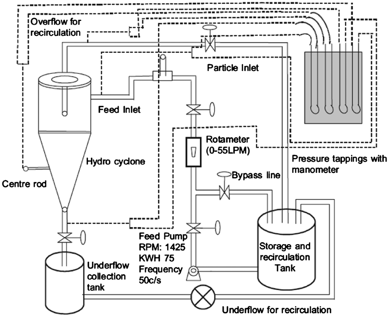
A 100 mm perspex cyclone was arranged in closed circuit with a water tank, a pump and a by-pass line as shown in Fig. 1. The by-pass valve in the line was used for adjusting the feed rate of water to the cyclone and the pressure at the feed inlet of the cyclone. The tests were carried out with both the flat bottom and conical design. A calibrated rotameter was fitted to the inlet line to measure the inlet flowrates. The liquid was injected tangentially by an inlet pipe fitted to the flat bottom portion of the hydrocyclone. The mercury manometers were provided to measure the pressure drop across the hydrocyclone. A high capacity tank was provided to collect the recycled liquid from the spigot and vortex finder (VF) and to recycle back to the inlet section of the hydrocyclone (Sripriya et al., 2007). The volumetric flowrate of feed liquid could be maintained by regulating the flow through the gate valves. The diameter of the spigot and the VF were kept constant. However, the VF and the spigot were fitted with valves so that the flow split could be adjusted. The tests were repeated three times and the average of three readings was noted to avoid inconsistency/error in readings.
Schematic of experimental set-up
To suppress the air core, the cyclone was modified. A metal rod 5 mm in diameter was grooved in through the conical body of the cyclone at a height of 39 mm from the cyclone roof. Figure 2 shows the design dimensions of the two cyclones along with the metal rod used for suppressing the air core.
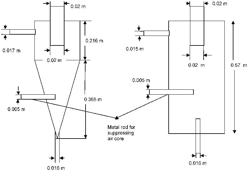
Schematic of conical and flat bottom cyclone with dimensions
Variables used for the tests
For the tests, different operating and design variables of the cyclone were considered.
Three different inlet types: the tangential inlet, off-tangential inlet and the involute inlet and two different cyclone designs, the conical and the flat bottom were used for the study. All the above variables were studied for both the flat bottom and conical cyclone. In all the cases, the experiments were done as per the mixed 2 and 3 level full factorial design. The data were assumed to be normally distributed. The results were analysed using analysis of variance (ANOVA). The purpose of ANOVA was to test for significant differences between means by comparing (i.e. analysing) variances. A statistical package STATISTICA was used for the analysis. Tests for the significance of the effects in the model were performed via the Wald statistic. The Wald statistic (Dobson, 1990) or the p statistic which is computed as the generalised inner product of the parameter estimates with the respective variance–covariance matrix, is an easily computed, efficient statistic for testing the significance of effects.
Test series 1
A variable % underflow split was defined which is
different types of air core:
Variables and levels used for ANOVA analysis in test series 1
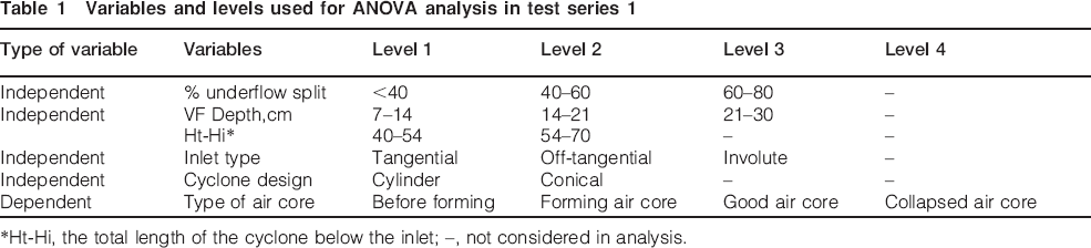
*Ht-Hi, the total length of the cyclone below the inlet; –, not considered in analysis.
The significant variables and interactions affecting the type of air core were studied. The effect of the independent variables on the dependent variable the type of air core was studied.
Test series 2
Provisions were made in the circuit for introducing particles into the cyclone. Instead of considering the VF depth, a dimensionless variable Hi/Ho was defined as the ratio of the height of the inlet to the VF depth. This along with the other variables, i.e. types of inlet, cyclone design were used in the study. The variables were varied to get the desired type of air core, i.e. before forming, forming, good and collapsed and the particle separation studies were carried out. For this, the same set-up as explained above was used. At a particular Hi/Ho, type of inlet and cyclone design, the flow was allowed to stabilise.
Density tracers of different specific gravity say 0·93(54 in number), 1·3(18 in number), 1·6 (18 in number) and 2 (18 in number) were introduced. Care was taken to have equal number of particles above and below the specific gravity of water. The particles coming out from the overflow and the spigot were collected and counted. This procedure was repeated at different levels of the variables and the results were again statistically analysed as explained above to determine the important variables affecting the separation of particles. The levels and the variables studied are given in Table 2.
Variables and levels used for experimentation in test series 2
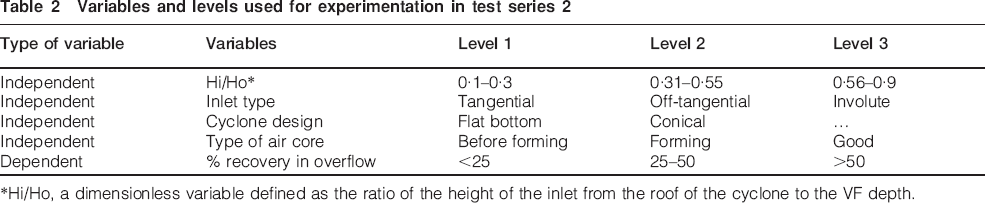
*Hi/Ho, a dimensionless variable defined as the ratio of the height of the inlet from the roof of the cyclone to the VF depth.
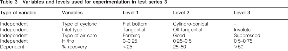
Test series 3
At a particular Hi/Ho, inlet type and cyclone design, the desired air core was obtained, in this case, forming/good or suppressed air core. The air core was suppressed using the procedure mentioned in the section on ‘Experimentation’. Under the conditions, the particle separation studies were again carried out. This procedure was repeated at different levels of design and operating variables (Table 3).
Variables and levels used for experimentation in test series 3
Numerical model
Introduction to FLUENT
FLUENT is a commercially available computational fluid dynamic (CFD) code developed by FLUENT, which utilises the finite volume formulation to carry out coupled or segregated calculations (with reference to the conservation of mass, momentum and energy equations). It is ideally suited for incompressible to mildly compressible flows.
To model the swirling turbulent flow in a cyclone separator, there are a number of turbulence models available in FLUENT. These range from the standard k-epsilon model to the more complicated Reynolds stress model. It has been shown by Boysan et al. (1992) that the standard k-epsilon model is inadequate to simulate flows with swirl because it leads to excessive turbulence viscosities and unrealistic tangential velocities. The accuracy of the numerical solution can be improved by using the Reynolds stress model, which forgoes the assumption of isotropic turbulence and solves a transport equation for each component of the Reynolds stress, but it has the disadvantage of being computationally expensive.
The most pragmatic option to accurately model the turbulent flow in a cyclone is the RNG based k-epsilon model. The RNG-based k-epsilon model was originally derived by Yakhot et al. (1986) from the instantaneous Navier–Stokes equations using a statistical technique called renormalisation group (RNG) methods. The analytical derivation results in a model with constants different from the standard k-epsilon and an additional term in the equation for e. The presence of this additional term improves the accuracy of the solution for rapidly strained flow found in a cyclone. Additionally, the effective viscosity in the RNG based k-epsilon model in Fluent is calculated from an equation includes the effect of rotation or swirl in the mean flow. Near the walls of the cyclone, enhanced wall treatment functions were used to describe the near wall behaviour. The enhanced wall functions were developed by smoothly blending an enhanced turbulent wall law with the laminar wall law. The approach allows the fully turbulent law to be easily modified and extended to take into account other effects such as pressure gradients or variable properties.
Discrete phase modelling
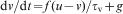
The particle loading in a cyclone separator is typically small (3–5%), and therefore, it can be safely assumed that the presence of the particles does not affect the flow field (one way coupling). The equation of motion for an individual
particle can be written as (Launder et al., 1974)
 is defined in terms of the particle density, particle diameter and the viscosity of the air as (Crowe et al., 1998)


 is the relative Reynolds number and CD is the drag coefficient. In FLUENT, the drag coefficient for spherical particles is calculated by using the correlations developed by Morsi et al. (1972). For non-spherical particles, the correlation was developed by Haider et al. (1989). The ordinary differential equation (2) was integrated along the trajectory of an individual particle. Collection efficiency statistics were obtained by releasing a specified number of monodispersed particles at the inlet of the cyclone and by monitoring the number escaping through the underflow. Collisions between particles and the walls of the cyclone were assumed to be perfectly elastic (coefficient of restitution is equal to 1).
Gambit, a preprocessor available in Fluent was used to create the geometry, mesh it and set the boundary condition. Velocity inlet was used as the inlet boundary condition and pressure outlet boundary condition was set at the two outlets.
Simulations were conducted using version 6.3.26 of the Fluent CFD software. The Quick scheme was used as the discretisation scheme for momentum, and for pressure–velocity coupling, the SIMPLE algorithm with a steady state solver was used. Water was used as the fluid with an inlet velocity of 41 lpm. Its density is 998·3 kg m−3 and viscosity 0·001 kg m−1 s−1. Grid independence studies showed that variation in % recovery was between 3–5% once the number of cells crossed 245 000. This was acceptable. Therefore, in all the cases the number of grids was restricted to 245 000.
Once the mass flux residuals reduced to 10×10−5, the simulations were assumed to be complete. Particles of different specific gravity 0·26, 0·8, 0·93, 1·03, 1·3 and 1·5, all of size 3 mm were then injected with inlet as the surface. The DPM model was used for particle injection. As many as 3000 particles were injected and the number of particles reporting from the two outlets was noted. Then the same formula as before was used to calculate the % recovery of particles in the overflow.
Horizontal line surfaces were created at different heights in the study the velocity and pressure profiles.
Results and Discussion
Experimental work
Test series 1
The ANOVA analysis of the tests is given in Table 4. Of the various variables studied, the % underflow split was found to be the most significant. None of the interactions were found to be significant. The % underflow split affects the pressure drop. As the % underflow split increases, the pressure drop increases. When the low pressure region in the hydrocyclone drops below the atmospheric pressure, air enters the cyclone (Nowakowski et al., 2004). Although the actual formation of the air core is not known, the prevalent thought is that the air enters from both outlets and eventually reaches a critical point, which combines the two air vortices (Cullivan et al., 2004). When the % underflow split increases to 75%, the air core collapses, causing an increase in the pressure drop to the maximum.
ANOVA table showing results of design of experiments (DOE) analysis for test series 1*
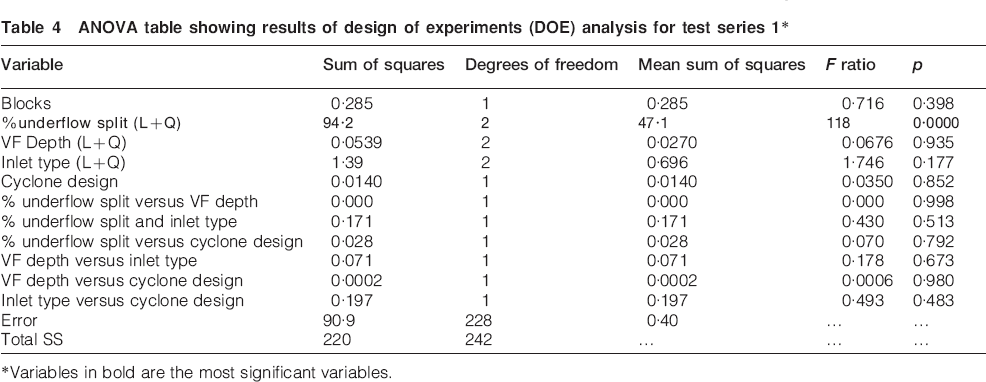
*Variables in bold are the most significant variables.
Another plot that was particularly useful for exploring the nature of interactions is the plot of marginal means. The plot clearly showed (Fig. 4) how the factor was related to the resulting type of air core. The plot of marginal means of the % underflow split against the type of air core showed that at <40% underflow split, the air core would be a forming air core; between 40 and 60% underflow split, it would be a good air core and between 60–80%, the air core would collapse.
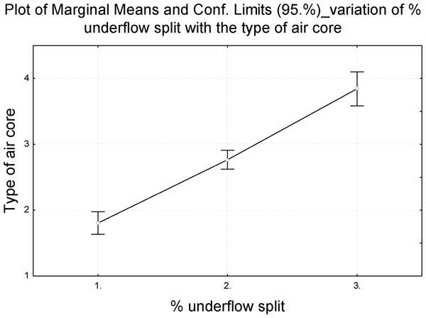
Plot of marginal means showing effect of % underflow split on type of aircore
Test series 2
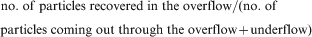
The results of the test work showed that the recovery of heavier particles was 100% in all the tests. This is because the particles being heavier than water were immediately thrown towards the wall as soon as they entered the cyclone and reported to the right stream. Variation was observed only in the recovery of lighter particles to the overflow. A dependent variable % recovery in overflow was defined which was
The ANOVA analysis (Table 5) showed that the most significant variable affecting the % recovery of lighter particles in the overflow were: the type of air core; the cyclone design; the interaction between cyclone design and the type of air core.
ANOVA table showing results of DOE analysis for test series 2*
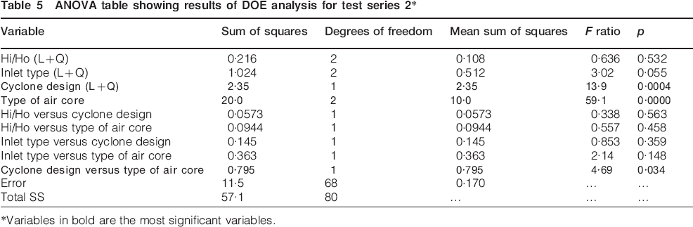
*Variables in bold are the most significant variables.
The recovery of lighter particles is the least when a stable air core is formed and is the best before the formation of the air core. The air in the air core generally has a tendency to move upwards, thereby creating an upward drag force on the liquid at the air liquid interface. This drag force caused the heavier particles to be dragged along with the lighter particles, thus resulting in misplacement. Also the air core due to is unsteady shape and size is associated with rocking and shaking inside the hydrocyclone, resulting in an unstable operation. Though maximum recovery of particles was observed before the formation of the air core, the condition caused jamming of the spigot. The heavier particles were found circulating near the spigot. The condition was similar to the roping condition in the cyclones, where the apex is overloaded. For free flow of the overflow and the underflow, it would be essential to operate at conditions where a stable air core forms; suppressing the air core would then remove the instabilities associated with the air core without hampering the operation of the cyclone (Luo et al., 1989).
The conical cyclone could separate particles with specific gravity close to that of the medium effectively, the effect being more pronounced in the absence of the air core.
Test series 3
Operation of the cyclone at the condition before the formation of the air core resulted in the jamming of the spigot. This was because of higher % of solids in the underflow, which caused the blocking of the spigot. An alternative option would be to operate the cyclone in flow regimes in which a good air core forms and then suppress it. A method was devised to suppress the air core in the cyclones the details of which is explained in the section on ‘Test series 3’. The rod was inserted to that extent till the air core disappeared. The statistical analysis of the results showed that the most important variables affecting separation of particles was the type of air core and the cyclone design. The maximum recovery of particles in the overflow was obtained when the air core was suppressed. The inserted rod eliminates the drag force that exists in the air liquid interface that is responsible for misplacement of particles.
The normal probability plot of residuals was used to determine if the residual values were normally distributed. The residuals closely followed the line indicating a normal distribution. Thus, it was concluded that the normality assumption was not violated in the data.
Fluent results
To understand the fluid flow in the cyclones, the conical cyclone with tangential inlet and a Hi/Ho of 0·58 was considered. The simulation was run for different target % underflow splits (25, 45 and 75%) in the manner discussed in the section on ‘Numerical model’ and the flow analysed. The underflow splits were changed to simulate the conditions of different types of air core.
Tangential velocity
Since the flow is strongly swirling tangential velocity is the most important one for the performance of a hydrocyclone in the three-dimensional velocities. The tangential velocity profile can be seen as two regions with an outer region of quasi-free vortex flow surrounding an inner region of quasi-forced vortex flow. This type of vortex is often referred to as a Rankine type vortex (Peng et al., 2002). The velocity profiles in both regions can be expressed with the equation

The tangential velocity plots projected to a horizontal plane at y = 0·1405 m at the VF tip is shown in Fig. 5. All curves have high velocities close to the cyclone wall, but they start to differ towards the centre. In the region closed to the wall, there appears to be no shear and the fluid behaves like a solid rotating body. The velocity decreases with decrease in radius. The tangential velocity reduces from a maximum at the wall to a point below the VF wall. This is because of the fluid entering upward through the VF. In the VF region, an outer region of free vortex followed by an inner region of forced vortex can be seen. This demonstrates two different zones of forced vortex flow.
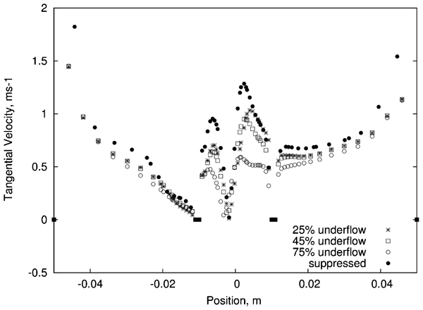
Tangential velocity plot at horizontal plane y = 0·1405 m at VF tip for conical design
Two observations could be made clearly from the plots:
first, the cyclone with the inserted rod and that with the 25% underflow split reached a higher maximal velocity than the others
second, the transition between free vortex and solid body rotation was much sharper in the two cyclones. On an average, the tangential velocity in the cyclone with the rod insertion is more by 10% and with the 25% underflow split is more by 5–6%.
The higher velocity is beneficial to the centrifugal settling of the treated particles towards the wall (Xu et al., 1990; Chu et al., 2004), and also helps in better redistribution of the internal energy (Sripriya, 2012). At the wall and at the centreline, the tangential velocity is zero.
Axial velocity
Figure 6a gives the axial velocity plot projected at a horizontal plane y = 0·1405 m at the VF tip. The plot shows a decrease in velocity at the VF wall, the decrease being maximum for the cyclone with inserted rod followed by 25% underflow split. The decrease of the axial velocity of fluid nearby the entrance of the vortex finder is beneficial to reducing the mixing of high density particles in the overflow product. Also in the region of the vortex finder, the high axial velocities help in carrying the lighter particles to the overflow product faster.
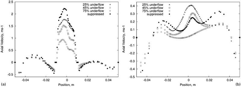
Axial velocity plot at a horizontal plane y = 0·1405 m at VF tip for conical design and b horizontal plane y = 0·07 m in cylindrical section for conical design
At y = 0·07 m (Fig. 6b), it can be seen that the cyclone with 25% underflow split has the highest upward axial velocity followed by 45% underflow split and then 75% underflow split. The rod inserted cyclone has the least axial velocity because of the external pressure force created due to the inserted rod.
Radial velocity
The radial velocity Ur is the smallest of the three components. Figure 7 shows the radial velocity plots of the different cyclones projected on horizontal planes at y = 0·07 m and y = −0·16 m respectively. The cyclone with the inserted rod and that with the 25% underflow split have smaller radial velocities than the other cyclone. The reduction in radial velocity is advantageous for separating lighter particles because the drag forces, acting towards the centre, are reduced.
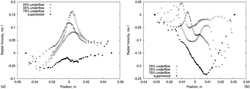
Radial velocity plot at a horizontal plane y = 0·07 m in cylindrical section for conical design and b horizontal plane y = −0·16 m in conical section for conical design
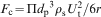
After investigating the tangential and radial velocities in the cyclones, some quantitative analyses on the separation in the cyclones become available. Let a particle with diameter d rotate at radius r. The particle will be subjected to three kinds of forces: an outward centrifugal force Fc, an inward drag force Fd and an inward floating force Fr, resulting from the radial pressure gradient. The three forces have the following forms respectively


Pressure contours
The pressure is an important parameter of hydrocyclone operation. The static pressure plots of the different cyclones projected at different horizontal planes, y = 0·1405 m, y = 0·07 m, y = −0·16 m are shown in Fig. 8a, b and c respectvely. High pressure drop will require a lot of energy to pump the fluid (Wanwilai et al., 2008) and hence higher operating cost. The cyclone with 75% underflow split had the highest pressure drop followed by that with 50% underflow split, 25% underflow split. The cyclone with the inserted rod had the lowest pressure drop.
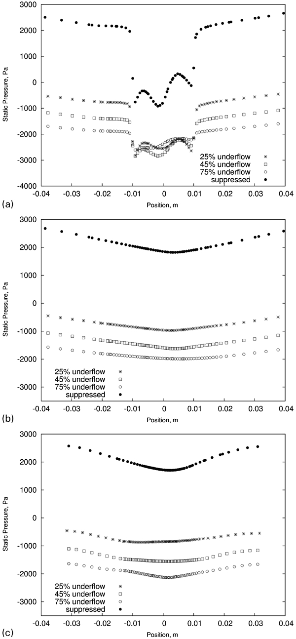
Static pressure plot at a horizontal plane y = 0·1405 m at VF tip for conical design for conical design, b horizontal plane y = 0·07 m in cylindrical section for conical design and c horizontal plane y = −0·16 m in conical section for conical design
Comparison between conical and flat bottom cyclone
A comparison of the velocity plots at the VF tip is shown in Figs. 9 and 10. The figures show the axial velocity and radial velocity at a horizontal plane y = 0·1405 m for the conical and at z = 0·138 m for the flat bottom cyclone with 25% underflow split respectively. The reduced axial velocity at the tip of the VF in the conical cyclone reduces the intermixing of the high density particles in the overflow, enhancing the separation.
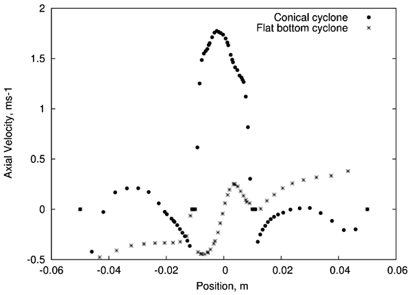
Axial velocity at horizontal plane at VF tip for conical and flat bottom designs
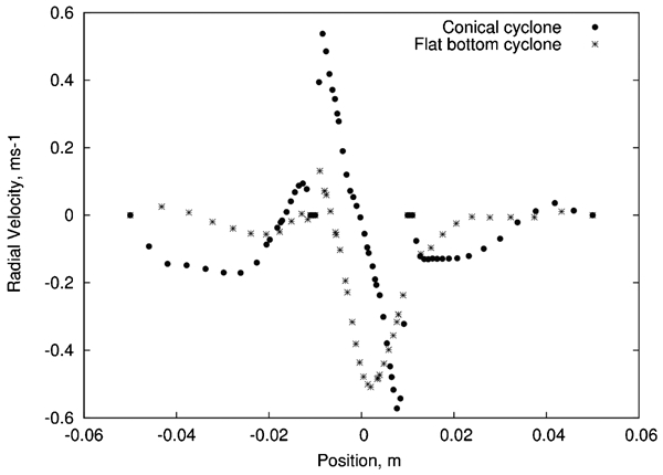
Radial velocity plots at horizontal plane at VF tip for conical and flat bottom designs
Particle separation
The separation efficiency curve expresses the percentages of different specific gravity particle reporting to the overflow with respect to that in the feed. A plot of the % recovery in overflow against the specific gravity of the particle is given in Fig. 11. It is commonly used to present the performance of a dense medium cyclone for a coal washing plant. Its prediction requires a method for tracing particle trajectories as affected by the predicted axial, tangential and redial velocity components. In order to trace the particle trajectory, the particle velocities were obtained from the fluid velocities using the particle momentum equation (2) with the drag force per unit particle modelled from equations (4) and (5). The trajectory of a particle depends on the location at which it enters hydrocyclone. Assuming that all particles in the feed stream, despite their difference in size and density, have the same probability of entering the hydrocyclone through any of the entry points, it is possible to determine the trajectory and eventually to compute the particle separation efficiency.
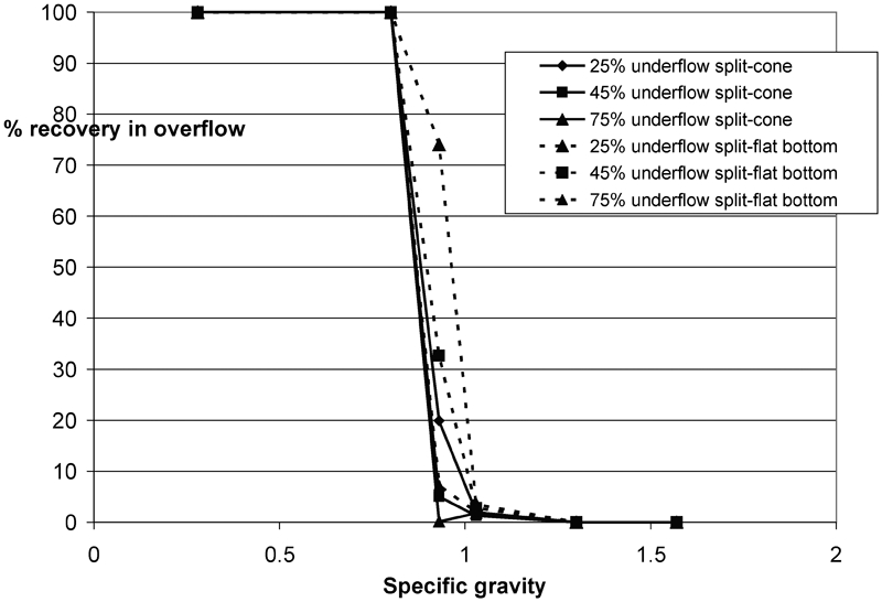
Separation efficiency curves at different underflow splits for conical and flat bottom designs
As was seen in the experiments, the cyclone with the inserted rod and that with 25% underflow split gave the best separation efficiency. The reasons for this, as discussed in the section on ‘Fluent results’, are as follows:
the cyclone with the inserted rod and the 25% underflow split case reaches a higher maximal tangential velocity. The higher the tangential velocity, the higher the centrifugal force imposed on the separated particles. The increase in the tangential velocity helps in better redistribution of the internal energy
the decrease in the axial velocity of fluid nearby the entrance of the vortex finder is beneficial to reducing the mixing of high density particles in the overflow product. Also in the region of the vortex finder, the high axial velocities help in carrying the lighter particles to the overflow product faster
the reduction in radial velocity towards the centre is advantageous for separating lighter particles because the drag forces, acting towards the centre, are reduced.
Conclusion
Tests were carried out in a 100 mm Perspex model with water as the fluid and density tracers with specific gravity above and below that of water. The effect of different operating and design variables on the formation of air core was studied. Test work was carried out using design of experiments and the results analysed statistically. The results showed that % underflow split was the most important variable affecting the air core formation.
The air core was found to affect the separation of lighter particles with specific gravity closer to the fluid. Better separation of the particles was obtained before the formation of air core.
The air core was suppressed using a metal rod inserted in the conical half of the cyclone and the studies carried out. Suppressing the air core gave the maximum % recovery of particles in the overflow followed by the cyclone with 25% underflow split.
Numerical simulation studies showed that the higher recovery of particles was due to the higher tangential velocities and lower radial velocities.
The higher tangential velocities and the lower radial velocity helped in better separation because of the higher centrifugal force and lesser drag force preventing the misplacement for heavier particles to the overflow.
The conical cyclone gave better separation than the flat bottom design.
The studies promise scope in designing a new design of a dense medium cyclone with a suppressed air core that can improve the recovery of the particles with specific gravity close to that of the medium. The cyclone could play an important role in the coal washing industry in future.