
Abstract
The freeze lining of an industrial copper flash smelting furnace slag, its growth kinetics and microstructure have been studied using a water cooled probe technique in a rotating crucible furnace at 1350°C. The first layers of iron silicate slag solidify on the water cooled metal surface as amorphous or glassy material with a minor fraction of crystalline spinel phase precipitated. At a distance of 4–5 mm from the cold face about 50% of the structure is composed of crystalline olivine (fayalite) and spinel phases embedded in a glassy matrix. Major thickness of the freeze lining is formed within first 15 min of slag contact with a cooled metal surface. The solidified microstructures obtained were compared with equilibrium phase assemblages calculated. The equilibrium solidification in the near solidus reactions includes the formation of pyroxene and rhodonite type phases, but they were not identified in the lining microstructures.
Introduction
Several authors have investigated freeze lining properties and their formation mechanisms in a number of environments. Most early studies (Thonstad and Rolseth, 1996; Voller, 1996; Solheim and Støen, 1997) deal with the Hall-Héroult aluminium smelting cell and its pot lining. Recently, the freeze linings formed in lead and zinc smelting slags have been studied (Verscheure et al., 2006a; Campforts et al., 2007a, 2008, 2009a, 2009b, 2009c, 2009d). Mathematical models have been developed for describing the behaviour of freeze lining in dynamic conditions (Scholey et al., 1991; Campbell et al., 2001; Verscheure et al., 2005, 2006b; Zietsman and Pistorius, 2006; Guevara, 2007). No experimental study on freeze linings in copper smelting slags or environments is available in the literature.
The aim of this study was to investigate the growth kinetics of an iron silicate slag freeze lining in typical copper matte smelting conditions. Industrial iron silicate slag from an industrial flash smelting furnace (FSF) has been used as the lining forming medium. Water cooled probe technique by Verscheure et al. (2006a) was applied in a rotating crucible, for stabilising temperature profile of the slag bath.
Experimental apparatus
The experimental device was a vertical 25 kVA MoSi2 resistance heated furnace, as shown in Fig. 1, with a maximum temperature of 1700°C and a φi = 110 mm rotating disc pedestal that can be lifted into the furnace. The furnace was manufactured by Entech AB (Ängelholm, Sweden). The furnace cap (a) and the pedestal (c) were made of an insulating fire brick and insulating refractory fibre plate. The rotating disc acts as a pedestal for the crucible (b) and as insulation and temperature shield in the bottom of the furnace. The disc and crucible were fixed together using alumina cement.
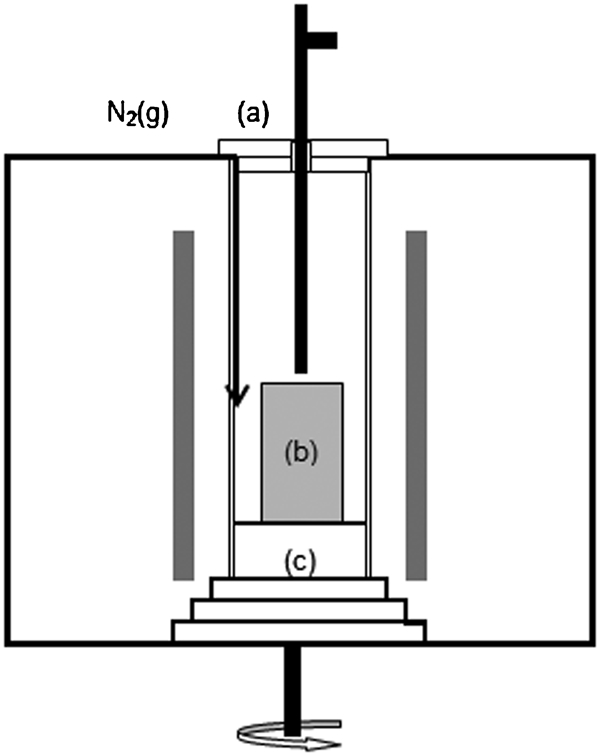
The experimental furnace: the probe and the cap through which the probe is lowered into the furnace are shown schematically; the black arrow indicates the nitrogen flow into furnace
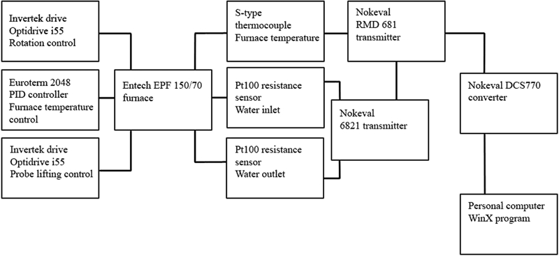
The furnace temperature was regulated with a programmable Eurotherm 2048 PID controller. Invertek Optidrive i55 inverters were used to control the rotation speed of the crucible (0–25 rev min−1) and the moving rate of the probe.
Class A Pt100 sensors were used to measure the inlet and outlet water temperatures of the cold finger, mounted in its upper end. Their length was 100 mm and diameter 3 mm, with the sheath of AISI 321 steel. A four-wire mode was used to connect them to a Nokeval 6821 (Nokia, Finland) transmitter, which passed the data to a DCS770 data logger for forwarding to a PC. The maximum error of the sensors at 0°C was 0·15°C, and that of the transmitter was 0·05% of the measured value, meaning 0·025°C at 50°C.
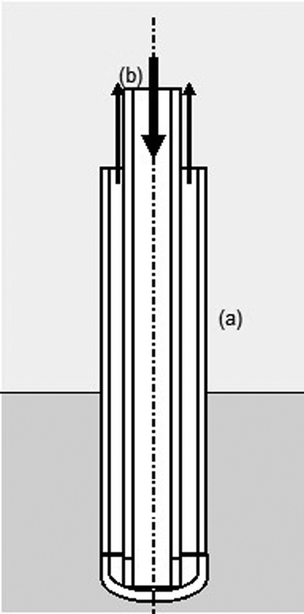
Water flow into the probe was adjusted by controlling water pressure in the probe with manual valves. The probe used in experiments #1–9 was φo = 22 mm and the inner tube for water feed to the tip was φo = 8 mm. It was 600 mm long. The probe and the inner sheath were made of AISI 316L stainless steel and the walls were 1 mm thick. The probe used in experiments #10–13 was similar in design, but the outer tube was φo = 14 mm and it was 700 mm long. Schematic construction of the probe is shown in Fig. 2. In experiments #7–13, the probe was insulated with a Kaowool fibre rope supplied by Thermal Ceramics (UK), starting 100 mm upwards from the tip of the cold finger.
Schematic picture of water cooled probe used in experiments. Water flow's direction is presented with arrows: (a) outer AISI 316L steel tube; (b) inner AISI 316L steel tube
The probe was lowered and lifted with an electric motor. A S-type (Pt10%Rh/Pt) thermocouple measured temperature above the crucible for safety precautions. An 8 channel Nokeval RMD 681 transmitter was used to convert its EMF to computer via the DCS770 unit. A general wiring diagram of the system can be seen in Fig. 3.
Schematic wiring diagram of experimental setup for temperature measurements and for furnace control
Dense cylindrical 99·4% MgO crucibles supplied by Ozark Technical Ceramics Inc. (MT, USA) in different sizes were used. Nitrogen gas with a purity of 99·9%, containing <20 ppm O2 and <10 ppm H2O, was used in all experiments as protective atmosphere for avoiding any oxidation of the slag during the experiment. The flowrate of nitrogen to the furnace varied in the experiments from 3 to 6 dm3 min−1 (STP).
The solidified freeze linings were broken for preparation of samples from the top and bottom parts. The specimens were examined with a LEO 1450 scanning electron microscope with a tungsten cathode, in backscattered electron mode using 15 kV acceleration voltage. The microstructures and compositions of the phases were determined with an INCA X-Sight 7366 EDS-analyser from polished sections, prepared using standard wet methods. SPI Supplies Inc. (PA, USA) mineral standards were used for the elements analysed by EDS.
Methods and Procedures
The crucible containing 1·5–2 kg crushed slag, depending on its diameter, was placed on the rotating pedestal. The furnace was then heated at a rate of 4°C min−1 to experimental temperature of 1350°C. The rotational speed of the crucible and the furnace temperature were kept constant. The probe pressure was adjusted so that the cooling water flowrate was 2·1–2·8 dm3 min−1. The water pressure in the probe was kept constant in each experiment.
After reaching the set temperature, the system was allowed to stabilise for 30 min, with the rotational speed adjusted to 10 rev min−1. After 15 min, the water cooling of the probe was started in order to maintain steady state in its temperature profile. During the stabilisation period, the water flowrate was measured. After the 30 min period, a start composition sample of the slag was taken with a steel dip rod and quenched into water.
The probe was then lowered into the furnace over an approximate time interval of 6 min. Its tip was submerged about 5 cm into the melt. After the dip time, varying from 2 to 90 min, the probe was lifted quickly from the furnace and the solidified sample was quenched in water.
Post quenching, the sample was loosened from the probe by hand and placed on a refractory brick for final cooling in air. After lifting the probe from the furnace, the end composition sample was taken from the melt with a steel dip rod and quenched into water. Samples were also taken from the slags cooled in flowing nitrogen along with the furnace.
Raw materials
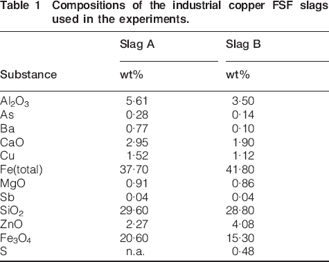
The slags used in experiments #1–10 and #11–13 are denoted as slag A and slag B respectively. The slag, collected from the cooling yard of the copper smelter, was crushed down to a few millimetres and homogenised by blending. Chemical compositions of the slags A and B are presented in Table 1. The target matte grade produced at the smelter was 65%.
Compositions of the industrial copper FSF slags used in the experiments.
Microstructure
Scanning electron micrographs of the lining samples were taken carefully in sequences, in order to cover the whole thickness of the freeze layer. It was thought that the samples from the lower end of the cylindrical probe represent the formed freeze lining better because the heat from the furnace walls through the slag upper surface does not affect it so much.
Microstructure panoramas were compiled from the sequences with Adobe Photoshop CS. The panorama pictures contain the whole lining beginning from the probe surface and ending finally at the hot surface. The strips are separated with a thin horizontal white line and each micrograph shows the continuous lining from left to right. Each strip is ∼1 mm in length.
Chemical analyses
After quenching in water, the solids were filtered using a funnel and filter paper, followed by a 24 h drying in an oven at 60°C in air. The dry samples were enclosed into plastic sample bottles and sent to chemical analysis. The start and end composition samples were analysed chemically at Outotec Research Oy (Pori, Finland).
The raw materials and samples were analysed for aluminium (Al), arsenic (As), barium (Ba), calcium (Ca), copper (Cu), iron (Fe), magnesium (Mg), zinc (Zn), lead (Pb) and sulphur (S). Sulphur was determined with an Eltra CS2000 S/C analyser and SiO2 by colorimetric techniques. Fe3O4 was determined with a Satmagan analyser. The other elements were analysed using an Iris Intrepid II XDL inductively coupled plasma spectrometer.
Results
A typical freeze lining sample macrostructure is shown in Fig. 4. The thickness of lining varied according to the submergence time. As shown in Fig. 4, the linings were black in colour, their surfaces were shimmering and mostly rough. The fast cooled sample material crumbled easily, whereas the slowly cooled slag in the crucible was hard to break.
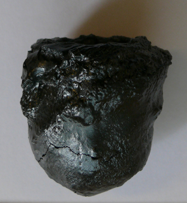
Typical freeze lining sample after quenching to room temperature (from run #6)
The lining microstructures were found to consist of four main phases: an amorphous matrix, spinel crystals with high iron content (primary and secondary magnetite Fe3O4), fayalite ((Fe, Mg)2SiO4 or olivine solution phase) crystals, white droplets of metallic copper and cuprous sulphide. The four identified phases and their characteristic morphologies are shown in Fig. 5. Their grain size and occurrence vary greatly as a function of the distance from the cooled probe surface and contact time. The characteristic morphologies are: magnetite dendrites (Fig. 5(b)), fayalite ‘columns’ (Fig. 5(d)) and copper matte-metal droplets (Fig. 5(a)). Very small (<1 μm) copper-rich particles were also detected in the glassy matrix. They obviously form in the final solidification, as ferric oxide stabilises reducing cuprous oxide from the molten silicate, as demonstrated by Subramanian and Themelis (1972).
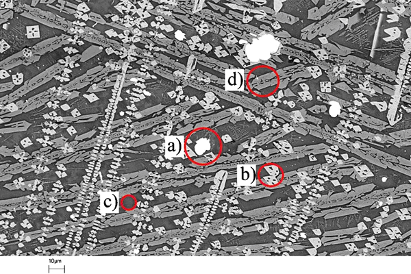
Typical microstructure and phase morphologies found in iron silicate slag freeze linings: (a) a droplet with a high copper content, (b) a magnetite dendrite, (c) amorphous matrix, (d) fayalite ‘column’ (run #8); scale bar is shown in lower left corner
Some pores were also found to be present in the freeze linings at a constant distance from the probe. The pores were visible in black in the microstructure and their presence was confirmed with secondary electron micrographs.
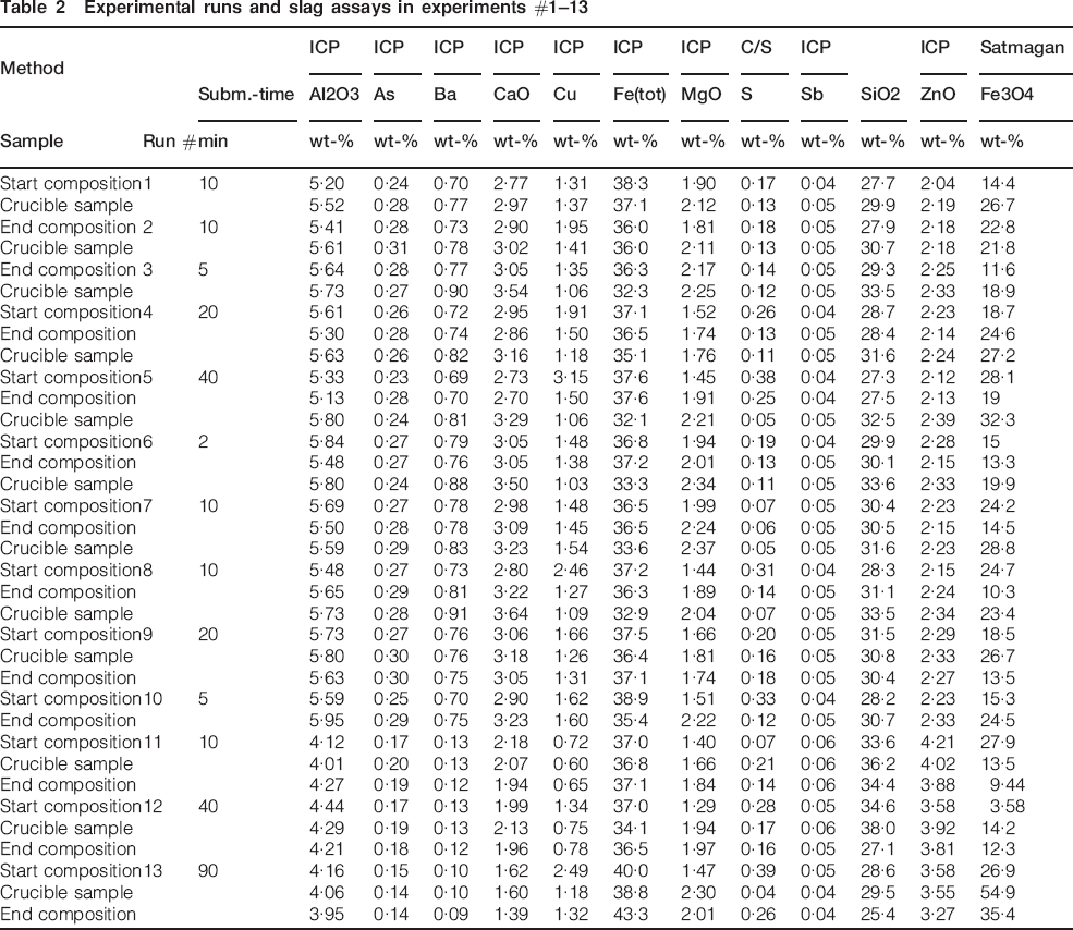
The average MgO concentration of the slag after each run was less than 1% higher than the initial slags A and B (Table 2). It indicates that the selection of dense MgO as the crucible material was successful and the material can be used in contact with the reactive iron silicate slag melts for extended periods of time, without serious contamination. Table 2 also shows that the protective N2 atmosphere has been effective enough to maintain oxidation degree of the slag constant throughout the experiment, as indicated by its magnetite analysis.
Experimental runs and slag assays in experiments #1–13
Structure of the freeze lining
Examples of the panoramas obtained are shown in Fig. 6a and b. They were linked together with the SEM-EDS data to establish the lining composition as a function of distance, the zero distance being the cold probe surface. From each panorama, two diagrams were drawn: one with the SiO2 and Fe contents in the matrix and the other with its Mg, K, Ca, Na and Al contents as a function of distance. Typical examples of the composition profiles are shown in Figs. 7 and 8.
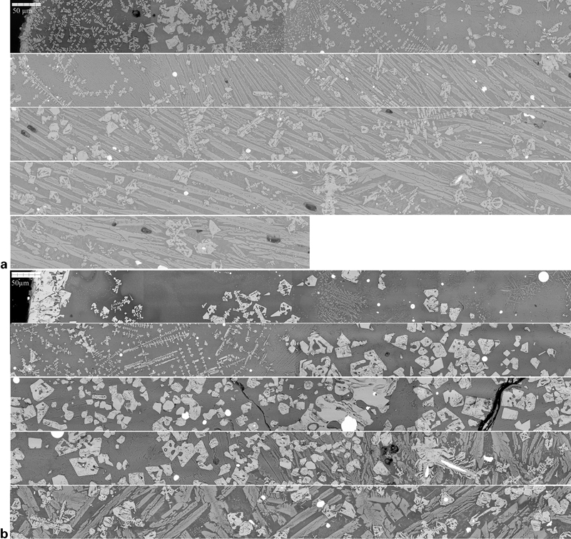
a panorama of the freeze layer: cross-section structure of cold end in run #5 with submergence time of 40 min; four full strips continue from upper left (cold face) to lower right (hot face), each strip is ∼1 mm thick in radial direction of the lining and b structure of the freeze layer obtained in run #8 with submergence time of 10 min; the section is an example of a freeze lining cold end with fully amorphous structure, without any magnetite precipitates next to the cooled metal surface
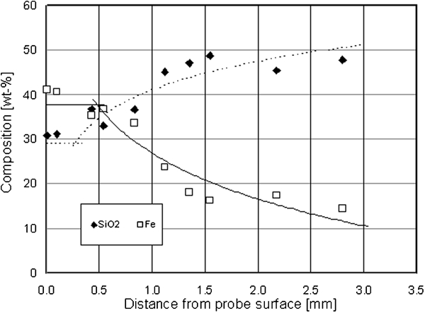
SiO2 and Fe concentrations of the glassy matrix as a function of distance from the cold probe surface; note the fast cooled inner layer of the freeze lining with the initial slag assay (run #7) shown as the horizontal lines
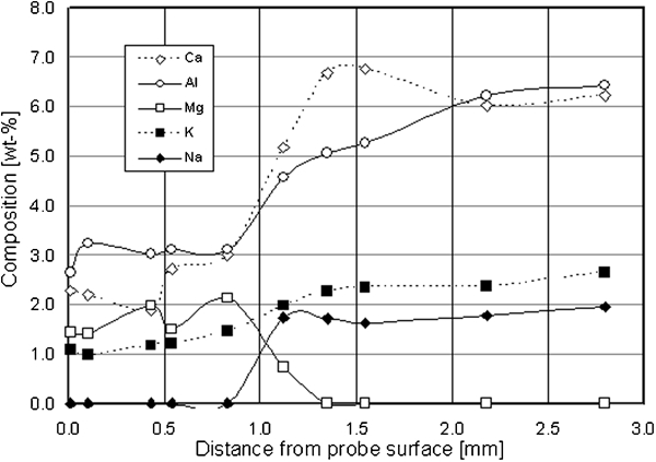
Mg, K, Ca, Na and Al concentrations of the lining matrix (in run #7) as a function of distance from the cold surface; note the inner completely quenched layer of the freeze lining extending 1–1·5 mm from the probe surface
Total iron concentration Fe(tot) of the matrix next to the probe is close to the average slag composition, as seen in Fig. 7 and Table 1, but clearly lower towards the hot end of the lining, around 10–15%, due to precipitation of magnetite and olivine. The slag has a total iron concentration of 37·7%. This feature obviously indicates the difficulty of iron oxides to diffuse rapidly enough in the first seconds of solidification. Silica concentration of the glassy matrix deeper in the freeze lining is correspondingly high, above 50% SiO2 and thus supersaturated by about 10%, due to the slow precipitation rate of silica, when the average slag silica is only ∼30%.
It was noted that Al, Ca and K concentrations of the glassy matrix follow the same pattern, as shown in Fig. 8. Also here, a thin amorphous layer of about 1–1·5 mm having initial composition of the FSF slag is clearly seen. The fully quenched glassy layer thickness was slightly larger 1·5–2 mm, when φ 22 mm cold finger was used instead of 14 mm. The oxide composition of the amorphous inner surface layer of the lining was close to the average slag assay, except for MgO which is enriched by a factor of 2. Sodium, but not potassium, also seems to move fast in the zone, as many sections indicate that its concentration is much lower than the average slag composition.
It is also obvious that MgO concentration of the matrix goes close to zero after reaching a distance of approximately 1–2 mm from the cold face, forming an MgO depleted zone, due to predominant dissolution in the olivine phase. The MgO is again present in the matrix beyond a distance of approximately 8–10 mm, depending on the probe diameter.
Based on these observations, it is obvious that the diffusive transport of iron (oxides) is not very fast in the solidifying iron silicate slag and a thin layer against the cold metal surface has mostly solidified in amorphous state, as also demonstrated by Campforts et al. (2007b, 2009a) in synthetic low-in-silica lead slags.
The crystalline phases of the lining, magnetite and olivine, contain small concentrations of slag constituents they are capable to dissolve during the relatively rapid solidification. The magnetite crystals contain 2–3% Al (3–5·5% Al2O3), 0·3–0·8% Ca (0·4–1·0% CaO), 0·5–1% Mg (0·8–1·5% MgO), 1–3% Si (2–4·5% SiO2) and 1–2% Zn (1·2–2·5% ZnO), but no copper. The columnar olivine crystals were analysed to dissolve about 3% Al (5·5% Al2O3) and 0·5–1% Mg (0·7–1·7% MgO). The cross-sections of olivine also indicate compositional differences between the first solidified core and the surface due to MgO concentrations, as can be seen in Fig. 5 and the contrasts in olivine phase.
As the crystalline phases formed in the lining do not contain significant fractions of lime, it is concentrated in the glassy matrix as shown in Fig. 8. The lime concentration in the glassy phase is 2–3x the average slag composition, but in the proximity of the cold surface the EDS analysis is a good agreement with the chemical assay.
Freeze lining growth kinetics
The dimensions of the linings were measured with a slide gauge post-experiment. The probe diameters were subtracted from the measured outer diameter values. For the measurements from samples with the same submergence time (10, 20 and 40 min), the thickness at 50% immersion depth was used. The lining growth kinetics of the 14 mm probe is shown in Fig. 9.
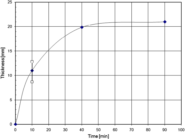
Freeze lining growth as a function of time (φo 14 mm cold finger, at 50% immersion depth); the experimental scatter is shown at 10 min immersion time
Figure 9 indicates that the mean lining thickness increases along with time until about 40 min of the submergence time and contact with the cooled metal surface, when 14 mm probe was used. However, there is only a slight difference between the maximum thicknesses at submergence times of 40 and 90 min. The 22 mm probe did not reach steady state conditions with the 40 min submergence time, before the lining growth reached the crucible walls.
Discussion
The observed microstructures of the freeze lining of an iron-silicate copper FSF slag obtained were compared with the calculated equilibrium phase assemblages of the same slag assay. The phase equilibria in solidification were calculated using Mtox 6·2 database by NPL-MIRO (Gisby et al., 2007) The starting point of calculations, the analysed composition for slag A, was simplified by omitting minority components As and Sb in the assay (Table 1). Barium was also added to the lime concentration, and copper was divided between sulphide (as Cu2S) and oxide (as Cu2O), based on the sulphur analysis. Finally, the component substances were normalised to 100%.
The computational system consisted of 49 substances, including 35 non-ideal mixture phases and 14 pure substances, formed by thermodynamic components of the system Al2O3, CaO, Cu2O, FeO, Fe3O4, MgO, SiO2, ZnO and Cu2S. No gas phase was defined to the system. Miscibility gap was defined in five solution phases.
The primary phase in the solidification spinel solution, often simplified as ‘magnetite’, has a complicated sublattice structure in the database. It can be written as (Al3+, Cu2+, Cu+, Fe3+, Fe2+, Mg2+, Zn2+)1(Al3+, Ca2+, Cu2+, Fe3+, Fe2+, Mg2+, Va)2(Fe2+, Mg2+, Va)2(O2−)4, where Va denotes vacancy in a sublattice (MTOX, 2009). The solidifying slag at ∼1115°C gets saturated with olivine solid solution or ‘fayalite’, with the sublattice structure of (Ca2+, Cu2+, Fe2+, Mg2+, Zn2+)1(Ca2+, Cu2+, Fe2+, Mg2+, Zn2+)1(
 )2. Silica in equilibrium conditions precipitates from the molten slag A at 1110°C.
The equilibrium solidification process was calculated with MTDATA (Version 5·01) using its multiphase module (MTDATA). The calculations were carried out from 1350 to 900°C at 1°C intervals.
Solidification phase equilibria
Two cases were evaluated: the first involves the possibility of silica (‘quartz’, ‘cristobalite’ and ‘tridymite’, in this system stoichiometric SiO2) to be stabilised in the system, whereas in the second case its presence in the equilibrium phase assemblage has been suppressed, together with rhodonite.
The molten slag phase meets the liquidus surface at ∼1330°C, and magnetite precipitates as primary phase. The calculated phase equilibria, depicted as masses of the stabilising phases at each temperature, are shown in Figs. 10 and 11 over a temperature interval of 900 to 1350°C.
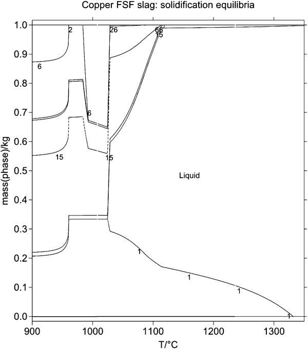
Equilibrium phase assemblage of copper FSF slag A at 900–1400°C; phase labels: 1, 2 – spinel, 6 – clinopyroxene, 15 – olivine, 26 – rhodonite and 66 – tridymite, unlabeled phase stabilising at high temperatures is copper matte and alloy
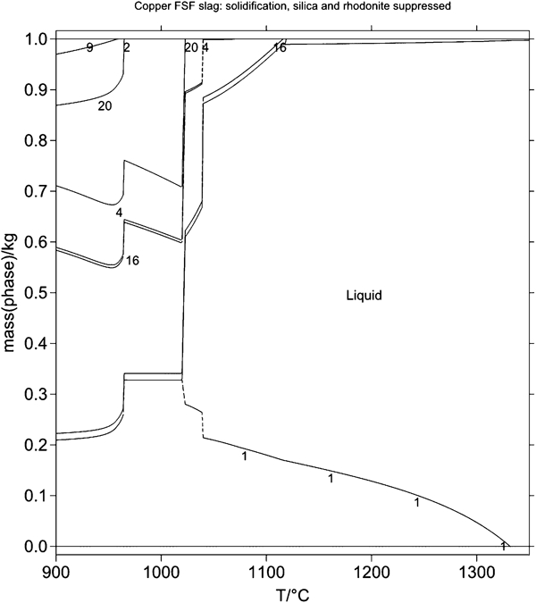
Calculated phase assemblage of copper FSF slag A at 900–1400°C in case II, where silica and rhodonite are not allowed to stabilise during solidification; phase labels: 1, 2 – spinel, 9 – feldspar, 16 – olivine and 20 – wollastonite
Solidus temperature of the slag is 1030°C, where rhodonite with the sublattice structure (Ca2+, Fe2+, Mg2+)1(
 )1 is precipitated in the final solidification reactions, close to the solidus temperature. The spinel solution phase decomposes partly in sub-solidus reactions, and a clinopyroxene solid solution, also known from its end members ‘augite’, ‘clinoenstatite’ or ‘diopside’, with the sublattice structure of the type (Ca2+, Fe2+, Mg2+)1(
 , FeSi6+, FeSi7+, MgSi6+)1(
 )1, is formed, when the rhodonite solid solution decomposes at ∼1000°C (Fig. 10). Small fractions of copper and copper sulfides are stable over the whole temperature interval, showing the fact that in FSF the slag indeed was saturated with matte.
When the formation of silica and rhodonite are suppressed, after spinel only olivine solid solution precipitates at 1115°C, and solidus reactions at 1040–20°C should create pyroxene-type silicates and wollastonite if the residual melt would crystallise (Fig. 11).
Freeze lining microstructures
In the literature, there are available several studies concerning the formation and properties of freeze linings in a number of metal making technologies. However, no straight comparisons with this study can be found in the literature, because none of the previous investigations have been carried out with the high-iron silicate type slag as used in this experimental series. The second difference is the oxidation degree of the slag, which in this case was relatively high as to a technically pure iron silicate slag. It is characterised by the Fe3+/Fe2+ ratio of the slag and by its magnetite concentration, but from thermodynamic point of view controlled in FSF by the produced matte grade and silica concentration.
The inner freeze lining zone of a few millimetres in thickness is largely amorphous with an essentially same assay as the average molten slag. It contains randomly distributed and aligned magnetite crystals, which have a volume fraction of less than 10%. In some locations, however, large magnetite crystals precipitate at the cold interface causing at the same time large volumetric differences (MTOX, 2009) between the phases (
 ≈4·8 g cm−3 at 1200°C and ρslag ≈2·7 g cm−3) and thus stresses in the freeze lining. Towards the hot end of the lining, the volume fraction of crystalline phases grows rapidly and long olivine crystal columns and magnetite dendrites is above 50% at distances of 4–5 mm from the cold surface and beyond. The thickness of the fully amorphous quenched zone depends on the cooling effect of the probe and thus on the cold finger diameter.
A comparison of the freeze lining microstructures obtained with the calculated equilibrium structures reveals that only magnetite and fayalite precipitate from the iron silicate copper FSF slags, when the autogeneous lining is formed on a water cooled metal surface. The pyroxene type silicate phases, as shown in Figs. 10 and 11, or rhodonite as well as feldspar forming close to or during the final solidification of the slag are in essence absent in the formed freeze linings.
Kinetics of the freeze lining formation in FSF
The only previous study on freeze linings in copper matte smelting environments16 deals with electric furnace smelting of sulphide concentrates, and includes low temperature scale modelling observations of the lining formation. This study discloses the first experimental results available on the kinetics and microstructure of industrial copper matte smelting slags at typical flash smelting temperatures.
The growth kinetics of an iron silicate slag freeze lining in FSF copper matte smelting conditions having a moderate overheating of ∼20°C, the temperature difference between the liquidus temperature and the experimental temperature, is very rapid. The first moments of the slag contact with the cooled metal surface increase the freeze lining thickness to 15–20 mm within 10–20 min, which is important feature from the industrial point of view and the smelting furnace and their copper cooler integrity (Fagerlund et al., 2010). The cooling capacity of the cold finger determined essentially how fast the freeze lining growth reaches the steady state in the case of a freeze lining failure. With our 14 mm water cooled probe, the steady state lining thickness of about 20–22 mm was reached within 40–60 min of submergence, whereas the growth with the 22 mm probe continued still at a reasonable rate after 40 min. The steady state thickness of the freeze lining is of the same order of magnitude as observed in lead smelting and zinc fuming slags by Campforts et al. (2007a, 2009c).
The thermal shock of the slag contact to the cooling device by release of the latent enthalpy of solidification was clearly observed in the heat flow measurements to the probe. The duration of the excessive heat flow to the probe was less than 60 s, during which the heat flux was 4–5 times the stationary value.
Conclusion
The freeze lining formation in an industrial copper FSF slag, its growth kinetics and microstructure have been studied using a water cooled probe technique at 1350°C, applying a rotating crucible for stabilising the temperature profile. The new furnace design was successfully tested with two probe sizes of 14 and 22 mm in diameter with submergence times from 2 to 90 min. Dense MgO crucibles proved to be suitable for this type of reactive high-in-iron silicate slags, due to the very small dissolution rate of the material during the test periods of up to 2–3 h in contact with the molten slag. It was confirmed that increase in its magnesia concentration was less than 1% in all cases.
The copper smelting iron silicate slags form freeze linings at a high initial rate and the first 10–15 mm thickness is solidified within 10–20 min of submergence. Very thin and fully amorphous zone of 1–2 mm is formed against the cooled metal surface, and well developed, mostly crystalline lining forms from 3–4 mm onwards, depending on the heat flux to the cooled metal surface. The crystalline phases identified in the linings post-submergence were magnetite (a member of the spinel solid solution) dendrites and fayalite (an end member of the olivine solid solution) columns embedded in the intergranular glassy matrix.
Equilibrium solidification of the industrial slag used in the experiments occurs with magnetite as the primary phase, followed by precipitation of fayalite and silica. As solidus reactions, the slag forms rhodonite and pyroxene type silicates in equilibrium conditions. Only magnetite and fayalite were identified in the freeze linings, together with entrained copper matte droplets and metallic copper.
Footnotes
Acknowledgements
The authors are indebted to Outotec Research Oy for the full financial support of this work, for carrying out the chemical analyses of the slag samples and for delivering the raw materials. The technical guidance of the project by Dr Tech Matti Luomala is kindly acknowledged as well as the permission of Outotec Research Oy to publish this paper.