
Abstract
In this study, we have experimentally and numerically studied fluid flow behaviour in industrial Peirce–Smith converter (PSC) using cold model simulations. The two- and three-dimensional simulations of the three phase system were carried out using volume of fluid (VOF) and realisable k–ϵ turbulence model to account for the multiphase and turbulence nature of the flow respectively. These models were implemented using commercial computational fluid dynamics (CFD) numerical code FLUENT. The cold model for physical simulations was a 1∶5 horizontal cylindrical container made of Perspex with seven tuyeres on one side of the cylinder typifying a PSC. Compressed air was blown into the cylinder through the tuyeres simulating oxygen enriched air injection into PSC. Industrial treated feed, product and byproduct referred to as matte-white metal and slag were simulated with water and kerosene respectively in this study. The influence of blowing conditions on the distribution of phases was studied with five different compressed air volumetric flowrates at constant simulated matte and slag ratios. Both numerical and experimental simulations were able to predict the dispersion characteristics of the system in relation to flow and have substantially added to the understanding of the fluid dynamics of PSC.
List of symbols
characteristic diameter, m
average diameter of dispersed phase droplet, m
gravitational constant, m s−2
turbulent kinetic energy (m2 s−2)
model characteristic length
prototype characteristic length
morton number

modified Froude number
mass source term
velocity, m s−1
volume of simulated matte, simulated slag, m3
ith fluid's volume fraction in the cell
turbulent dissipation energy, m2 s−3
surface tension, N m−1
slag surface tension, matte surface tension
matte-slag interfacial tension
density of gas, simulated matte, simulated slag, kg m−3
scale factor
dynamic viscosity, Pa s
Introduction
Peirce–Smith converter (PSC) is cylindrical horizontal reactor (circular canal geometry) where air at subsonic velocity is injected into copper matte through submerged tuyeres which come along the axis of the converter (Gonzalez et al., 2008). Peirce–Smith converter has been used in the copper making industry for more than a century for the purposes of removing residual iron and sulphur impurities to obtain blister copper through exothermic chemical reactions, a process step referred to as conversion (Liow and Gray, 1990; Real et al., 2007). This process is semicontinuous and auto-thermal.
The conversion process used in removing residual iron and sulphur content in matte is a complex phenomenon involving phase interactions, many chemical reactions, associated heat generation as well as product formation (Kyllo and Richards, 1998a, 1998b). Despite substantial amount of PSC operational existence, there has been an insufficiency of research on process engineering which lower considerably the productivity of the process. Mixing and mass transfer in the converter are such key tenets process parameters that have been little studied. Most of research on mixing and injection phenomena in gas/liquid multiphase systems has been conducted in the steel making and ladle metallurgy (Sahai and Guthrie, 1982; Sinha and McNallan, 1985; Mazumdar and Guthrie, 1986; Castillejos and Brimacombe, 1987; Stapurewicz and Themelis, 1987; Kim and Fruehan, 1987). Due to similarity of the basic concept in ladle injection and PSC, the core tenets of the works have been adopted in the past decades on process characterisation research of PSC in an exertion to address the challenges in productivity (Hoefele and Brimacombe, 1979; Gray et al., 1984; Vaarno et al., 1998).
The injected air has twofold functions which are: supply of oxidant (reactant) and energy to stir the bath. Energy is supplied in three forms namely kinetic, buoyancy and expansion. The mentioned functions affect the chemical and physical processes occurring in the converter such as converting rate, oxygen efficiency, dispersion, mixing, heat and mass transfer, slopping, splashing and accretion growth (Haida and Brimacombe, 1985; Valencia et al., 2004).
Since there are chemical reactions taking place with products being formed; quality and quantity of mixing is important. Mixing will promote chemical reactions, removing the products from reaction sites; minimise temperature and composition inhomogeneties (Sinha and McNallan, 1985; Mazumdar and Guthrie, 1986). Due to generation of turbulence in the converter, mixing may aid inclusion agglomeration, coalescence and floatation of impurities, thus improving converter efficiencies (Mazumdar and Guthrie, 1986; Gray et al., 1984).
Macroscopic physical and numerical models of PSC have been developed to study multiphase fluid flow phenomena (Gonzalez et al., 2008; Liow and Gray, 1990; Real et al., 2007; Vaarno et al., 1998; Valencia et al., 2004; Valencia et al., 2004; Koohi et al., 2008; Rosales et al., 2009). However, despite the bulk of numerical and experimental work on the subject of fundamental phenomenon of multiphase flow, little effort has been addressed to the understanding of the complex phase interactions of the three phase system in terms of volumetric proportionation (dispersion) with relation to the flow conditions presented by tuyere specific power. Dispersion is a subject that needs further understanding as there are quite substantial amounts of valuable metal losses due to entrapment, a situation that has lead to the incorporation of slag cleaning systems in the copper production circuits (Moreno et al., 1998; Warczok et al., 2004).
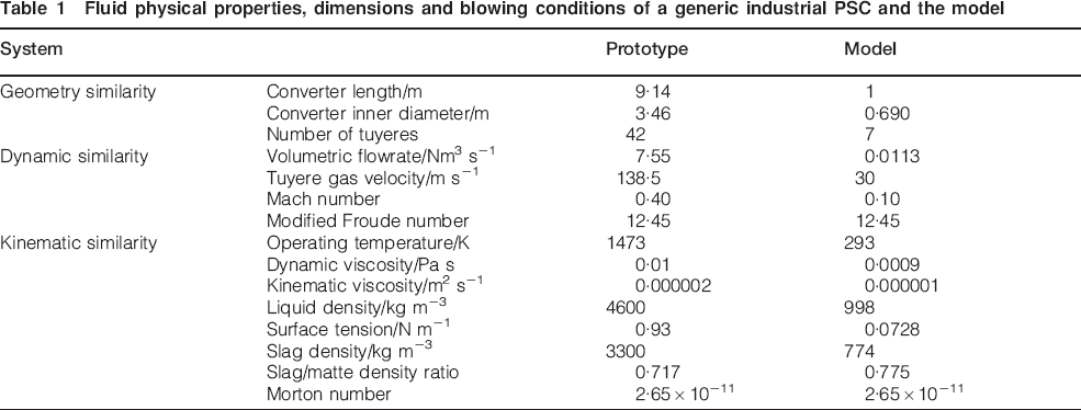
Against such background, in this work, we investigate the dependence of dispersion of simulated matte-white metal and slag to operating system variable volumetric gas flowrate. A 1∶5 water bath physical model of equivalent properties as the generic industrial PSC to carry out the experiments was designed using similarity principles. Geometric, dynamic and kinematic similarity were used in the design for equivalency between prototype and model since hydrodynamic studies on fluid flow are not concerned with thermal and chemical similarity effects (Mazumdar, 1990).
Due to fluid flow physics phenomena under current study, the dynamic similarity (blowing parameters) and the reliability of the physical model were determined using modified Froude number, Nfr* which resembles fluid flow dominated by inertial and gravitational forces which are more pronounced than molecular viscous forces (Mazumdar and Evans, 2004). The molten liquid phases in the real PSC namely matte-white metal and slag were simulated in the model with water and kerosene respectively due to kinematic similarity.
Due to scarcity of quantitative research work to date on PSC, an overall strategy has been devised to explain and evaluate experimental results using numerical simulation of the converter through computational fluid dynamics (CFD) software. Vaarno et al. (1998) and Valencia et al. (2004) evaluated the applicability of mathematical formulation to the PSC process using cold model experiments with success and established velocity vector fields. In a similar study, (Vaarno et al., 1998; Valencia et al., 2004) studied the influence of Froude number on bath mixing, jet stability and splashing in a PSC using mathematical formulation and cold model experiments. This work presents a first attempt to study dispersion and interaction of phases in the PSC.
Isothermal transient multiphase two-dimensional (2D) and three-dimensional (3D) CFD numerical simulations were carried out. The CFD numerical code FLUENT software was used to solve the transient Navier–Stokes equations. The realisable k−ϵ turbulent model and infinitesimal fluid element also known as volume of fluid (VOF) was used to model the turbulence nature and multiphase flow respectively.
Experimental technique
Cold model studies were carried out in a horizontal Perspex cylinder, which is a slice of 1∶5 model of the generic commercial PSC. It has an internal length of 1000 mm and an internal diameter of 690 mm with seven tuyeres (air inlet tubes were compressed air is purged into the model) on one side of the vessel, each with an internal inlet diameter of 8 mm. The model was fitted to a steel cradle to minimise vibration effects on the model superstructure as well as experimental results. For simulation purposes, water, kerosene and air were used to represent matte-white metal, slag and oxygen enriched air respectively. A polyvinyl chloride 21/2 inch cylindrical manifold served as a reservoir for compressed air at a constant line pressure supply of 5·5 bars.
An inline VPFlowMate (VPF-R120-M100-D1-S110-E200) digital mass flow meter which uses thermal mass flow principle was used to measure compressed air volumetric flowrate into the model. The flow meter was powered with a low voltage limited current power source (+12·24VDC, 1A) Due to unequal distribution of air flowrate in the tuyeres, a manometer arrangement was put in place to measure pressure differentials at all orifice plate arrangements inserted into all tuyere inlets with the adjustments being made by 8 mm ball valves placed before the orifice plates.
Physical model given in Fig. 1 formed the basis for the numerical simulations. In order to have system replication, boundary conditions for the numerical simulations were derived from the geometry, kinematic and dynamic parameters used in the experimental set-up.
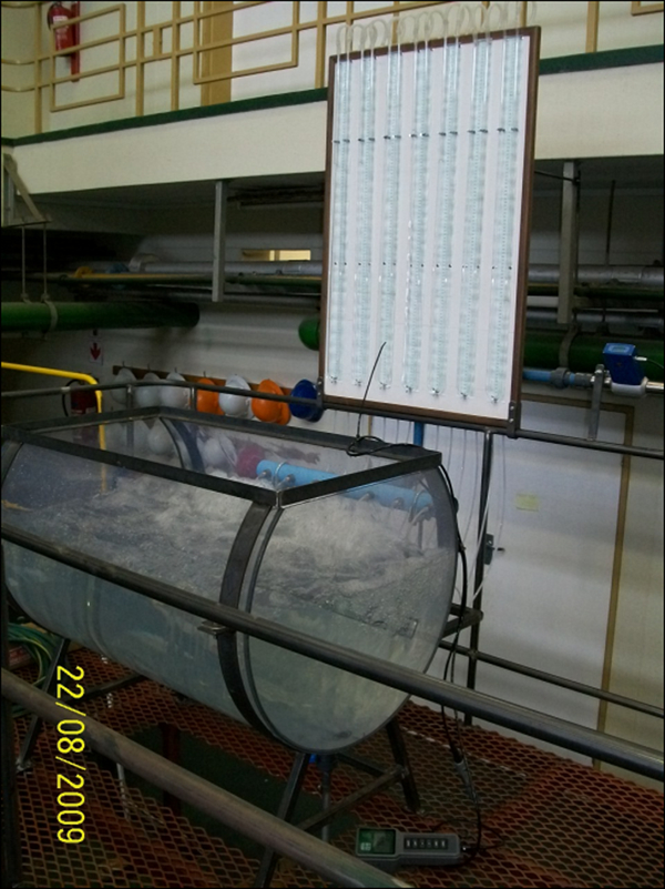
Physical 1∶5 scale water bath model of Peirce–Smith converter (PSC)
Physical simulation and model description
Similarity using dimensionless numbers is the key feature in the development of physical models. In the design process, geometrical, kinematic and dynamic similarities were observed through consideration of dimensionless numbers. Geometric similarity was achieved using scale factor, λ on all physical dimensions and dynamic similarity achieved through modified Froude number NFr*, which accounts for density difference of melts and injection gas as well as velocity of purged gas. Scale factor and modified Froude number are given in equations (1) and (2) respectively

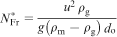

Schematic side view of model showing fluid levels and sampling depths
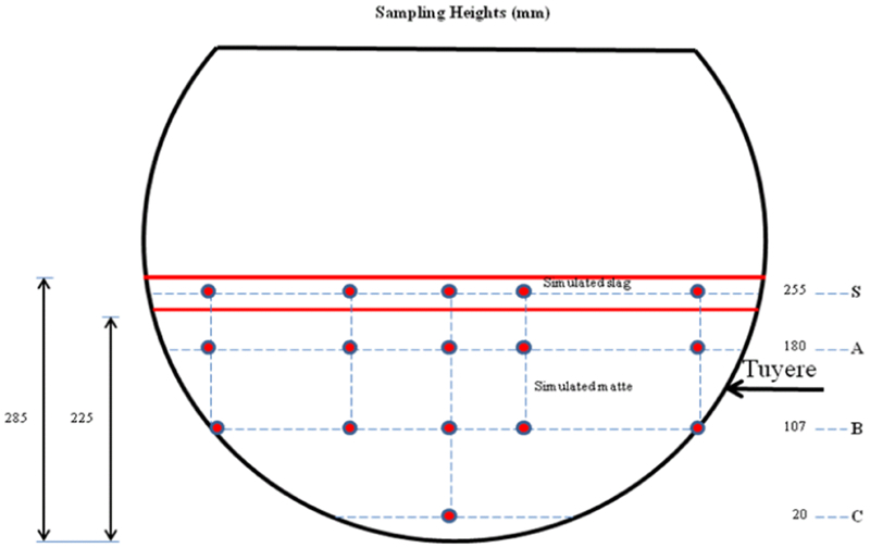
a side view of model showing grid and suspended syringes assembly for dispersion measurements and b emulsion settling in dispersion experiments
Fluid physical properties, dimensions and blowing conditions of a generic industrial PSC and the model
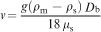
The only changing variable in the experiments was air volumetric flowrate, which was varied from 0·0085 to 0·0142 Nm3 s−1 with five levels presenting 75, 90, 100, 110 and 125% of typical equivalency model volumetric flowrate of 0·0113 Nm3 s−1. As shown in Fig. 3a, a grid was fitted on top of the cradle structure with 25 holes, uniformly distributed on the grid width and length were threaded rod fitted with veterinary surgical syringes at one end were attached giving a scattered 25 samples of emulsion per run. After air volumetric flowrate had stabilised, for a specific experimental set-up consideration, all syringes were pulled at once and contents were poured to pill holders. The emulsion in the pill holders was given sufficient time for complete phase separation (complete settling) as shown in Fig. 3b, where the volumes of water and kerosene were read directly.
There were four sampling depths in the experiments as shown in Fig. 2. In this right-up, there are referred to as planes of sampling (S-, A-, B- and C-Plane) with S-Plane positioned in the middle of the simulated slag layer thickness. S-Plane was used to measure dispersed phase hold-up (Dph) of simulated matte in simulated slag whereas A-, B- and C-Plane were used to measure Dph of simulated slag in simulated matte. The numbers appended to the planes in Fig. 2 are heights from the bottom of the model in millimetres were sampling was conducted.
Dispersed phase hold-up was calculated as the volumetric percentage (%) of kerosene (or water) to the total volume of emulsion drawn from the model after complete phase separation. On average, 20 mL of emulsion per sampling point were taken at every run. Dph was calculated by means of following equation
Numerical simulation and model description
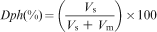
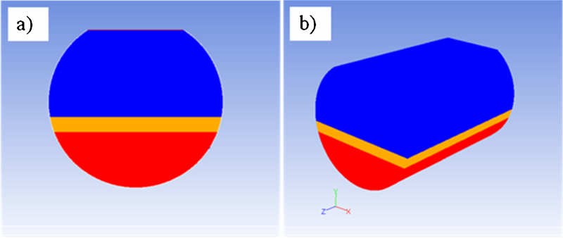
Experimental observation were numerically studied with CFD numerical code FLUENT version 12.1.4 on a 1·86 GHz Intel(R) Core(TM)2 processor with 2 GB RAM. Geometry and Mesh Building Intelligent Tool 2·4·6 was used for geometry creation of the 2D and 3D domain as given in Fig. 4. The 2D and 3D domain computational grids were made up of 26492 Map/Pave quad and 313529 hexahedral elements respectively for the entire flow domain with Equisize skew quality distribution as given in Fig. 5. This figure shows 99·97 and 98·86% elements with less than 0·4 Equisize skew respectively, which translate to good mesh quality (ANSYS, 2008), necessary for accurate and converged solution. A cooper tool method of meshing was used for the 3D domain.
Computational geometry a 2D and b 3D domain as exported in FLUENT
Computational domain mesh quality
Governing equations
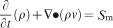
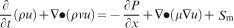
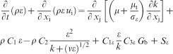
Physical phenomena in closed systems for incompressible fluids are described fully by continuity (mass) and momentum conservation equations. These are incorporated in the VOF formulation describing the fluid dynamics. The mass conservation or continuity and momentum equations are as given in equations (5) and (6) respectively.
Conservation mass or continuity equation
The VOF model
The VOF model was chosen to account for the multiphase flow. Phase surface behaviour of water, kerosene and air was captured by this model using the Geo-Reconstruction scheme. This is accomplished through surface tracking of the phase interfaces by the solution of a VOF continuity equation (equation (7)) for the volume fraction (VF) of at least one of the phases in the system. In the model, the different phases are treated numerically as interpenetrating continua thus inevitably introducing the concept of phasic VF were summation of VF in each computational cell sums to unity. In other words, if the ith fluid's VF in the cell is denoted by αi, then it follows that:
αi = 0: the computational cell is empty of the αi fluid
αi = 1: the computational cell is full of the αi fluid
0<αi<1: the computational cell contains at least one phase of αi deficit.
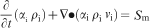
For the ith fluid phase, VOF equation has the following form:

The k–ϵ turbulent model
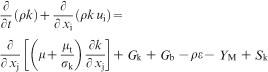
In order to incorporate the effects of turbulence on the flow field inside the model, Realisable k–ϵ model was implemented. This is a two equation model based on transport equations for the turbulence kinetic energy k and its rate of dissipation ϵ. It is a relatively recent development by (Shih et al., 1995) which offers improvements in the overall energy transfer. The transport equation for k is derived from exact equation, while the transport equation for ϵ is obtained from physical reasoning. Turbulence variables k and ϵ are obtained from transport equations (9) and (10) respectively


Phase physical properties
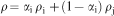
The properties appearing in the transport (equation (6)) are determined by the existence of the component phase in each computational cell. In a two phase system with phase VF, α with subscripts i and j, summation of phase fraction in the computational cell subject to constraint imposed by equation (8) yields

Method of solution
The VOF and k–ϵ turbulence model equations (5)–(15) were solved with CFD numerical code FLUENT version 12.1.4. This package is a finite volume solver using body fitted computational grids. Semiempirical method for pressure linked equations algorithm was used for pressure–velocity coupling with geo-reconstruction scheme for obtaining face fluxes, when the computational cell is near the interface using piecewise-linear approach (ANSYS, 2008). A time step of 0·001 s was used and found to be sufficient for maintenance of numerical convergence at every time step and stability. Convergence of numerical solution was determined based on surface monitoring of integrated quantities of bulk flow velocity and turbulence and scaled residuals of continuity, x-, y-, z-velocities, k and ϵ. The residuals of all quantities were set to 10−3 and the solution was considered converged when all the residuals were less than or equal to the set value.
Results and Discussion
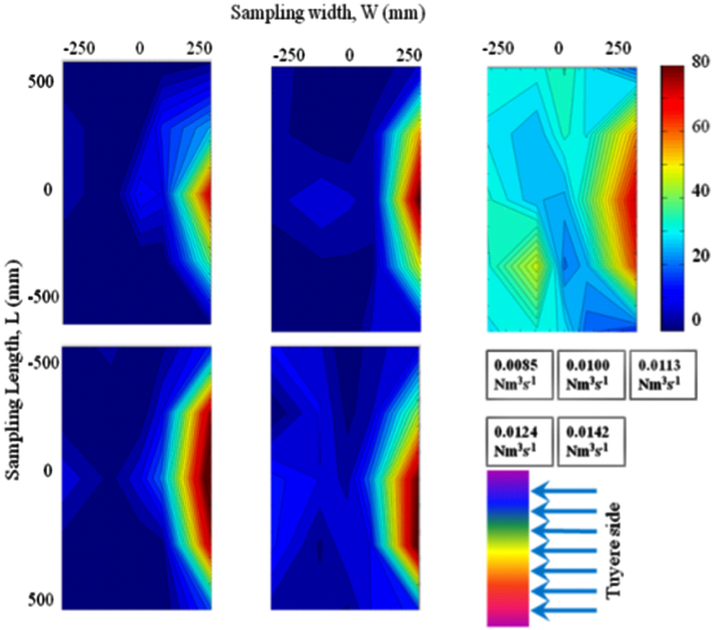
The numerical formulation described in the presiding section was used to verify the accuracy and integrity of the physical modelling results. In the numerical simulation, one air volumetric flowrate (0·0113 Nm3 s−1) was used in the transient 3D simulation. This verification was done by comparing the contours of measured Dph on four planes (S-, A-, B- and C-Plane) of the water bath with contours of VF of simulated matte in simulated slag at the same plane depth at different volumetric flowrates. Figure 6 shows an example of such comparison at a volumetric flowrate of 0·0113 Nm3 s−1 on S-Plane (simulated matte dispersed in simulated slag). MATrix LABoratory 7·5·0 statistical analysis code software was used for generation of contours of the measured Dph.
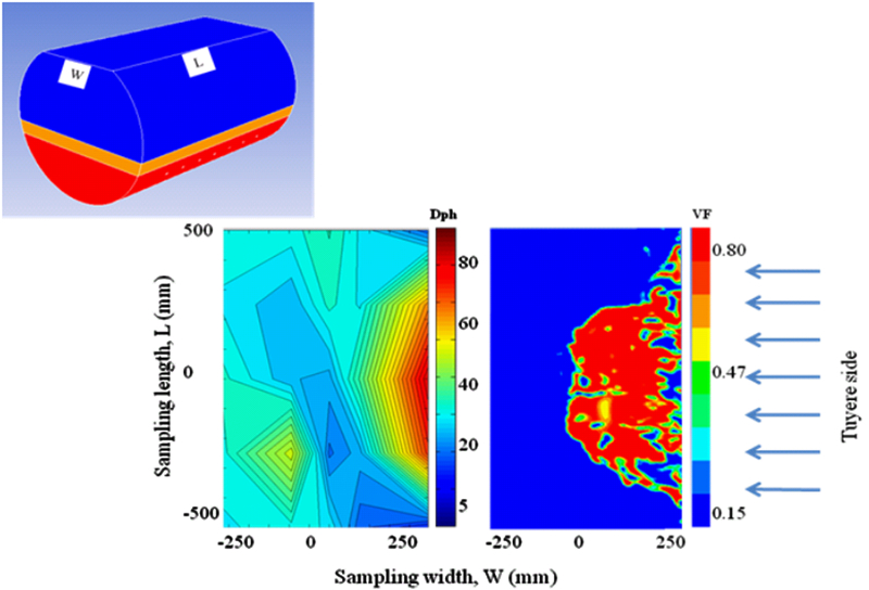
Contours of measured Dph in the S-Plane a compared with numerical b VF contours of simulated matte in simulated slag (flowrate 0·0113 Nm3 s−1)
In this work, it has been observed that the amount of dispersed simulated matte in simulated slag phase in the model increases with increasing air volumetric flow rate. Figure 7 shows the variation of average Dph in S-plane (simulated matte in simulated slag) as well as A-, B- and C-Plane (simulated slag in simulated matte) on the same axis. As air volumetric increases, it has been observed that the amount of average dispersed simulated slag in matte decreases. This situation could be attributable to the effects of increased splashing in the converter as air volumetric flowrate increases. Since no chemical reaction has been modelled in this work, the dispersion in the converter is due to mechanical entrapment only.
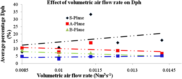
Variation of average Dph on plane S-, A-, B- and C-Plane with respect to air volumetric flowrate
According to (Koohi et al., 2008), the splashes in the PSC are mainly matte constituents as slag is pushed to the radial position, opposite the tuyere injection, forming a plume of matte. Splashes with enough kinetic energy will be dispersed out of the converter and those with insufficient kinetic energy will fall back into the reactor as observed from the time-scale, 2D transient simulation shown in Fig. 8 (t = 0·92 s).
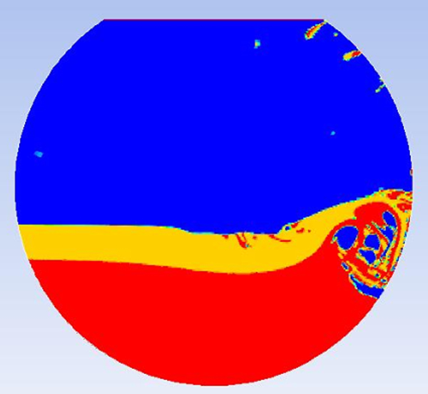
Calculated 2D transient flow pattern in bath showing matte splashing at time t = 0·92 s
As the splashes drops on the slag surface, the gravitational settling of the droplets will depend on the density and viscosity difference between the phases. The settling rate v of the matte phase assuming that the average droplet shape is spherical observes Stokes’ law which is mathematically expressed as

Calculated 2D transient flow pattern in bath with simulated slag and simulated matte from a 0·05 s, b 0·35 s, c 0·64 s, d 0·92 s, e 1·22 s and f 1·50 s after compressed air purging
The results of simulated matte dispersed in simulated slag in S-Plane for all air volumetric air flowrates considered in this work is presented in Fig. 10. It shows an increase in Dph with increased air volumetric flowrates.
Dph contours of simulated matte in simulated slag on the sampling plane S at different air volumetric flowrates
The effect of air volumetric flowrate on the dispersion of simulated slag in simulated matte has been observed to be different as shown in Fig. 7. As air volumetric flowrate increases, Dph decreases on all planes of sampling with the minimum dispersion occurring on the C-Plane, 20 mm from the bottom of the converter model. This is attributable to the fast precipitation of simulated slag emulsion droplets in simulated matte phase, the presumption being facilitated by high bath circulation velocity set up in the converter with increase in air volumetric flowrate. Figure 11 shows a comparison of the physical and numerical calculated Dph on A-Plane at 0·0113 m3 s−1.
Contours of the measured Dph on the A-Plane (simulated slag dispersed in simulated matte) a compared with numerical b VF contours of simulated slag dispersed in simulated matte (flowrate 0·0113 Nm3 s−1)
In the comparative deduction, it can be seen that there is insignificant dispersion of slag in matte in all sections of sampling considered in this study. However, there is minimal (insignificant) dispersion experienced in the central locations of the simulated matte phase presumably caused by a dead zone created at the centre of the converter in the bath recirculation loop which technically will not support precipitation of the dispersed phase due to low bath velocity and turbulence in that region. Work by Vaarno et al. (1998) established such a velocity vector flow field in the PSC.
Metallurgical Implications of results
From this study, a high retention of matte in the slag is evidently due to a combination of splashes from surface deformation in the plume region which drops to the slag surface and attachment of matte constituents into the slag as the gas crosses the slag-matte as dispersion droplets. The later phenomena has been studied and found to be dependent on the surface and interfacial surface tensions of the matte-slag system, governed by the flotation coefficient given by
As PSC is a batch process, a proper adjustment of the slag chemistry is necessary in order to maintain good settling conditions for the matte, according to equation (16). It may be compromised by the increase in viscosity if the slag assay is allowed to move to magnetite or silica saturated compositions, due to insufficient or excessive additions of silica sand. The problem is more sensitive to the fluxing practices at copper blow stage of copper making than in slag blow stages of nickel and copper converting (Taskinen et al., 2005). The recent findings from El Teniente converter and slag cleaning (Imris et al., 2005) have lead to the same conclusions. It is clear on the basis of the current results that the dispersion of slag in matte is not evident in PSC. Such entrapment of slag in matte is due to different processing environments and phase interactions in the tapping hole area (Liow et al., 2003).
Conclusion
In this study, we have experimentally and numerically studied fluid flow behaviour in industrial PSC using cold model simulations. The 2D and 3D simulations of the three phase system were carried out using VOF and realisable k–ϵ turbulence model to account for the multiphase and turbulence nature of the flow respectively. Dispersion of simulated matte in simulated slag has been found to increase with increase in air volumetric flowrate. Whereas the dispersion of simulated slag in simulated matte was observed to decrease with increase in air volumetric flowrate. The difference emanates from complex interaction of phases in terms of precipitation mechanisms, coagulation and floatation in the two scenarios as well as fluid motion set-up in the converter. Experimental results were in good agreement with numerical simulation results in the domain of experimental set-up.
Footnotes
Acknowledgements
The financial support received from NRF is greatly acknowledged. The authors also extends acknowledgement to the technical staff in the Process Engineering Laboratory for assistance with assembling model superstructure.